


7-Segment Display Control with Decoders 74LS47/48
This project involves designing and constructing a PCB that allows for the control of a 7-segment display using 74LS47 and 74LS48 decoders. The innovative feature of this design is its flexibility, allowing the use of both common-anode and common-cathode displays by simply configuring the DIS pin header. This makes the PCB adaptable to different types of displays without requiring physical changes to the circuit.
Main Components:
7-Segment Display: Used to show numbers and some characters. It can be common-anode or common-cathode.
74LS47/74LS48 Decoders:
74LS47: BCD to 7-segment decoder for common-anode displays.
74LS48: BCD to 7-segment decoder for common-cathode displays.
Pin Headers (DIS): Allow for configuring the PCB to work with the type of display connected.
Sockets: Facilitate the insertion and removal of integrated circuits without the need for soldering.
Power Supply: Provides the necessary voltage for the circuit's operation.
Protection Resistors: Prevent overheating of the display segments.
Operation:
BCD Inputs: The PCB receives a BCD (Binary-Coded Decimal) value through inputs connected to the 74LS47 or 74LS48 decoder.
Decoding: The decoder converts the BCD input into the signals needed to activate the segments of the 7-segment display. Depending on whether the display is common-anode or common-cathode, the 74LS47 or 74LS48 decoder is used.
DIS Pin Header Configuration:
Common-Anode: If using a common-anode display, configure the DIS pin header to activate the 74LS47 decoder.
Common-Cathode: If using a common-cathode display, configure the DIS pin header to activate the 74LS48 decoder.
Segment Connections: The decoder's outputs are connected to the segments of the display. Each segment (a, b, c, d, e, f, g) is activated according to the received BCD value, displaying the corresponding number on the display.

7-Segment Display Control with Decoders 74LS47/48
*PCBWay community is a sharing platform. We are not responsible for any design issues and parameter issues (board thickness, surface finish, etc.) you choose.


Raspberry Pi 5 7 Inch Touch Screen IPS 1024x600 HD LCD HDMI-compatible Display for RPI 4B 3B+ OPI 5 AIDA64 PC Secondary Screen(Without Speaker)
BUY NOW


- Comments(0)
- Likes(1)
More by Pablo Mirrortrec
-
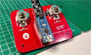 Radio control with nrf24
A control for radio frequency projects with the NRF24 module, where we have two joysticks to control...
Radio control with nrf24
A control for radio frequency projects with the NRF24 module, where we have two joysticks to control...
-
 Arduino NRF24 flight computer
In this project, the goal is to control servo motors using data from an MPU (Motion Processing Unit)...
Arduino NRF24 flight computer
In this project, the goal is to control servo motors using data from an MPU (Motion Processing Unit)...
-
 555 for breadboard o 555 para protoboard
Tired of always having to build an astable 555 circuit for clock pulse projects? This PCB helps you ...
555 for breadboard o 555 para protoboard
Tired of always having to build an astable 555 circuit for clock pulse projects? This PCB helps you ...
-
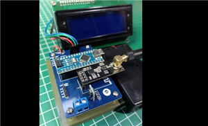 Control module by nrf24
This PCB is designed for wireless data transmission and reception using the nrf24 RF module. Its ver...
Control module by nrf24
This PCB is designed for wireless data transmission and reception using the nrf24 RF module. Its ver...
-
 USB-C power supply
Type C power supply for those who don't know how to solder SMD components or have difficulty obtaini...
USB-C power supply
Type C power supply for those who don't know how to solder SMD components or have difficulty obtaini...
-
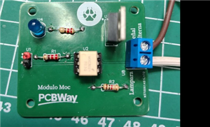 Modulo Moc y Triac
A mini module capable of controlling the passage of alternating current, adding to the 5v relay modu...
Modulo Moc y Triac
A mini module capable of controlling the passage of alternating current, adding to the 5v relay modu...
-
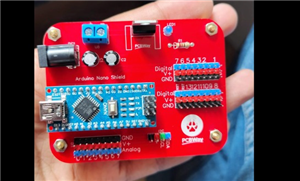 Shield Arduino Nano
Base for arduino Nano which has a stable 5v regulator to connect sensors or servo motors, with i2c c...
Shield Arduino Nano
Base for arduino Nano which has a stable 5v regulator to connect sensors or servo motors, with i2c c...
-
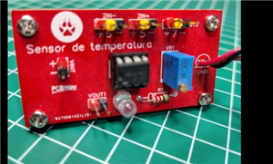 Temperature sensor com lm358 and lm3
Temperature sensor with lm358 and lm35 where we can drive things thanks to the output it has, analog...
Temperature sensor com lm358 and lm3
Temperature sensor with lm358 and lm35 where we can drive things thanks to the output it has, analog...
-
 5v power supply v2
Power supply for 5v constant thanks to the regulator that incorporates but this not only makes it fu...
5v power supply v2
Power supply for 5v constant thanks to the regulator that incorporates but this not only makes it fu...
-
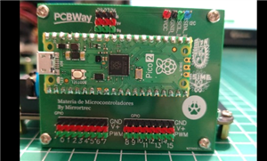 base for raspberry pi pico
A base for the raspberry pi pico to use the gpio ports in a simpler way as well as to be able to use...
base for raspberry pi pico
A base for the raspberry pi pico to use the gpio ports in a simpler way as well as to be able to use...
-
 7-segment display
PCB board designed for beginners in electronics, compatible with 7-segment displays both common anod...
7-segment display
PCB board designed for beginners in electronics, compatible with 7-segment displays both common anod...
-
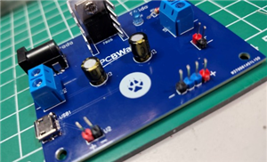
 5v power supply mirror
Simple 5v power supply but with multiple connectors for those occasions where we do not have the spe...
5v power supply mirror
Simple 5v power supply but with multiple connectors for those occasions where we do not have the spe...
-
 7-Segment Display Control with Decoders 74LS47/48
This project involves designing and constructing a PCB that allows for the control of a 7-segment di...
7-Segment Display Control with Decoders 74LS47/48
This project involves designing and constructing a PCB that allows for the control of a 7-segment di...
-
 LED Sequencer with CD4017
This project consists of a printed circuit board (PCB) designed to control a sequence of LEDs using ...
LED Sequencer with CD4017
This project consists of a printed circuit board (PCB) designed to control a sequence of LEDs using ...
-
 Darkness sensor
The circuit is designed to turn on an LED when the ambient light decreases, i.e. when it is dark. Th...
Darkness sensor
The circuit is designed to turn on an LED when the ambient light decreases, i.e. when it is dark. Th...
-
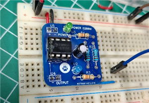
 The 3 modes of the 555
The reason for this project is that students around the world can see how the 555 can have different...
The 3 modes of the 555
The reason for this project is that students around the world can see how the 555 can have different...
-
Programmable Mist Maker - XIAO / QT PY Extension
172 0 0 -
RadioHAT - Raspberry Pi radio development platform
182 0 1 -
-
-
-
-
ARPS-2 – Arduino-Compatible Robot Project Shield for Arduino UNO
2768 0 5 -
A Compact Charging Breakout Board For Waveshare ESP32-C3
3276 3 8 -
AI-driven LoRa & LLM-enabled Kiosk & Food Delivery System
3530 2 2


