


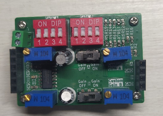


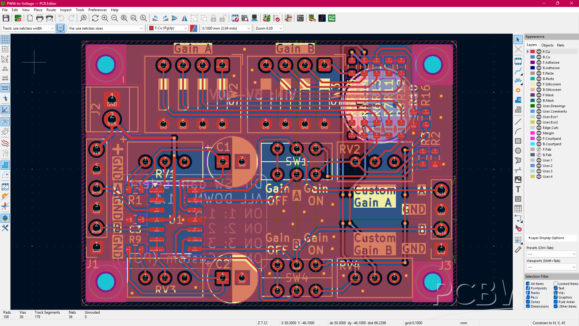
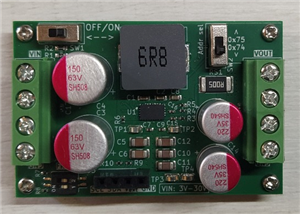
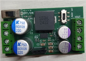
2 Channel PWM to Analog converter
This is a PWM to analog voltage converter. Given an input PWM the output will be proportional to the duty cycle of the PWM signal.
It can work with any MCU, arduino, esp32, stm32 etc.. As long as the supply at the circuit is 3V-40V (tested up to 35V). For example a 1.8V (or less) pwm signal can be used as an input but you should power the circuit with at least 3V
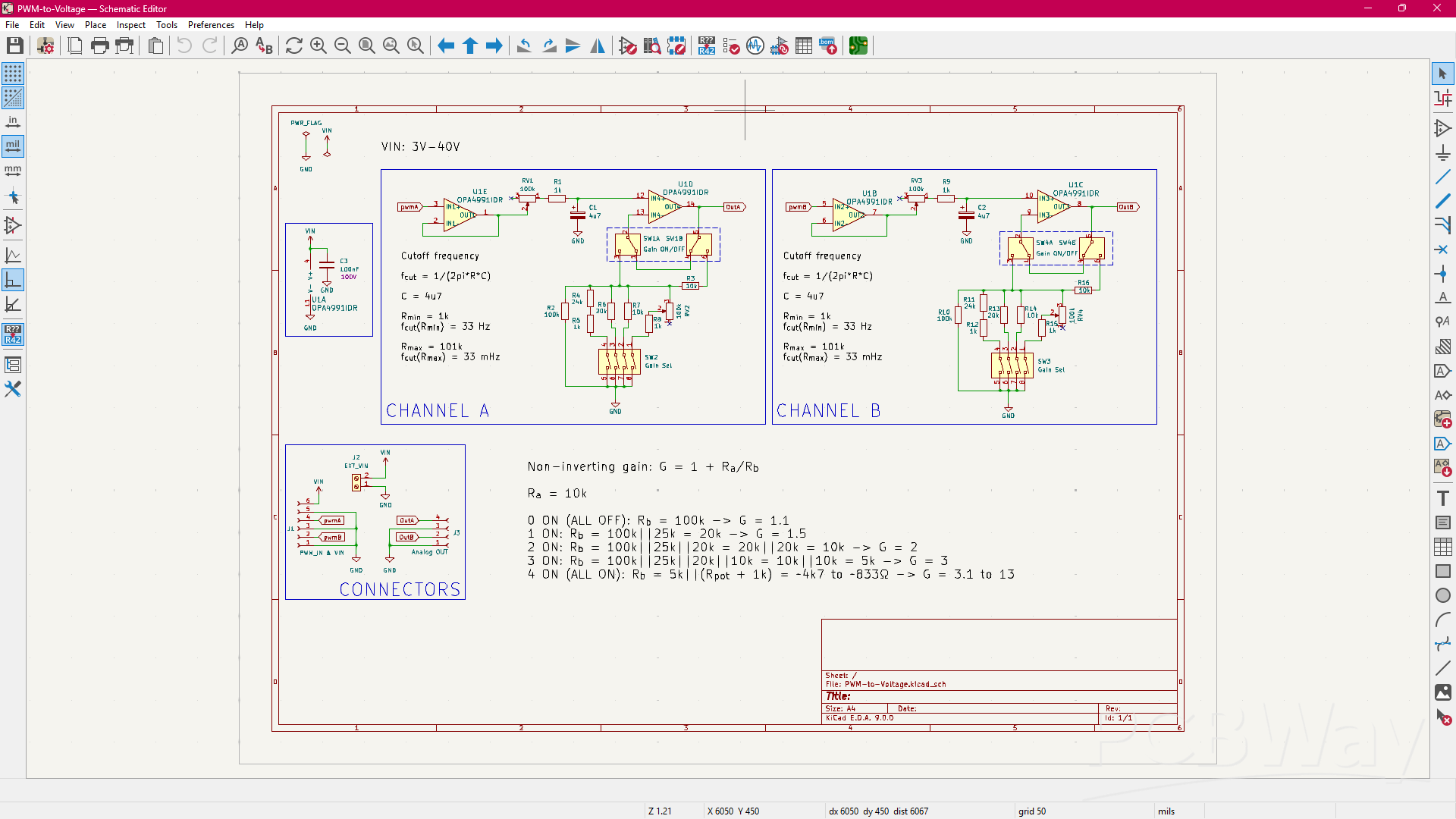
There is an adjustable RC filter whose cutoff frequency can be adjusted from 33mHz to 33Hz
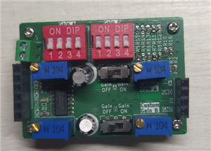
The circuit offers also the possibility to apply gain at the output. You can control the gain with the DIP switches:
ALL DOWN: G = 1.1
ON 1: G = 1.5
ON 2: G = 2
ON 3: G = 3
ON 4: Gain is adjustable using the potentiometer (gain up to 13)
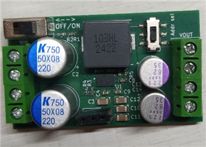
Dimension (Assembled, LxWxH) : 48.7x34.4x19 mm
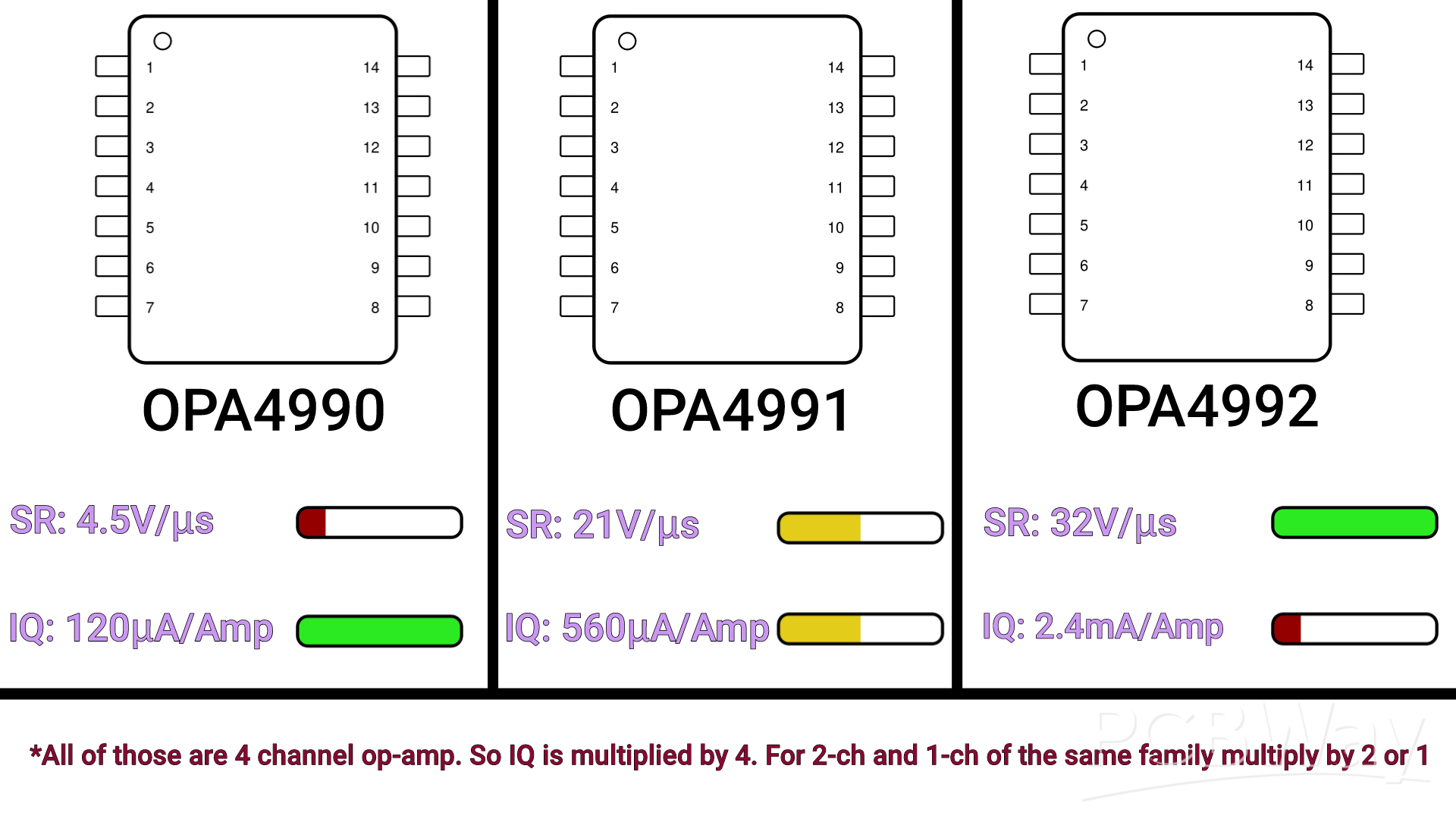
You can change the OPA4991 with the OPA4992 or OPA4990, they are pin-to-pin compatible. Below there's a brief comparison between them
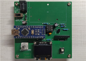
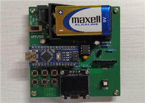
ALL the waveforms you see here are produced by an ARDUINO NANO and my PWM to analog converter (with OPA4992)
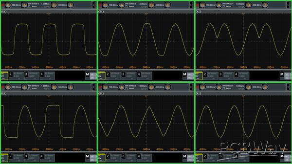
Top-left: Smoothed square, Top-mid: Sine-Trapezoidal, Top-right: Mirrored sine
Bottom-left: "Squareish"-sine, Bottom-mid: Sine-Triangular, Bottom-right: Sine
There's also the possibility to apply gain:
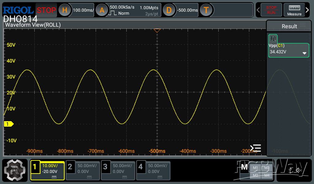
34Vpp(0 to 34V) sine wave
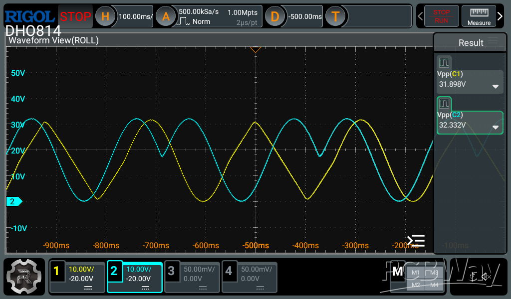
Channel 1: Sine-Triangular 32Vpp
Channel 2: Mirrored sine 32Vpp
Here I've used two arduino pwm pins
NOTE: You're limited in frequency by your RC filters values, the more you approach the cutoff frequency the more the signal is attenuated
2 Channel PWM to Analog converter
*PCBWay community is a sharing platform. We are not responsible for any design issues and parameter issues (board thickness, surface finish, etc.) you choose.


Raspberry Pi 5 7 Inch Touch Screen IPS 1024x600 HD LCD HDMI-compatible Display for RPI 4B 3B+ OPI 5 AIDA64 PC Secondary Screen(Without Speaker)
BUY NOW


- Comments(0)
- Likes(0)
More by BurningElectronics YT
-
 I2C controllable buck-boost converter (2Layer version)
NEW VERSION HERE: https://www.pcbway.com/project/shareproject/NEW_I2C_controllable_buck_boost_conver...
I2C controllable buck-boost converter (2Layer version)
NEW VERSION HERE: https://www.pcbway.com/project/shareproject/NEW_I2C_controllable_buck_boost_conver...
-
 LED TESTER (with CODED SWITCH)
Just a simple LED Tester that can test your LEDs from 0.1mA to (almost) 50mA. Just insert your LED a...
LED TESTER (with CODED SWITCH)
Just a simple LED Tester that can test your LEDs from 0.1mA to (almost) 50mA. Just insert your LED a...
-
 LED TESTER (with PUSHBUTTONS)
Just a simple LED Tester that can test your LEDs from 0.1mA to (almost) 50mA. Just insert your LED a...
LED TESTER (with PUSHBUTTONS)
Just a simple LED Tester that can test your LEDs from 0.1mA to (almost) 50mA. Just insert your LED a...
-
 NEW! I2C controllable buck-boost converter V3.0
This is my new, upgraded, I2C controllable buck-boost converter based on the TPS55289. You can contr...
NEW! I2C controllable buck-boost converter V3.0
This is my new, upgraded, I2C controllable buck-boost converter based on the TPS55289. You can contr...
-
 2 Channel PWM to Analog converter
This is a PWM to analog voltage converter. Given an input PWM the output will be proportional to the...
2 Channel PWM to Analog converter
This is a PWM to analog voltage converter. Given an input PWM the output will be proportional to the...
-
 I2C controllable buck-boost converter
NEW VERSION HERE: https://www.pcbway.com/project/shareproject/NEW_I2C_controllable_buck_boost_conver...
I2C controllable buck-boost converter
NEW VERSION HERE: https://www.pcbway.com/project/shareproject/NEW_I2C_controllable_buck_boost_conver...
-
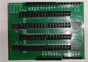 8x TCA9555 SHIELD (+128 pins for Arduino)
This pcb it's made for people who need tons of pins. In fact this shield adds 128 pins to your Ardui...
8x TCA9555 SHIELD (+128 pins for Arduino)
This pcb it's made for people who need tons of pins. In fact this shield adds 128 pins to your Ardui...
-
-
-
-
ARPS-2 – Arduino-Compatible Robot Project Shield for Arduino UNO
2677 0 5 -
A Compact Charging Breakout Board For Waveshare ESP32-C3
3157 3 8 -
AI-driven LoRa & LLM-enabled Kiosk & Food Delivery System
3423 2 2 -
-
-


