1. Blog>
  2. PCIe PCB Layout Guidelines: Key Design Rules for High-Speed Routing

PCIe PCB Layout Guidelines: Key Design Rules for High-Speed Routing

by: Mar 31,2026 295 Views 0 Comments Posted in PCB Design & Layout

pcie pcb layout pci routing guidelines pcie layout guidelines pcie pcb layout guidelines pcie routing guidelines

What is PCI Express (PCIe)

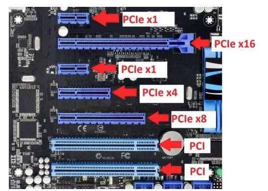
PCI Express (PCIe) is a high-speed serial computer expansion bus standard. It adopts a point-to-point, dual-channel architecture that provides dedicated bandwidth for each connected device, eliminating shared bus limitations. One of its primary advantages is its high data transfer rate.


Key PCIe PCB Layout Principles

Component Placement Optimization

  • Distance Between Gold Fingers and Chip: The trace length from the gold finger edge to the PCIe chip pins should be ≤ 4 inches (100 mm) to minimize transmission loss.
  • AC Coupling Capacitor Placement: 100 nF capacitors (typically in the 75–200 nF range) should be placed symmetrically and close to the gold fingers. 0402 packages are preferred, while through-hole components are not recommended.
  • Sensitive Circuit Isolation: Clock and reset circuits should be kept away from differential pairs. Avoid routing high-speed signals under the PCIe chip; a solid GND plane is recommended beneath the device.

Stackup and Reference Planes

  • 4-Layer or More PCB Design: Use a symmetric stackup such as Signal–GND–PWR–Signal. Differential pairs should preferably be routed as stripline (between two reference planes) to reduce EMI.
  • Reference Plane Continuity: Avoid routing differential pairs across split planes. When changing layers, place 1–3 ground vias near signal vias (spacing ≤ 300 mil) to maintain a continuous return path.


Core PCIe Routing Guidelines

Impedance Control and Spacing

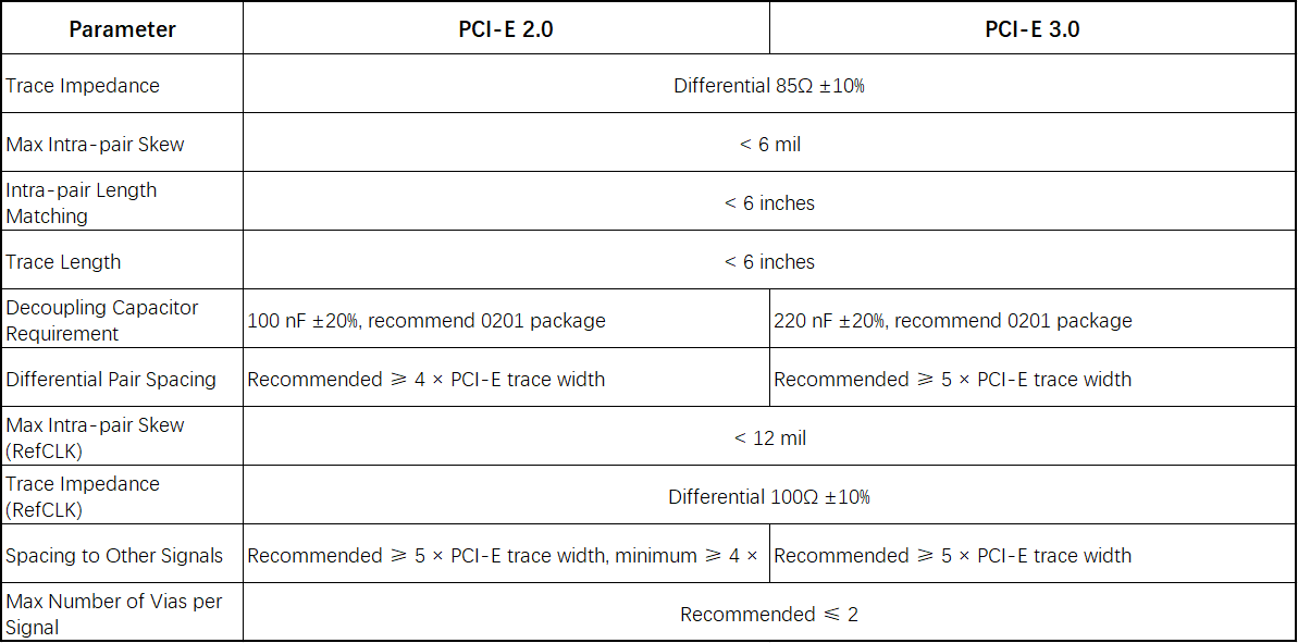
Differential Impedance:

  • 100Ω ±10% (PCIe 1.0/2.0) or 85Ω (PCIe 3.0 and above), controlled by adjusting trace width and spacing (e.g., microstrip: 5 mil width / 7 mil spacing).

Spacing Rules:

  • Maintain constant spacing within differential pairs to ensure impedance continuity
  • Spacing between different pairs and non-PCIe signals ≥ 20 mil (or ≥ 4× dielectric thickness)
  • Increase to ≥ 30 mil for high-voltage or high-frequency signals


Length Matching and Timing

Within Differential Pair

  • Length mismatch ≤ 5 mil, with matching performed close to the source pins.

Between TX and RX Pairs

  • Exact length matching is not required (due to embedded clocking), but it is recommended to keep length difference < 2 cm.

Serpentine Routing Rules

  • Bend length ≥ 3× trace width (e.g., 15 mil for 5 mil trace)
  • Spacing between serpentine segments < 2× normal pair spacing


Via and Bending Control

Via Usage

  • TX differential pairs: ≤ 4 vias
  • RX differential pairs: ≤ 2 vias
  • Via pad ≤ 25 mil, drill ≤ 14 mil
  • Use symmetric placement and back-drilling to remove stubs

Bending Angles

  • Avoid 90° bends. Use angles ≥ 135°, with bend length ≥ 1.5× trace width (e.g., 7.5 mil for 5 mil trace).


Ground Shielding and Isolation

Ground Guarding

  • Add ground traces on both sides of differential pairs, with stitching vias (spacing < 300 mil) to reduce crosstalk.

Gold Finger Area

  • Remove all copper planes beneath the gold fingers. Connect chassis ground through a high-voltage capacitor (e.g., 2 kV, 1000 pF) using a single-point connection.


PCIe Generational Differences and Design Considerations

Key Differences Between PCIe 2.0 and PCIe 3.0

Data Rate

  • PCIe 2.0 supports up to 5 GT/s, while PCIe 3.0 increases the data rate to 8 GT/s, significantly improving bandwidth. PCIe 3.0 remains backward compatible with PCIe 1.x/2.x (2.5 GT/s and 5 GT/s).

Encoding Scheme

  • PCIe 3.0 eliminates traditional 8b/10b encoding and introduces enhanced signaling, improved data integrity, equalization techniques, PLL improvements, clock data recovery, and other advanced technologies.


Differences in PCIe PCB Layout Requirements (PCIe 2.0 vs PCIe 3.0)

Join us
Wanna be a dedicated PCBWay writer? We definately look forward to having you with us.
  • Comments(0)
Upload photo
You can only upload 5 files in total. Each file cannot exceed 2MB. Supports JPG, JPEG, GIF, PNG, BMP
0 / 10000
    Back to top