


|
KiCADKicad
|
|

|
STM32CubeIDESTMicroelectronics
|
|

|
Visual StudioMicrosoft
|
Wireless Battery-less Temperature Sensor
Wireless Battery-less Temperature Sensor project features a temperature sensor powered by a very small solar panel that does not utilize any battery, but still allows the device to run continuously both day and night. Running at night is achieved by very advanced optimization of device power consumption and the required energy used at night is stored in a supercapacitor which is charged by the sun during the day. The device uses a very accurate digital temperature sensor with a resolution of 0.005°C and an accuracy of 0.25°C but for best results any other external sensor can be connected using internal pin header. Core parts are in a small waterproof box with a transparent cover. The device integrates a wireless transmitter and every 15 minutes sends an encrypted packet containing details about temperature from a recent 15-minute timespan. As part of the project, I also created a gateway based on a microcontroller controlling the wireless receiver for receiving data from nearby sensors and Raspberry Pi for saving data for further visualization.
Sample Sponsors
At the beginning I would like to say thank you to companies which helped me to realize this project by sending me a free samples of some parts which I used in this project:

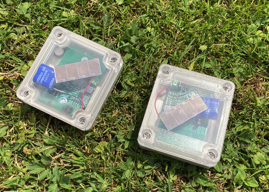
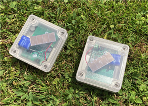
Sensor device
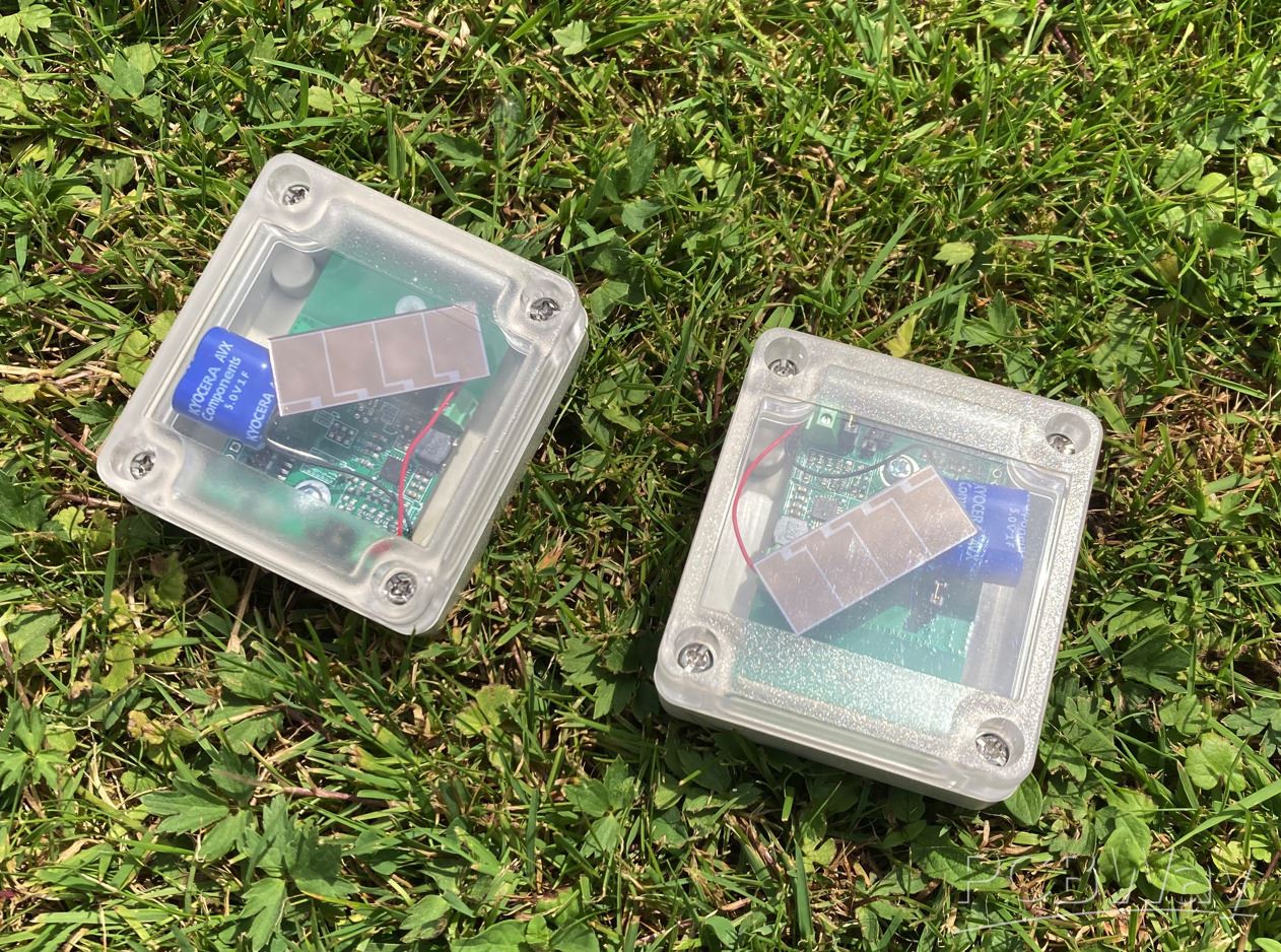
Sensor device is designed as ultra-low power device. I designed whole device from scratch. As part of project, I designed the printed circuit board and programmed firmware for the microcontroller which I used on board. High level view of the device is shown on following block diagram:
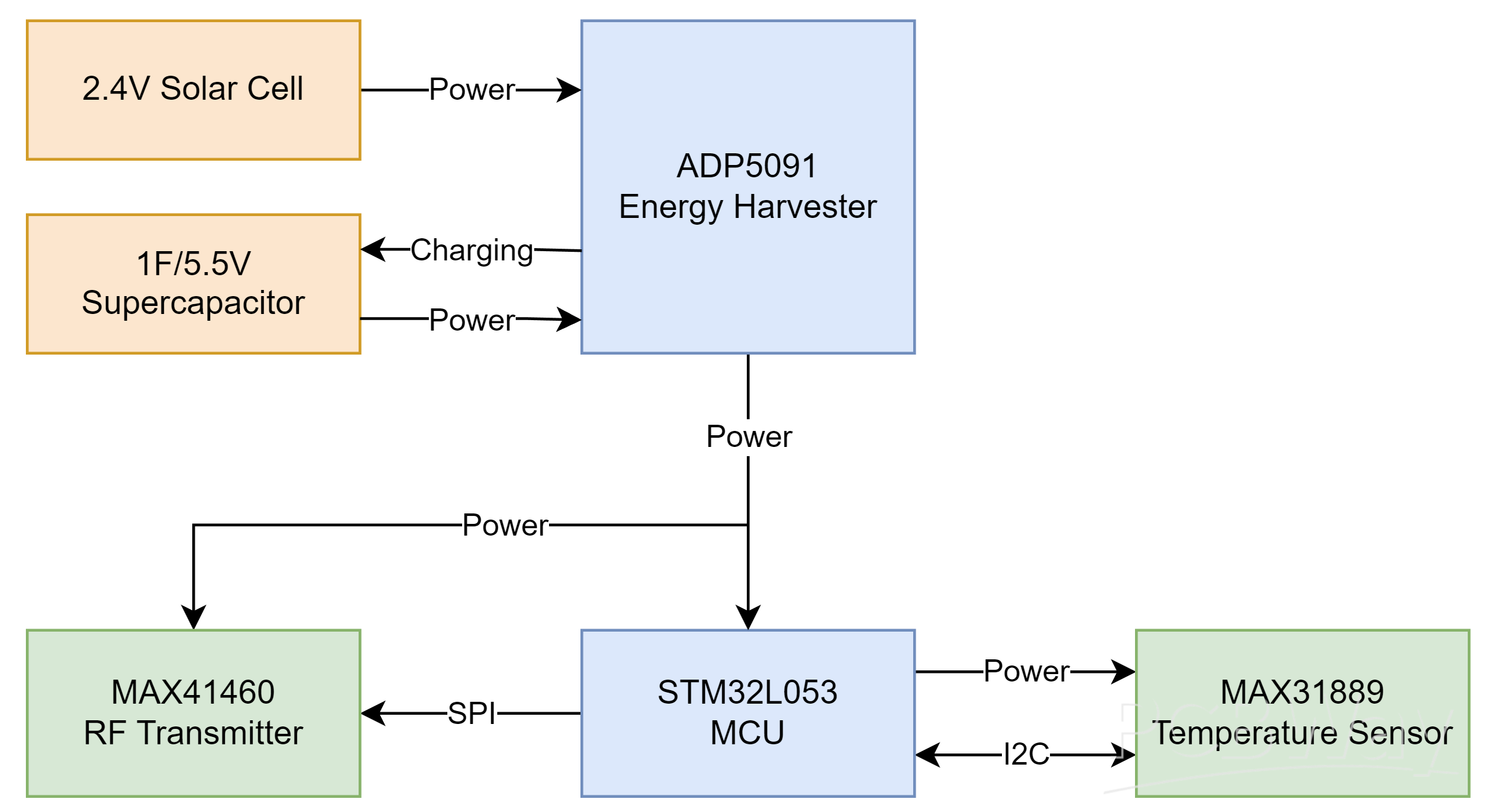
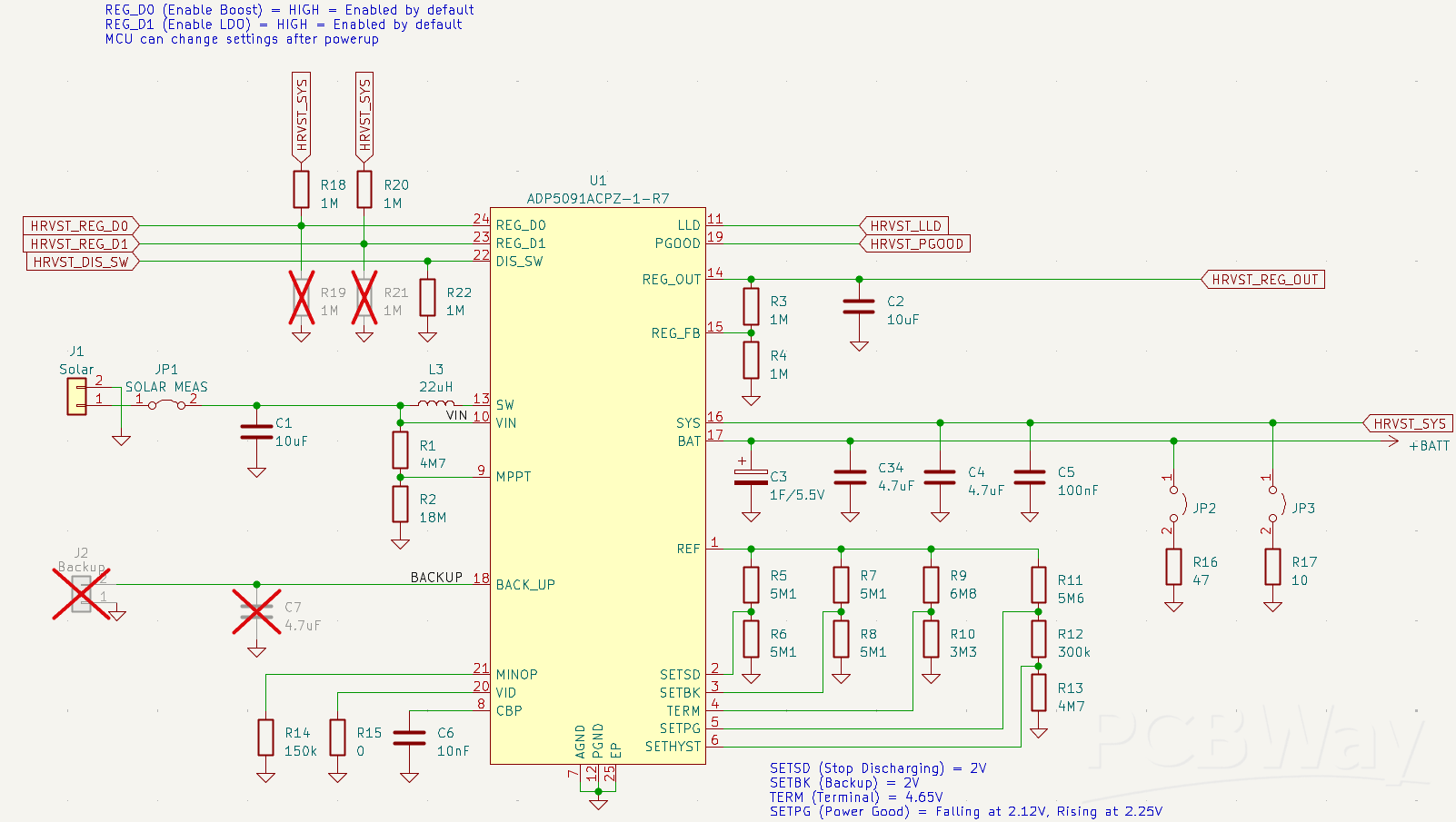
Solar Energy harvesting
The most important chip in this project is not microcontroller, but energy harvester chip. I chose ADP5091 which seems like one of the most advanced in this category on market. In opposition, it requires many external components for configuring various parts of it. It took me long time to find it and even more time to develop device with it. It is device which converts voltage from the solar panel to the higher voltage and charges storage element (supercapacitor) by such voltage. It implements MPPT (Maximum Power Point Tracking) for harvesting as much solar power as possible. At the end it generates regulated 2V for the low power microcontroller. This chip “boot” even before microcontroller. Microcontroller boot as soon as the supercapacitor get charged to acceptable level. Because very small solar panel is used, it took several hours to boot for first time. Then it maintain voltage in range suitable for more than 24 hours of operation having large enough budgets for non-sunny winter days. The connection of this chip look as follows. You can download detailed schematics in PDF from attachments of this article.
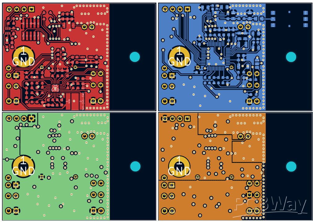
PCB
I designed PCB as 4 layered. Dimensions, hole location and component placement is adjusted to match selected case. Top layer is red, inner layer near top is green, bottom layer is blue, inner layer near bottom is orange.
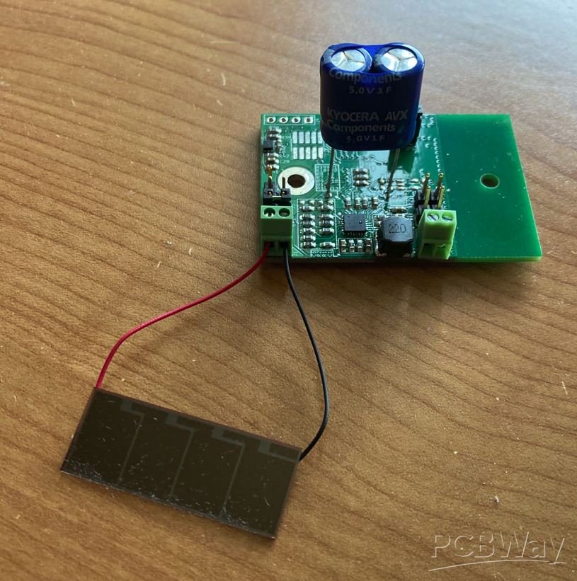
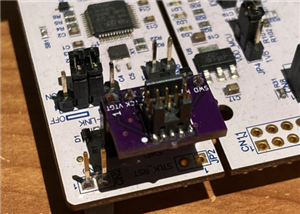
At development time, it looked on my desk as follows:
Solar Power Harvesting Configuration
When developing, I faced lot of issue and had to reconfigure lot of parameters (configuration resistor values). Parameters are tuned for specific parts which are mentioned in BOM. If you pick different parts (especially supercapacitor), you will likely need to modify resistor values accordingly. In those cases, follow guidance in ADP5091 datasheet.
One interesting issue which caused me to modify some thresholds was that I set startup voltage very near chip minimum threshold and did not consider startup discharge caused by decoupling capacitor after regulator turns up. It caused device to cycle. After it charged supercap enough to start, it started, but charging decoupling caps on regulated side almost immediately discharged main supercap under critical voltage needed for operation, and harvester decided to stop regulator. I had to increase that gap by changing resistor values in configuration resistor dividers.
Similarly, when I was evaluating multiple other types of supercapacitors, I noticed that some supercapacitors have very high ESR and need additional (non-super) capacitor in parallel to make it working.
Firmware
Very important part of the project is STM32 firmware. Firmware uses advanced techniques for reducing power consumption of the device. Firmware uses Real Time Clock peripheral for periodical wake up of the microcontroller which happens every 30 seconds. After wake-up, firmware does a temperature measurement and measurement of the supercapacitor voltage. Measured data are added to the statistics which are wirelessly transmitted once per 15 minutes. After completing job, microcontroller shutdown most part of the system and go sleep for around 30 seconds until next run. In this almost 30-second-long period system consume very low current which allows device to run from the sun all day and also in night because of using supercapacitor.
Wireless Transmission and Data Format
Device use MAX41460 chip for radio transmissions. It works on 868.3 MHz frequency which can be slightly changed by modifying firmware. It uses most simple ASK and OOK modes. It is my first RF project, so I begin with this simple mode. Disadvantage is that performance is not very good and when receiver is in home after several walls it lost most of the packets. For real use I will later improve reliability by improving protocol by supporting retransmissions and possibly switching to more advanced GFSK modulation instead of ASK. All used chips are ready to support this and currently it is just about SW implementation.
As mentioned above, firmware once per 15 minutes sends AES-128 encrypted block of data. AES key is pre-shared and is written in firmware source code. After downloading sources, you should generate and update source with your own AES key. Amount of transferred data is equal to AES-128 block size: 16 bytes. Before sending data, device sends unique device ID which can be used for identifying decryption key. Unique ID is derived from unique ID provided by STM32 MCU. There is no plain-text checksum. Instead, there is CRC8 checksum inside encrypted data, so after decrypting, you can check it. If error happen, decryption completely fails and packet’s data as well as CRC8 will be corrupted. Remaining 15 bytes of data contains three 5-min slots and contains minimum, maximum and average temperatures. Finally, packets also contain 3 measurements of supercap voltages.
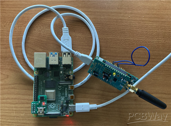
Gateway
For receiving data from the nearby sensors, I designed gateway. Gateway is built using MAX32655 microcontroller which is connected to the wireless receiver which listen for the data. I used devkits and did not design my own board for this because this device is intended to be placed indoor and form factor is not very important (at least for me). One gateway can handle data from thousands of nearby sensors. Microcontroller configures connected receiver and process received data. When it detects transmission of packet, it parses them and send them over serial line to the Raspberry Pi. Raspberry Pi saves data from all sensors to the CSV file. Before using collected data, they need to be decrypted. I made helper utility which can decrypts packets if file with encryption/decryption keys is provided. Later I visualize these data in Excel, but you can write simple scripts which will, for example, send data to cloud of your choice. But I prefer local data processing.
Wireless Battery-less Temperature Sensor
*PCBWay community is a sharing platform. We are not responsible for any design issues and parameter issues (board thickness, surface finish, etc.) you choose.


Raspberry Pi 5 7 Inch Touch Screen IPS 1024x600 HD LCD HDMI-compatible Display for RPI 4B 3B+ OPI 5 AIDA64 PC Secondary Screen(Without Speaker)
BUY NOW


- Comments(2)
- Likes(3)
 More by misaz
-
 Raspberry Pi Serial Console Mini Hat
This project contains Mini-HAT with USB-to-UART converter connected to pin header of Raspberry Pi an...
Raspberry Pi Serial Console Mini Hat
This project contains Mini-HAT with USB-to-UART converter connected to pin header of Raspberry Pi an...
-
 Onboard ST-Link to Standard ARM Cortex Debug Connector Adapter
It is adapter designed as adapter for 6-pin headers which are present on most STM32 Nucelo and Disco...
Onboard ST-Link to Standard ARM Cortex Debug Connector Adapter
It is adapter designed as adapter for 6-pin headers which are present on most STM32 Nucelo and Disco...
-
 Wireless Battery-less Temperature Sensor
 project features a temperature sensor powered by a very sma...
Wireless Battery-less Temperature Sensor
Wireless Battery-less Temperature Sensor project features a temperature sensor powered by a very sma...
-
 <100mm 5-port patch panel
It is a DIY non-rack mountable 5-port RJ45 ethernet passthrough patch-panel board where are ethernet...
<100mm 5-port patch panel
It is a DIY non-rack mountable 5-port RJ45 ethernet passthrough patch-panel board where are ethernet...
-
Programmable Mist Maker - XIAO / QT PY Extension
803 1 0 -
RadioHAT - Raspberry Pi radio development platform
647 0 1 -
-
-
-
-
ARPS-2 – Arduino-Compatible Robot Project Shield for Arduino UNO
3112 0 6 -
A Compact Charging Breakout Board For Waveshare ESP32-C3
3731 3 8 -
AI-driven LoRa & LLM-enabled Kiosk & Food Delivery System
4057 2 2


