


|
arduino IDEArduino
|
Motobot-with-Robotic-Arm-Schematic_PCB_Motobot-with-Robotic-Arm-Schematic_2024-10-14
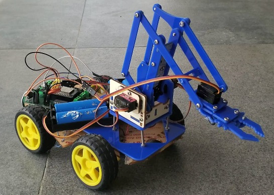
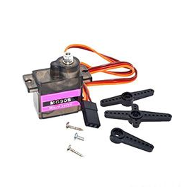
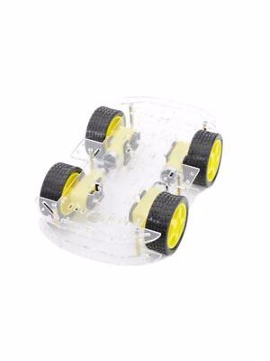
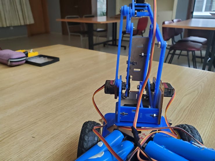
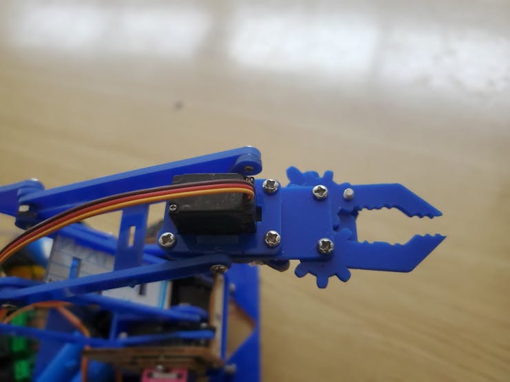
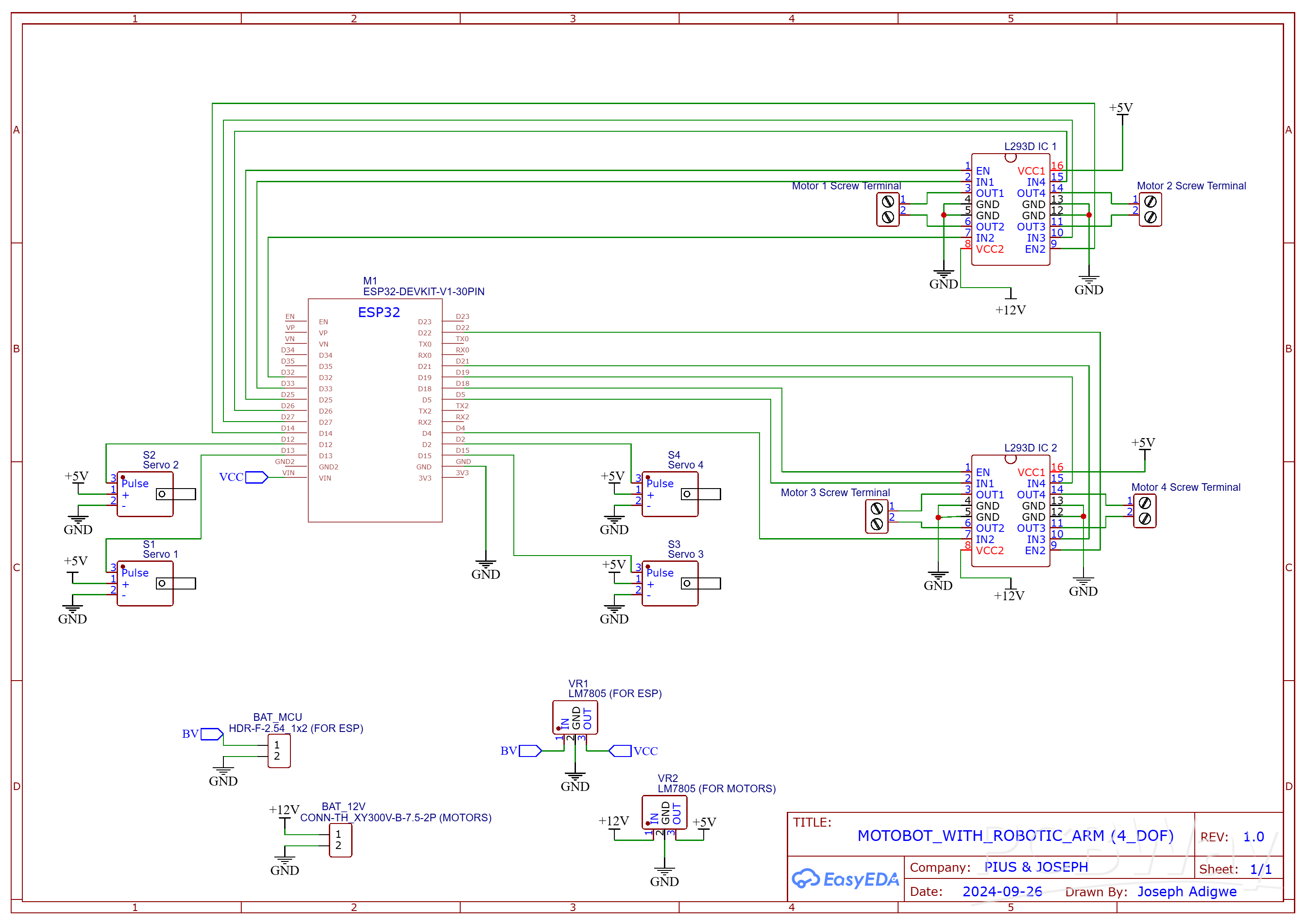
The RC car robotic arm is simply an RC car on wheels. The arm is a 4DOF robotic arm, meaning it has four moving parts.I used Mg90s servo motors since they are metallic, but the plastic Sg90s should work also. As seen in the schematic diagram below. I used two separate power supplies, each made up of 2S lithium ion (Li-on) batteries, one for the MCU and the other for the motors. This was to prevent interference of the voltage fluctuations and electrical noise generated by the motors from disrupting the MCU’s performance.
Why series batteries?
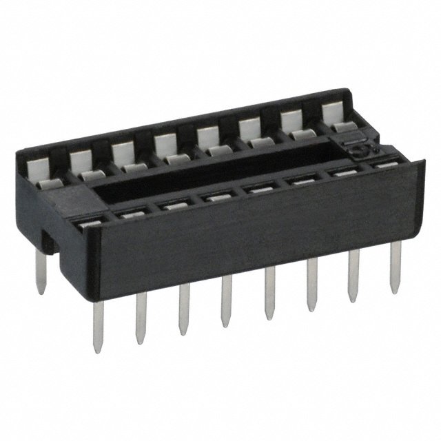
For the MCU, I connected two batteries in series because one Li-on battery produces approximately 4.2V at full charge, but the MCU needs 5V; as a result, I, connected two lipo batteries in series to get 8.4V and used the 7805 voltage regulator to step it down to 5V. Similarly, for the motors, the servos and the motor driver IC internal logic needed 5V, and I wanted to power the motors with more than 5V for more power. So, I employed the 7805 IC again and routed power for the DC motors straight from the battery. All connections can be seen clearly in the schematic diagram below.
Why 7805?
I must say that the 7805 IC is not ideal for this project because its voltage range is 7–25V, meaning that when my batteries are less than 7V, no power will be delivered—even though the batteries still contain power, the 7805 IC which the batteries are connected to simply won’t provide a usable output below that threshold. However, I still used it because it was what I had available at the time. A suitable option would be a buck converter.
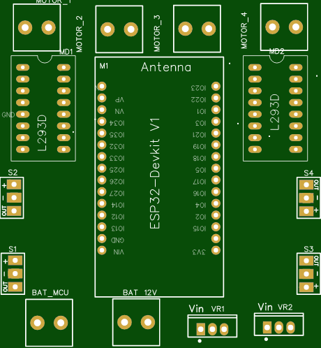
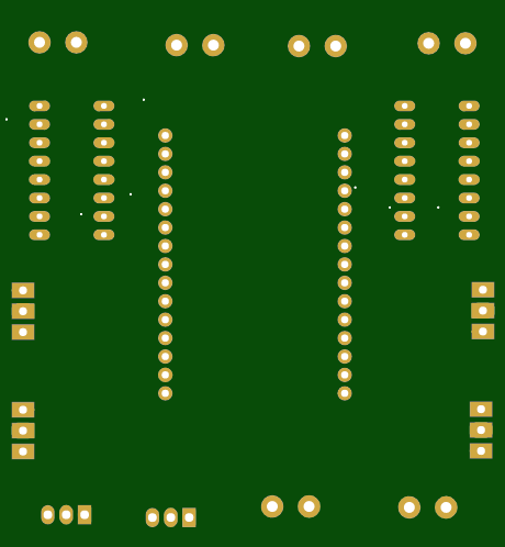
PCB

For the PCB design, I used the EasyEDA web editor and fabricated the PCB using PCBWay. With PCBWay, you get 10 pieces of a 1-2 layer PCB for just $5.
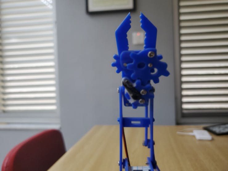
Robot arm assembly
This is the most difficult part of this project. I followed the assembly instructions from Sirut Hobby website. Here are some snapshots to aid your assembly.


Video Demonstration
Motobot-with-Robotic-Arm-Schematic_PCB_Motobot-with-Robotic-Arm-Schematic_2024-10-14
*PCBWay community is a sharing platform. We are not responsible for any design issues and parameter issues (board thickness, surface finish, etc.) you choose.


Raspberry Pi 5 7 Inch Touch Screen IPS 1024x600 HD LCD HDMI-compatible Display for RPI 4B 3B+ OPI 5 AIDA64 PC Secondary Screen(Without Speaker)
BUY NOW


- Comments(3)
- Likes(2)
More by Pius Ndukwu
-
Programmable Mist Maker - XIAO / QT PY Extension
174 0 0 -
RadioHAT - Raspberry Pi radio development platform
185 0 1 -
-
-
-
-
ARPS-2 – Arduino-Compatible Robot Project Shield for Arduino UNO
2768 0 5 -
A Compact Charging Breakout Board For Waveshare ESP32-C3
3276 3 8 -
AI-driven LoRa & LLM-enabled Kiosk & Food Delivery System
3531 2 2


