


|
arduino IDEArduino
|
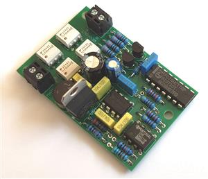
DualPowerBreaker-3C
The Dual DCC Power Breaker (DPB) is intended to protect model railroad layouts from short circuits or overloads, and is designed using readily-available through-hole components only, so that anyone capable of using a soldering iron (and who is comfortable assembling electronic components on to a PCB) can buy the components and build it. The only particular PCB requirement is that it needs to be built using 2oz copper (70 micron), rather than the standard 1oz (35 micron) copper, to handle DCC currents up to 5 amps.
Control of the DPB operational parameters is exercised through the fitted Arduino Nano microcontroller. Parameters can be configured independently for each of the two channels, and allow you to set the current limit for each channel (power district), the delay time after the channel current exceeds the set limit before power is cut off, and the subsequent delay time before the DPB tries to reconnect power to that channel.
After power is cut to either (or both) of the two outputs the DPB will attempt to reapply power automatically after the set delay. If an overload is still present, the DPB will cut off power again, and will continue to cycle through this sequence until the cause of the track overload is removed (or the user cuts off power to the DCC command station or booster at source).
The user can disable the auto-reconnect feature if they wish, and connect a manual pushbutton to either or both channels of the DPB to reapply power to the layout. Such a manual pushbutton can also be used to override a long reconnect delay and switch track power on again. Additionally, there is provision to connect an external LED and alarm sounder to each channel to notify the user when a power break occurs – since the DPB itself will not neccessarily be visible during layout operation.
Specification
Maximum DCC Current through DPB (total of both channels) – 5 amps
(Note – the PCB design will probably handle up to 8 amps, but will get warm)
Channel Trip Current – settable in 0.25 amp steps from 0.25A to 5A
Channel Overload Delay Time – settable in 1 msec steps from 10ms to 255ms
Channel Reconnect Delay Time – settable in 0.25 sec steps from 0.25s to 60s
Full constructional and operational details are published in the June 2025 and July 2025 issues of the (free) Model Railroad Hobbyist magazine - click the links to view.
DualPowerBreaker-3C
*PCBWay community is a sharing platform. We are not responsible for any design issues and parameter issues (board thickness, surface finish, etc.) you choose.


Raspberry Pi 5 7 Inch Touch Screen IPS 1024x600 HD LCD HDMI-compatible Display for RPI 4B 3B+ OPI 5 AIDA64 PC Secondary Screen(Without Speaker)
BUY NOW


- Comments(1)
- Likes(0)
More by Terry Chamberlain
-
Programmable Mist Maker - XIAO / QT PY Extension
433 0 0 -
RadioHAT - Raspberry Pi radio development platform
338 0 1 -
-
-
-
-
ARPS-2 – Arduino-Compatible Robot Project Shield for Arduino UNO
2887 0 6 -
A Compact Charging Breakout Board For Waveshare ESP32-C3
3386 3 8 -
AI-driven LoRa & LLM-enabled Kiosk & Food Delivery System
3716 2 2


