


|
|
ATMEGA328-AUMicrochip
|
x 1 | |
|
|
DRV8251DDARTexas Instruments
|
x 2 | |
|
|
LDL1117S33RSTMicroelectronics
|
x 1 | |
|
|
MCP1703T-5002E/CBMICROCHIP TECHNOLOGY
|
x 1 | |
|
|
Mini-NRF24L01-SMD |
x 1 |

|
arduino IDEArduino
|
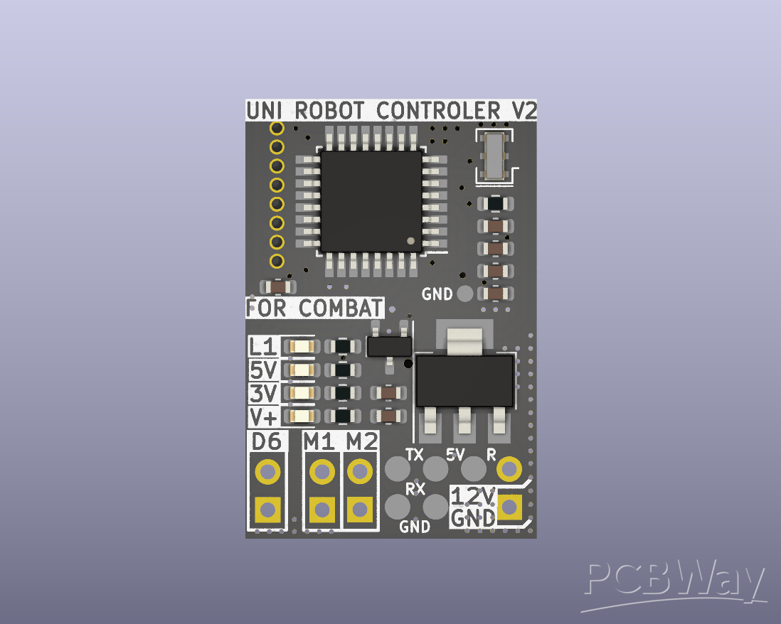
Universal Robot Controller for Combat Robotics 150g
ABOUT THE PROJECT:
For several years I have been building combat robots as a hobby, which led me to take on the challenge of designing my own compact and lightweight robot controller. The goal was to create a board capable of reliably operating robots in the 150-gram class, where every gram and millimeter matters.
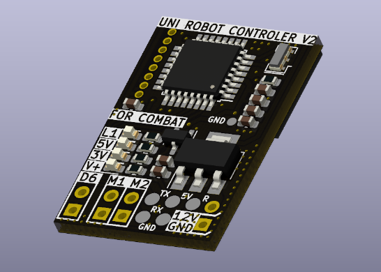
The main focus of this project was minimal size, low weight, and full functionality. I wanted a controller that could be easily installed in almost any combat robot while reducing space usage, overall mass, and complex wiring. The result is a universal combat robot controller PCB measuring just 20x30 mm and weight under 3 grams.
One of the key design goals was to move away from off-the-shelf commercial RC systems, which are commonly used in combat robots. I wanted not only to build something of my own, but also to gain full control over the robot’s behavior. This approach makes it possible to program custom movements, reactions, and even animations tailored to specific combat strategies.
For this reason, the ATmega328AU was chosen as the heart of the PCB. It is a well-known, reliable microcontroller that is easy to program using the Arduino IDE, which significantly speeds up development and testing. Wireless communication is handled by the nRF24L01 radio module — a widely available, proven, and well-documented solution that fits perfectly with the project’s goals of simplicity, flexibility, and reliability.
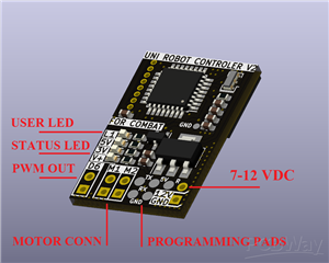
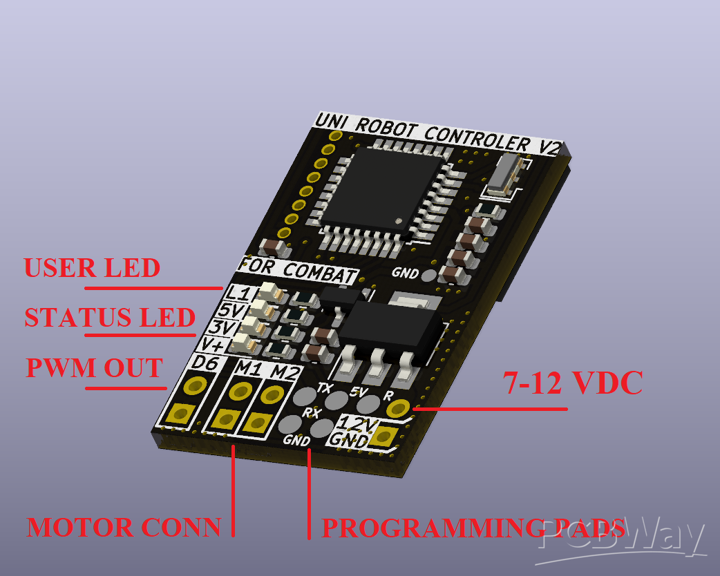
PCB PARAMETERS AND FUNCTIONS:
- UART programming via exposed pogo-pin pads
- Supply voltage: 7–12 V DC (2S–3S LiPo)
- Control of two DC motors with up to 4 A max current
- One PWM output (D6)
- Three power/status indicator LEDs
- One user-programmable LED
- Dimensions: 4 × 20 × 30 mm
- Weight: 3 g (fully assembled)
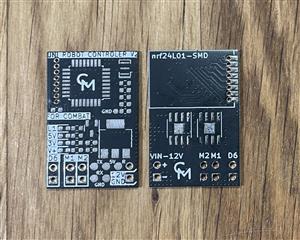
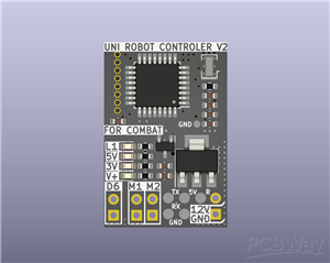
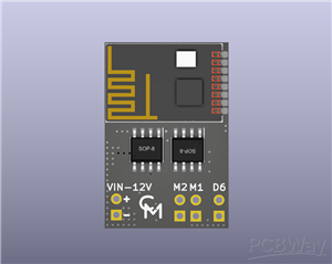
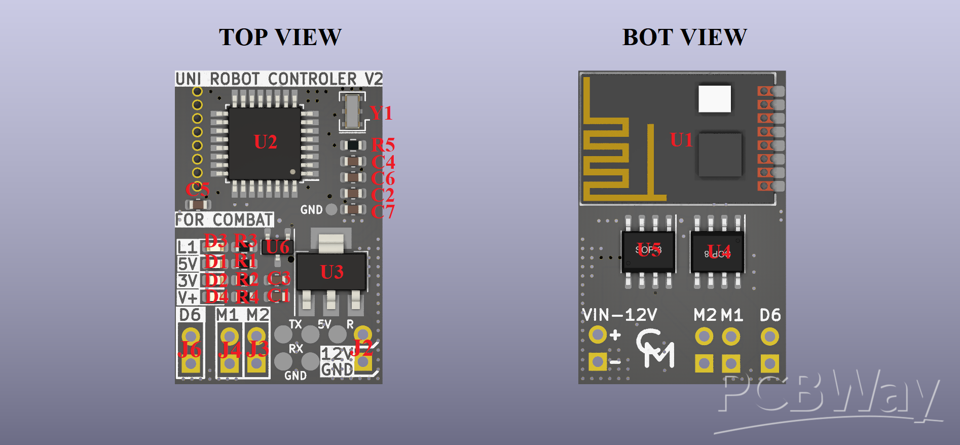
COMPONENTS PLACEMENT AND BOM:
Due to the small dimensions of the PCB, I decided to omit the reference designators for individual components. Therefore, the graphic below includes a description of each component in accordance with the BOM and the electrical schematic. Connector J1 is only an SMD pad intended for programming. I propose leaving connectors J2, J3, J4, and J6 without soldered gold pin headers and using them instead for direct wire soldering.
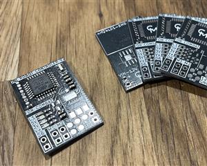
PRODUCTION SPECIFICATION:
This PCB is simple 2-side PCB with 1 OZ copper layer. I made prototype with 1mm FR-4 material thickness. Rest of the PCB parameters matches with basic PCBway capabilities.
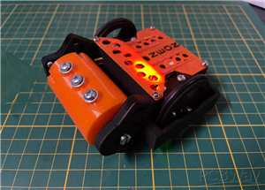
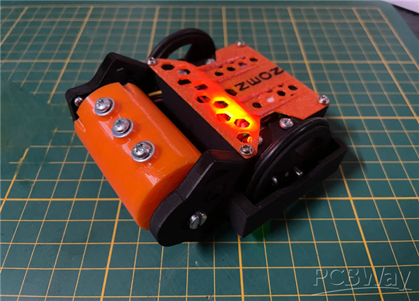
EXAMPLE OF USE IN MY 150G ROBOT - NEON
Universal Robot Controller for Combat Robotics 150g
Project images are for reference only. Actual production is based on the manufacturing files on the project page.
Please review the designer's notes (e.g., PCB thickness) and select the appropriate options.
PCBWay is not responsible
for issues caused by unsuitable parameter selections.
For more important ordering information, please refer to
Read More


Raspberry Pi 5 7 Inch Touch Screen IPS 1024x600 HD LCD HDMI-compatible Display for RPI 4B 3B+ OPI 5 AIDA64 PC Secondary Screen(Without Speaker)
BUY NOW


- Comments(2)
- Likes(1)
 More by Engineer

-
Programmable Mist Maker - XIAO / QT PY Extension
1102 2 1 -
RadioHAT - Raspberry Pi radio development platform
916 0 2 -
-
-
-
-
ARPS-2 – Arduino-Compatible Robot Project Shield for Arduino UNO
3346 0 6 -
A Compact Charging Breakout Board For Waveshare ESP32-C3
3961 3 8 -
AI-driven LoRa & LLM-enabled Kiosk & Food Delivery System
4349 2 2


