


|
Soldering iron |
|

|
Soldering Iron Wire Welding Lead Roll |
The Joystick Hand Controller and DIY Camera Slider
The Joystick Hand Controller makes it possible to control the projects using two-axis values (directions of movement of joystick knob). Also, in this project we made a DIY camera slider and controlled it wirelessly with the Arduino Joystick Hand Controller. Let's take a look at the video on "how it works?".
The Joystick Hand Controller includes a two-axis joystick component. The analog values measured on the X and Y axes are compared with the threshold values determined in the source code and the functions are run. The joystick hand controller acts as a transmitter, it uses the nRF24L01 transceiver module and enables communication wirelessly.
The joystick controller contains three main hardware:

1) Transceiver Module
- nRF24L01+
- Frequency Range 2.4 GHz ISM Band
- Communication Range: 800+ m (line of sight)
The nRF24L01 + transceiver module allows two or more Arduino boards to communicate with each other wirelessly and remotely. A transmitter and a receiver circuit are required to provide communication. An address (array of bytes) is created for two nRF24L01 modules to communicate. It communicates over this address and transfers data. The nRF24L01 module is a bit tricky to use especially since there are many cloned versions in the market. If you are having any problem with getting it work, try adding a 10uF and 0.1uF capacitor in parallel to the Vcc and Ground pins. Also make sure the 3.3V supply is clean and does not have any noise coupled in it.

A popular library called RF24 is used to interface with the nRF24L01 transceiver module. RF24 Arduino Library for nRF24L01+ Module - https://github.com/nRF24/RF24
2) Two-Axis Joystick
When we listen the word “Joystick” we think of Game controllers. If we talk about Electronics there are many useful application of Joystick. These type of module are mostly used in Arduino based DIY projects and Robot Control. As we know, the module gives analog output. We can use a Joystick Module with Arduino, Raspberry Pi and any other Micro-controllers. We just have to connect the axis Pins VRx and VRy to the ADC Pins of the micro-controller.

The output range is fixed for each direction. The below image shows, the value of analog output for X and Y axis based on the movement of Joystick Module in all four directions (+X, -X, +Y, -Y). You will also get some analog value when moving the knob diagonally.
3) Microcontroller
Arduino Pro Mini
3.3V 8 MHz
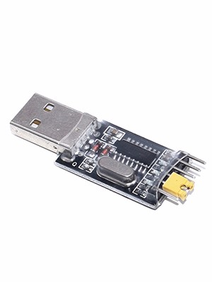
Arduino Pro Mini was developed for applications and installations where space is premium and projects are made as permanent set ups. The Pro Mini does not have a built-in USB input, so a serial converter (FTDI) is used to upload the source code. It is an easy process. For more detail about Arduino Pro Mini - https://www.arduino.cc/en/pmwiki
Prototype (Printed Circuit Board):

A printed circuit board was designed to turn the project into a useful prototype. Printed circuit boards are plates with conductive paths on the surface for mounting electronic circuit components. To get the PCBs, simply upload the shared "Gerber file" to pcbway.com and create an order. High-quality PCBs will arrive in a few days depending on the shipping address.

The Joystick Hand Controller needs a few components. Easy solderable components. Place and solder components according to shared reference designator.
Breadboard Prototype for The Joystick Hand Controller:

I'm attaching a circuit diagram here in case you want to test and experience the Joystick Hand Controller. You can then order a PCB to turn your breadboard circuit into a professional prototype.

Transmitter Source Code:
The Pro Mini does not have a built-in USB input, so a serial converter (FTDI) is used to upload the source code. It is an easy process.
Arduino Pro Mini 3.3V version is used in the project, so make sure to set the power jumper on the FTDI module to 3.3V!
Upload the shared Transmitter source code (https://create.arduino.cc/editor/mertarduinotech) using the FTDI module. Before the source code is uploaded, the board selection should be determined according to the Arduino Pro Mini version (3.3v) used.
DIY Camera Slider (Receiver)

On the Receiver side of the project we made a DIY camera slider and controlled it with the joystick hand controller. You can assign one of the joystick axes (X and Y) to motor direction control and the other to motor speed control.
The A4988 driver for the stepper motor control:
The A4988 is a micro-stepping driver for controlling bipolar stepper motors.
The A4988 provides five different step resolutions: full-step, haft-step, quarter-step, eight-step and sixteenth-step.
It has a potentiometer for adjusting the current output.
Logic voltage is 3 to 5.5 V
Maximum current 2A (with cooling)
Continuous current 1A (without cooling)

A4988 Stepper Driver Pinout:
The VDD and Ground (GND) pins connect to the 3V or 5V of the microcontroller.
The 1A and 1B pins will be connected to one coil of the motor and the 2A and 2B pins to the other coil of the motor.
The VMOT and Ground (GND) connect to power supply from 8V-35V for powering the stepper motor.
Use decoupling capacitor with at least 47 μF for protecting the driver board from voltage spikes.
The Step and Direction (DIR) are the pins use for controlling the motor movements. The Direction pin controls the rotation direction of the motor. The Step pin control the micro-steps of the motor and with each pulse sent to this pin the motor moves one step.
The SLEEP Pin and a logic low puts the board in sleep mode for minimizing power consumption when the motor is not in use.
The RESET pin uses to a predefined Home position. The reset pin is a floating pin. If it is not going to be used in the program, it must be connected to the SLEEP pin to bring it high and enable the board.
Step motor and Driver Connections:
Use the drive in "Full Step Mode" so leave the "3 MS" pins disconnected.
Connect the "Direction" and the "Step" pins of the drive to the pins number 3 and 4 on the "Arduino Board”.
Connect the "Ground" and the "3V" pins to powering the board.
Use a "100μF" capacitor for protecting voltage spikes and "12V, 1.5A" adapter for powering the motor.
Use a "NEMA 17" bipolar Stepper Motor. It's wires A and C will be connected to the pins "1A and 1B" and the B and D wires to the "2A and 2B" pins.
Before connect the motor, should be adjust the current of the driver for the current limits of the motor. It can be do that by adjusting the reference voltage using the potentiometer on the board.
Adjusted the potentiometer and measured 0.6V reference voltage. So the current limiting should be that value of 0.6*2, equal 1.2 A.
Receiver Code:
First, we have to define the Step and Direction pins. The pins number 3 and 4 on the Arduino Board. They are named stepPin and dirPin and the setup section we have to define them as an outputs. Download the DIY Camera Slider Receiver code https://create.arduino.cc/editor/mertarduinotech/
Details for the construction of the DIY camera slider will be shared as soon as possible.
https://create.arduino.cc/editor/mertarduinotech/40e17f04-56c8-4b16-951e-6bb8c9985b41/preview


The Joystick Hand Controller and DIY Camera Slider
Project images are for reference only. Actual production is based on the manufacturing files on the project page.
Please review the designer's notes (e.g., PCB thickness) and select the appropriate options.
PCBWay is not responsible
for issues caused by unsuitable parameter selections.
For more important ordering information, please refer to
Read More


Raspberry Pi 5 7 Inch Touch Screen IPS 1024x600 HD LCD HDMI-compatible Display for RPI 4B 3B+ OPI 5 AIDA64 PC Secondary Screen(Without Speaker)
BUY NOW


- Comments(0)
- Likes(7)
More by MERT KILIC
-
 3D Printed Theo Jansen Style Octopod Robot (Arduino Based)
Hi everyone! In this project, I will show you an amazing eight-legged robot in the Octopod style! It...
3D Printed Theo Jansen Style Octopod Robot (Arduino Based)
Hi everyone! In this project, I will show you an amazing eight-legged robot in the Octopod style! It...
-
 Creative Modular LED Lighting with Magnetic Pogo Pins & Wi-Fi Control
Hi everyone! Welcome to my latest project: a modular, plug-in LED lighting system that is as fun as ...
Creative Modular LED Lighting with Magnetic Pogo Pins & Wi-Fi Control
Hi everyone! Welcome to my latest project: a modular, plug-in LED lighting system that is as fun as ...
-
 Build a simple 3D printed CNC plotter machine
Hi friends, do you remember this Mini CNC Plotter machine that uses hobby stepper motors and a few 3...
Build a simple 3D printed CNC plotter machine
Hi friends, do you remember this Mini CNC Plotter machine that uses hobby stepper motors and a few 3...
-
 Circuit Activity Board - Educational Electronics
Circuit Activity Board – A Hands-On Project to Learn Basic ElectronicsIn this project, we're going t...
Circuit Activity Board - Educational Electronics
Circuit Activity Board – A Hands-On Project to Learn Basic ElectronicsIn this project, we're going t...
-
 Build a Simple 3D Wall Lighting
Hi friends, this project shows how to make and control 3D hexagonal LED lighting panels. The project...
Build a Simple 3D Wall Lighting
Hi friends, this project shows how to make and control 3D hexagonal LED lighting panels. The project...
-
 Robot Sumo Board
Robot-sumo, or pepe-sumo, is a sport in which two robots attempt to push each other out of a circle ...
Robot Sumo Board
Robot-sumo, or pepe-sumo, is a sport in which two robots attempt to push each other out of a circle ...
-
 ESP32 Mecanum Wheels Robot and Bluetooth Gamepad Controller
In this project we will see how to make an ESP32 Mecanum Wheels Robot which is capable of moving in ...
ESP32 Mecanum Wheels Robot and Bluetooth Gamepad Controller
In this project we will see how to make an ESP32 Mecanum Wheels Robot which is capable of moving in ...
-
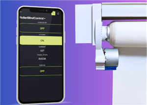
 DIY Motorized WiFi Roller Blind - ESP8266 & Blynk
In this project we will see how to control a roller blind via a smartphone application. The reason w...
DIY Motorized WiFi Roller Blind - ESP8266 & Blynk
In this project we will see how to control a roller blind via a smartphone application. The reason w...
-
 Pet Feeder Controlled Via WiFi - ESP8266
How It Works?As you can see, a 3D design was used for the pet feeder. ESP8266-based Wemos D1 Mini bo...
Pet Feeder Controlled Via WiFi - ESP8266
How It Works?As you can see, a 3D design was used for the pet feeder. ESP8266-based Wemos D1 Mini bo...
-
 ESP8266 Two Wheel Robot (NodeMCU and Stepper Motor)
Generally, robot cars are built on a chassis with 2 DC motor wheels and a bovine wheel. While surfin...
ESP8266 Two Wheel Robot (NodeMCU and Stepper Motor)
Generally, robot cars are built on a chassis with 2 DC motor wheels and a bovine wheel. While surfin...
-
 3D Printed Rotating Table Board with Arduino Nano and 28BYJ-48 Stepper Motor
This project shows how to make a 3D printed Rotating Table using Arduino and a hobby stepper motor. ...
3D Printed Rotating Table Board with Arduino Nano and 28BYJ-48 Stepper Motor
This project shows how to make a 3D printed Rotating Table using Arduino and a hobby stepper motor. ...
-
 Hand Gesture Controller for Robotic
The hand gesture controller makes it possible to control applicat...
Hand Gesture Controller for Robotic
Hand Gesture Controller for RoboticThe hand gesture controller makes it possible to control applicat...
-
 How To Make DIY Remote Control Hoverboat at Home
In this video, I showed you how to make your own hoverboat from materials available at home and chea...
How To Make DIY Remote Control Hoverboat at Home
In this video, I showed you how to make your own hoverboat from materials available at home and chea...
-
 How to Make DIY Arduino Gesture Control Robot at Home
Parts Required for Receiver (Tank):1) Robot Tank Chassis - https://bit.ly/3j8y2Q52) Arduino Nano V3 ...
How to Make DIY Arduino Gesture Control Robot at Home
Parts Required for Receiver (Tank):1) Robot Tank Chassis - https://bit.ly/3j8y2Q52) Arduino Nano V3 ...
-
 DIY Circuit Activty Board with Paperclips | MAKER | STEM
You can be creative and design your own circuit and add different sensors (other LEDs...). The idea ...
DIY Circuit Activty Board with Paperclips | MAKER | STEM
You can be creative and design your own circuit and add different sensors (other LEDs...). The idea ...
-
 ATtiny85 Wearable Activity Tracking Watch
How to make the wearable activity tracking watch? This is a wearable gadget designed to vibrate when...
ATtiny85 Wearable Activity Tracking Watch
How to make the wearable activity tracking watch? This is a wearable gadget designed to vibrate when...
-
 DIY Motorized Roller Blind with ESP32-S3 | WiFi Control, 3D Printed Gear & Blynk Cloud
This project is an updated version of my previous Motorized Roller Blind, which reached nearly 300,0...
DIY Motorized Roller Blind with ESP32-S3 | WiFi Control, 3D Printed Gear & Blynk Cloud
This project is an updated version of my previous Motorized Roller Blind, which reached nearly 300,0...
-
 How to Build a Motorized 3D Scanning Turntable for Your Phone
In this project, I’ll show you how to make a simple motorized turntable for 3D scanning. It has thre...
How to Build a Motorized 3D Scanning Turntable for Your Phone
In this project, I’ll show you how to make a simple motorized turntable for 3D scanning. It has thre...
-
Programmable Mist Maker - XIAO / QT PY Extension
1061 2 1 -
RadioHAT - Raspberry Pi radio development platform
861 0 2 -
-
-
-
-
ARPS-2 – Arduino-Compatible Robot Project Shield for Arduino UNO
3322 0 6 -
A Compact Charging Breakout Board For Waveshare ESP32-C3
3930 3 8 -
AI-driven LoRa & LLM-enabled Kiosk & Food Delivery System
4316 2 2


