


Autonomous Flight Control System - AFCS MK5 B
AFCS Mk5 is a compact, AIoT-enabled flight computer for small rockets. It combines sensor fusion, physics-based calculations, and feedback control to actively stabilize a rocket while logging telemetry for analysis.
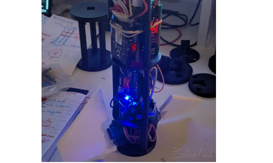
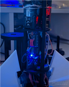
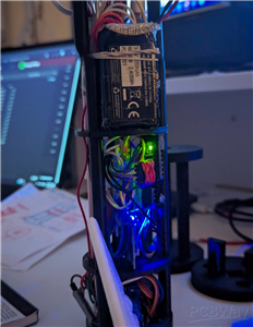
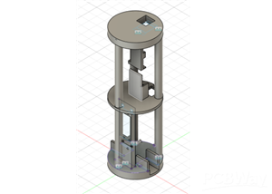
Autonomous Flight Control System MK5 or AFCS MK5 is a model rocket AIoT-enabled flight computer that is compact and runs on an on-board autonomous flight software that is designed to allow for complete guidance and full roll control for experimental model rockets, as it integrates physics-based calculations, sensor fusion, and active feedback control in-order to stabilize a model rocket. This project had gone through various iterations from MK1, MK2, MK3, MK4 and lastly MK5. From an inspiration by having a burning desire to push the realm of rocketry beyond the limits of basic simple passive stability, hence this project fully integrates together advanced avionics into simple PCB that is designed for measuring flight data such as orientation, servo positions, altitude from sea-level and in correcting instability in real-time, while providing full telemetry to the user after the flight.
I had set out to build a reliable system that could sense the motions and forces that are occurring in real-time on the rocket, provide an instant reactionary action and would fit in a lightweight airframe.
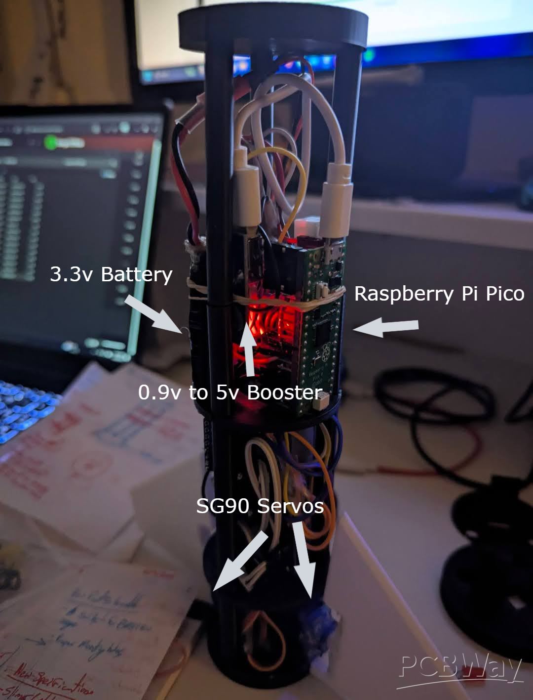
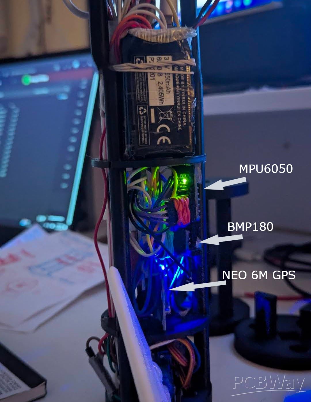
Fundamentally the AFCS MK5, relies on a 9-Axis MPU6500 IMU to combine Accelerometer and Gyro data via a Common filter to provide reliable pitch, roll, and yaw (after creating a hard-coded yaw reference) data all during powered maneuvers. Altitude data via altimeter and peak altimeter sensing comes from a BMP180 barometric sensor. Velocity and location data comes from a NEO-6M GPS module. All data is written to an auto-incrementing CSV file.
Other than its functionalities and capabilities, AFCS Mk5 also holds great educational value. Being based on real-world aerospace systems such as inertial data fusion, PID control, telemetry data logging, and events detection, it provides a great learning area for educational institutions to teach basic principles related to rocket science, physics, embedded systems, and control systems, as well as having the ability to develop more complex systems while keeping cost low. In this context, it would be very educational for students in a classroom environment to be able to learn about areas such as acceleration, angular velocity, aerodynamics, as well as feedback control systems by observing them in their actual use in flight. In this context, it would be very educational to be able to learn about areas such as graphing data from logged telemetry data to observe theoretical systems in their actual hardware form.
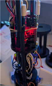
Based on this live orientation data, AFCS Mk5 controls two high-speed SG90 servos coupled to 2x sophisticated fins. The PID algorithm quickly analyzes how far the rocket deviates from its desired orientation and instructs the servos to control the angles of the fins to correct roll and pitch errors in mere milliseconds. The system is also redundancy-minded allowing for undisrupted data collection if any sensor loses connection or fails. In such situations, AFCS Mk5 automatically continues to collect data from other sensors and even attempts in reconnecting to disconnected sensors in the background.
Additionally, the code for the entire autonomous flight controller is available on my GitHub under AFCS MK5.
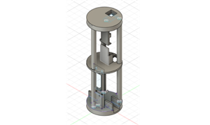
The board also contains functionality to determine critical events of flight such as burn-out, apogee, burn-out, and landing. All these features form the framework for implementing additional capabilities such as parachute deployment and management of multiple stages. In general, I aimed to ensure that AFCS Mk5 would be lightweight and amenable to prototyping via services like PCBWay and durable enough to allow for rapid development and testing. The completion of AFCS Mk5 represents an incredible milestone in pursuing my ultimate objective to build reusable and guided rockets as well as cost-effective control boards for aerospace applications. This overall allows smalls to medium sized rockets to be fully controlled with a cheap open-source solution to demonstrate complex capabilities not seen in current solutions.
AFCS MK5 Autonomous Code Break Down with Physics and Math:
1. Imports and Libraries
import math, os
from machine import I2C, Pin, PWM
from time import ticks_us, ticks_diff, ticks_ms, sleep_ms
from mpu6500 import MPU6500
import bmp180
math: For trigonometry and square roots used in orientation calculations.
os: To create new log files for each flight.
machine: Hardware interface (I2C, GPIO, PWM).
time: Provides microsecond/millisecond timing for integration and velocity.
mpu6500 & bmp180: Drivers for the IMU (gyroscope + accelerometer) and barometer.
Physics context: Sensors provide raw measurements (acceleration, angular velocity, pressure). These measurements must be transformed mathematically to derive an orientation, altitude, and velocity.
2. LED Status Indicator
led = Pin(25, Pin.OUT)
def blink(times, delay_ms=200):
for _ in range(times):
led.on()
sleep_ms(delay_ms)
led.off()
sleep_ms(delay_ms)
LED provides real-time feedback on sensor status.
Blinking patterns signal errors or reconnections, which is a critical part of robust AIoT design.
3. I2C Bus Initialization
i2c0 = I2C(0, sda=Pin(0), scl=Pin(1), freq=400_000)
i2c1 = I2C(1, scl=Pin(3), sda=Pin(2), freq=100000)
i2c0: Connects to the IMU at high speed (400 kHz).
i2c1: Connects to the barometer at standard speed (100 kHz).
Separating buses avoids interference, improving reliability and AIoT resilience.
4. Sensor Initialization
def init_mpu():
while True:
try:
mpu = MPU6500(i2c0)
print("✅ MPU6500 connected.")
return mpu
except:
blink(5,100)
sleep_ms(500)
def init_bmp():
while True:
try:
bmp = bmp180.BMP180(i2c1)
bmp.oversample_sett = 2
bmp.sea_level_pressure = 101325
return bmp
except:
blink(1,300)
sleep_ms(1000)
Implements automatic reconnection, a key principle in AIoT.
Ensures continuous data collection, preventing flight loss due to sensor failure.
5. Gyroscope Calibration
def calibrate_gyro(samples=500, delay_ms=5):
gx_offset = gy_offset = gz_offset = 0
for _ in range(samples):
gx, gy, gz = mpu.gyro
gx_offset += gx; gy_offset += gy; gz_offset += gz
sleep_ms(delay_ms)
return gx_offset/samples, gy_offset/samples, gz_offset/samples
Gyroscopes have bias or drift, the averaging readings while stationary gives zero-rate offsets.
Corrected angular velocity:
ω_corrected = ω_raw - bias
This is crucial for accurate integration over time to compute orientation.
6. Complementary Filter – Orientation Tracking
roll = pitch = yaw = 0.0
alpha = 0.98
last = ticks_us()
Tracks roll, pitch, yaw in degrees.
Alpha balances trust: gyro vs accelerometer.
def get_accel_angles(ax, ay, az):
norm = math.sqrt(ax*ax + ay*ay + az*az)
ax /= norm; ay /= norm; az /= norm
roll_acc = math.atan2(ay, az)
pitch_acc = math.atan2(-ax, math.sqrt(ay*ay + az*az))
return math.degrees(roll_acc), math.degrees(pitch_acc)
Physics / Math:
Accelerometer measures gravitational vector plus dynamic acceleration:
a = [a_x, a_y, a_z] = g + a_dynamic
Pitch and roll are derived using basic trigonometry:
roll = arctan(a_y / a_z)
pitch = arctan(-a_x / sqrt(a_y^2 + a_z^2))
Complementary Filter Equation:
angle = α * (angle + ω * dt) + (1 - α) * accel_angle
Gyro integrates angular velocity ω\omegaω over time. The accelerometer corrects long-term drift.
7. Servo Control (Actuators)
servo1 = PWM(Pin(9)); servo2 = PWM(Pin(21))
servo1.freq(50); servo2.freq(50)
def angle_to_duty(angle):
angle = max(135, min(225, angle))
return int((angle / 180.0) * 3276) + 3277
Servo output implements the control action of the AIoT system.
Control logic (yaw correction):
θ_servo = 180 - (desired_yaw - current_yaw)
This acts like a proportional control loop to reduce yaw error.
8. Barometer – Altitude and Velocity
BMP180 measures pressure, which is converted to altitude using the barometric formula:
h = (R * T / g) * ln(P0 / P)
Velocity estimation:
v = Δh / Δt
Used to detect apogee (maximum altitude) for data logging or in triggering events, such as parachute development.
9. Flight Logging
log_file.write("time,altitude,velocity,yaw,servo1,servo2,setpoint,apogee,mpu_status,bmp_status\n")
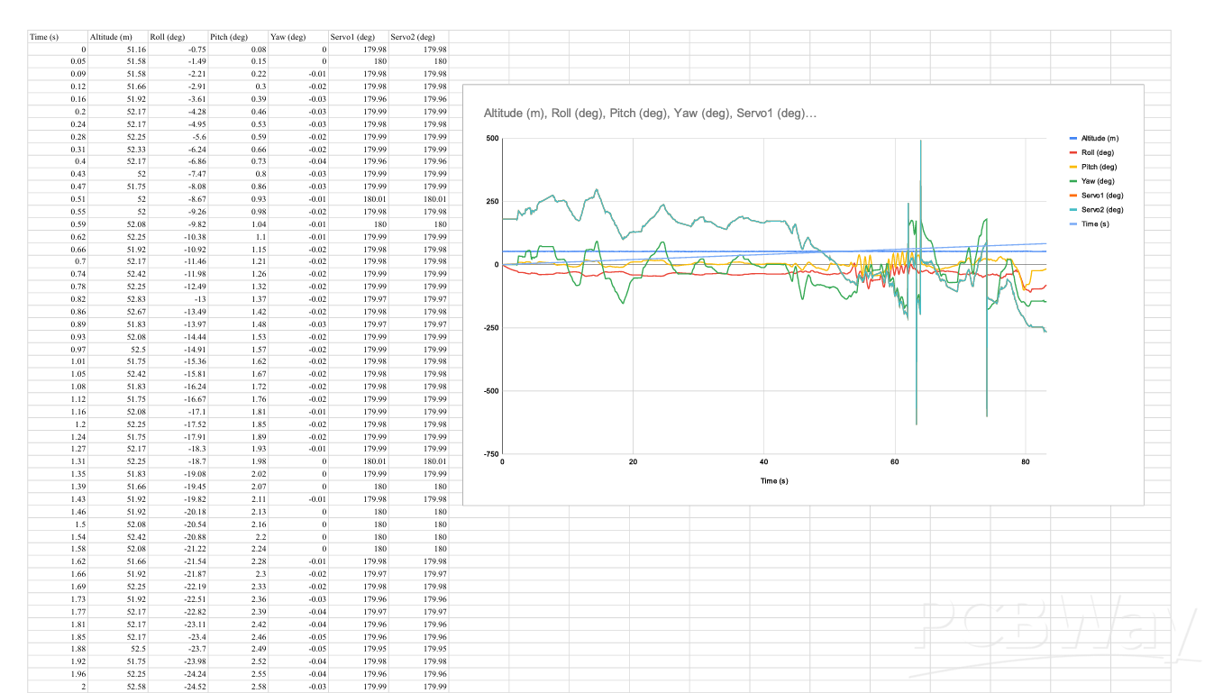
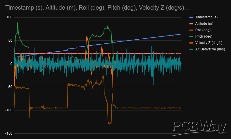
CSV log stores all critical Telemetry data: orientation, actuator commands, sensor health.
Allows post-flight analysis, data visualization, and improvement of control algorithms to a user’s preference.
10. Main Loop – AIoT Control
Time step calculation:
dt = (current_time - last_time) / 1e6
Sensor reading (fault-tolerant):
IMU: ax, ay, az, gx, gy, gz
Barometer: pressure → altitude
Orientation fusion:
Gyro integration:
roll_gyro = roll + ω_x * dt
pitch_gyro = pitch + ω_y * dt
yaw_gyro = yaw + ω_z * dt
Accelerometer correction based on using a complementary filter.
Servo actuation:
Calculate yaw error:
yaw_error = desired_yaw - current_yaw
Allows for servo angles to be updated proportionally.
Velocity computation:
v = (h_current - h_previous) / dt
Apogee detection:
Compare current altitude to max recorded altitude.
Trigger event when descending by 0.5 m from max.
Logging and flush:
Write telemetry every cycle.
Flush to storage every 10 seconds for safety.
Loop delay:
10 ms → ~100 Hz update rate.
11. Physics Summary of the AFCS autonomous program
Orientation: Calculated using gyro integration and accelerometer correction.
Velocity: Derived from Δaltitude / Δtime.
Servo correction: Acts as torque to counter yaw disturbances.
Apogee detection: Uses derivative of altitude to identify peak flight point.
import math, os
from machine import I2C, Pin, PWM
from time import ticks_us, ticks_diff, ticks_ms, sleep_ms
from mpu6500 import MPU6500
import bmp180

# === LED Setup ===
led = Pin(25, Pin.OUT)

def blink(times, delay_ms=200):
    for _ in range(times):
        led.on()
        sleep_ms(delay_ms)
        led.off()
        sleep_ms(delay_ms)

# === I2C Init ===
i2c0 = I2C(0, sda=Pin(0), scl=Pin(1), freq=400_000)  # MPU6500
i2c1 = I2C(1, scl=Pin(3), sda=Pin(2), freq=100000)   # BMP180

# === Sensor Initialization with Retry ===
def init_mpu():
    while True:
        try:
            mpu = MPU6500(i2c0)
            print("✅ MPU6500 connected.")
            return mpu
        except:
            print("❌ MPU6500 connection failed. Retrying...")
            blink(5, 100)
            sleep_ms(500)

def init_bmp():
    while True:
        try:
            bmp = bmp180.BMP180(i2c1)
            bmp.oversample_sett = 2
            bmp.sea_level_pressure = 101325
            print("✅ BMP180 connected.")
            return bmp
        except:
            print("❌ BMP180 connection failed. Retrying...")
            blink(1, 300)
            sleep_ms(1000)

mpu = init_mpu()
bmp = init_bmp()
led.on()  # solid ON when both OK

# === Gyro Calibration ===
def calibrate_gyro(samples=500, delay_ms=5):
    print("Calibrating gyro... Keep sensor still.")
    gx_offset = gy_offset = gz_offset = 0.0
    for _ in range(samples):
        gx, gy, gz = mpu.gyro
        gx_offset += gx; gy_offset += gy; gz_offset += gz
        sleep_ms(delay_ms)
    return gx_offset / samples, gy_offset / samples, gz_offset / samples

gx_bias, gy_bias, gz_bias = calibrate_gyro()

# === Complementary Filter Setup ===
roll = pitch = yaw = 0.0
alpha = 0.98
last = ticks_us()

# === Desired Yaw ===
desired_yaw = 0.0
yaw_updated = False

# === Servo Setup ===
servo1 = PWM(Pin(9)); servo2 = PWM(Pin(21))
servo1.freq(50); servo2.freq(50)

def angle_to_duty(angle):
    angle = max(135, min(225, angle))
    return int((angle / 180.0) * 3276) + 3277

servo1.duty_u16(angle_to_duty(180))
servo2.duty_u16(angle_to_duty(180))

# === Accelerometer Angles ===
def get_accel_angles(ax, ay, az):
    norm = math.sqrt(ax*ax + ay*ay + az*az)
    if norm == 0: return 0.0, 0.0
    ax /= norm; ay /= norm; az /= norm
    roll_acc = math.atan2(ay, az)
    pitch_acc = math.atan2(-ax, math.sqrt(ay*ay + az*az))
    return math.degrees(roll_acc), math.degrees(pitch_acc)

# === Flight Log Setup ===
def next_log_filename():
    n = 1
    while True:
        fname = f"flight{n}.csv"
        if fname not in os.listdir():
            return fname
        n += 1

log_filename = next_log_filename()
log_file = open(log_filename, "w")
log_file.write("time,altitude,velocity,yaw,servo1,servo2,setpoint,apogee,mpu_status,bmp_status\n")
log_file.flush()
print(f"📂 Logging to {log_filename}")

last_save = ticks_ms()
apogee_reached = False
max_alt = -1e9

# For velocity calc
prev_alt = None
prev_t = ticks_us()

boot_time = ticks_us()

# === Main Loop ===
while True:
    now = ticks_us()
    dt = ticks_diff(now, last) / 1_000_000
    last = now
    if dt <= 0 or dt > 0.1: dt = 0.01

    elapsed = ticks_diff(now, boot_time) / 1_000_000

    # Update yaw setpoint after 15s
    if elapsed >= 15 and not yaw_updated:
        desired_yaw += 50
        yaw_updated = True
        print(f"⏱ 15s — desired_yaw set to {desired_yaw}°")

    # --- Sensor Reads with fail tolerance ---
    mpu_status = "OK"
    bmp_status = "OK"

    altitude_val = "N/A"
    velocity_val = "N/A"

    # MPU
    try:
        ax, ay, az = mpu.acceleration
        gx, gy, gz = mpu.gyro
    except:
        print("⚠️ MPU read failed.")
        blink(5, 100)
        mpu_status = "DISCONNECTED"
        mpu = init_mpu()
        mpu_status = "RECONNECTED"
        ax = ay = az = gx = gy = gz = None

    # BMP
    try:
        bmp.measure()
        altitude = bmp.altitude
        altitude_val = f"{altitude:.2f}"
    except:
        print("⚠️ BMP180 read failed.")
        blink(1, 300)
        bmp_status = "DISCONNECTED"
        bmp = init_bmp()
        bmp_status = "RECONNECTED"
        altitude = None

    # LED health
    led.on() if mpu_status=="OK" and bmp_status=="OK" else led.off()

    # Gyro/Accel fusion
    if ax is not None:
        gx -= gx_bias; gy -= gy_bias; gz -= gz_bias
        gx_deg = math.degrees(gx); gy_deg = math.degrees(gy); gz_deg = math.degrees(gz)
        roll_acc, pitch_acc = get_accel_angles(ax, ay, az)
        roll_gyro = roll + gx_deg * dt
        pitch_gyro = pitch + gy_deg * dt
        yaw += gz_deg * dt
        if yaw > 180: yaw -= 360
        elif yaw < -180: yaw += 360
        roll = alpha * roll_gyro + (1 - alpha) * roll_acc
        pitch = alpha * pitch_gyro + (1 - alpha) * pitch_acc

    # Yaw control
    yaw_error = max(-90, min(90, desired_yaw - yaw))
    servo1_angle = 180 - yaw_error
    servo2_angle = 180 - yaw_error
    servo1.duty_u16(angle_to_duty(servo1_angle))
    servo2.duty_u16(angle_to_duty(servo2_angle))

    # Velocity calculation
    dt_alt = ticks_diff(now, prev_t)/1_000_000
    if altitude is not None and prev_alt is not None and dt_alt>0:
        velocity = (altitude - prev_alt)/dt_alt
        velocity_val = f"{velocity:.2f}"
    if altitude is not None:
        prev_alt = altitude
        prev_t = now

    # Apogee detection
    if altitude is not None:
        if altitude > max_alt:
            max_alt = altitude
        elif altitude < max_alt - 0.5 and not apogee_reached:
            apogee_reached = True
            print("🚀 Apogee detected!")

    apogee_flag = "APOGEE" if apogee_reached else ""

    # Log data
    log_file.write(f"{elapsed:.2f},{altitude_val},{velocity_val},{yaw:.2f},{servo1_angle:.1f},{servo2_angle:.1f},{desired_yaw:.2f},{apogee_flag},{mpu_status},{bmp_status}\n")

    # Flush every 10s
    if ticks_diff(ticks_ms(), last_save) >= 10000:
        log_file.flush()
        last_save = ticks_ms()
        print("💾 Data flushed to storage")

    sleep_ms(10)
Autonomous Flight Control System - AFCS MK5 B
*PCBWay community is a sharing platform. We are not responsible for any design issues and parameter issues (board thickness, surface finish, etc.) you choose.


Raspberry Pi 5 7 Inch Touch Screen IPS 1024x600 HD LCD HDMI-compatible Display for RPI 4B 3B+ OPI 5 AIDA64 PC Secondary Screen(Without Speaker)
BUY NOW


- Comments(0)
- Likes(1)
More by Heer Patel
-
 Autonomous Flight Control System - AFCS MK5 B
AFCS Mk5 is a compact, AIoT-enabled flight computer for small rockets. It combines sensor fusion, ph...
Autonomous Flight Control System - AFCS MK5 B
AFCS Mk5 is a compact, AIoT-enabled flight computer for small rockets. It combines sensor fusion, ph...
-
 Breakthrough Model Rocket
This project harnesses the power of 3D printing to revolutionize model rocketry, by making it more a...
Breakthrough Model Rocket
This project harnesses the power of 3D printing to revolutionize model rocketry, by making it more a...
-
 AFCS-MK5 (Autonomous Flight Control System )
Autonomous Flight Control System - AFCS MK5This was previously the APEX Flight Computer, however it ...
AFCS-MK5 (Autonomous Flight Control System )
Autonomous Flight Control System - AFCS MK5This was previously the APEX Flight Computer, however it ...
-
Programmable Mist Maker - XIAO / QT PY Extension
171 0 0 -
RadioHAT - Raspberry Pi radio development platform
179 0 1 -
-
-
-
-
ARPS-2 – Arduino-Compatible Robot Project Shield for Arduino UNO
2765 0 5 -
A Compact Charging Breakout Board For Waveshare ESP32-C3
3273 3 8 -
AI-driven LoRa & LLM-enabled Kiosk & Food Delivery System
3527 2 2


