


|
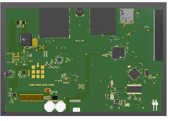
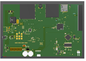
Altium DesignerAltium Designer
|
|

|
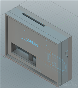
Autodesk Fusion 360Autodesk
|
The Engineering Tablet
Many devices now-a-days that are used for engineering purposes are already pre-programmed and have no flexibility. They use proprietary software and hardware for different purposes. If you needed an oscilloscope for PCIe, that analyzer is designed to do that and nothing else. The hardware inside and the software that is flashed onto it are not usually public knowledge. Certainly, with microcontrollers and FPGAs, the user can program them to do whatever the engineer wants, but those are not industrial applications for specific usage (PCIe logic analyzer). This tablet is designed to bridge the gap between user and producer. The Engineering Tablet is a user-friendly device that is open source with a built-in RTOS. Users are able to use the tablet as is, create their own RTOS, or even program the tablet to their needs. To protect the tablet from any user problems (primarily regarding the power) care was taken to ensure that the entire tablet had flexibility.
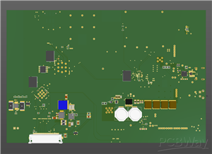
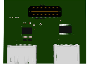
This is a brief description as a more detailed datasheet is provided to this entry. The Engineering Tablet is a customizable board that can be used for remote control, location services and entertainment, centered around a Nordic nRF9151. The dual core debugger, Nordic nRF5340, is used for both programming and additional wireless features. The tablet is powered via USB-C Power Delivery only to keep the weight light (no battery). It is capable of handling up to 100 W (20V/5A). There are several antennae that range from 5G wireless (SIM card slot included) to an NFC antenna. The user can live stream data from anywhere, there is a signal, to a lab somewhere. The tablet consists of several RAM chips and storage to ensure any design, the RTOS it ships with, or custom code, can run without any problem. In case more memory is needed, there is a SD card slot to allow for additional storage. As this is a tablet, there is of course a screen. The screen is capacitive touch 1280x800. The graphics are done via dedicated graphics controller, BridgeTek BT817. A microphone and speaker are also attached to allow for calls out in the field where there might be no Wi-Fi.
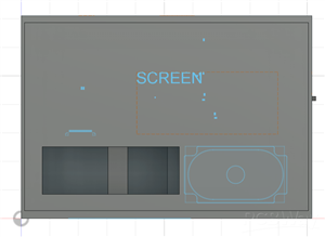
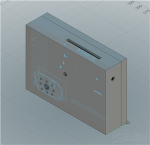
The datasheet included consists of all needed functionality the board has, the parts, how the RTOS works and how the tablet should ideally be used. Please refer to that more additional information. What the datasheet does not include is all the microcontrollers, GPU, memory and other peripheral specific datasheets and what registers and data are being sent. To make a complete system, a case was created to demonstrate how the board would fit. The case holds the board, speaker and screen. USB-C and the reset button are extended out via large extrusions; for example, the reset button has an extension from the board to the case and extends out a bit from the case and would be allowed to rest on the button (not held on or supported) to not put too much weight on the button (to break it) and not get knocked around accidentally (via support column pushing it). The USB-C connector is a long extension that would fit into the socket on the board and extend to the case to allow the reach for the power and debugging/programming. In addition, the case has some holes for allowing the antenna signals to reach outside without having to rely solely on penetrating the case. There are also holes for the speaker for the sound to escape. Finally, the case has a wide slot for SIM card, SD card, microphone and cooling. There is text on the case to tell the user where each thing is.
In all realization, this entry is coming in at the end of the acceptance period. The reason for this is because it was created by only me. I created the entire board and the case the PCB and extensions come in. I hope it can get a nice reception.
The Engineering Tablet
Project images are for reference only. Actual production is based on the manufacturing files on the project page.
Please review the designer's notes (e.g., PCB thickness) and select the appropriate options.
PCBWay is not responsible
for issues caused by unsuitable parameter selections.
For more important ordering information, please refer to
Read More


Raspberry Pi 5 7 Inch Touch Screen IPS 1024x600 HD LCD HDMI-compatible Display for RPI 4B 3B+ OPI 5 AIDA64 PC Secondary Screen(Without Speaker)
BUY NOW


- Comments(0)
- Likes(1)
- 1 USER VOTES
- YOUR VOTE 0.00 0.00
-
10design
-
10usability
-
10creativity
-
10content
More by Engine er
-
Programmable Mist Maker - XIAO / QT PY Extension
1036 2 1 -
RadioHAT - Raspberry Pi radio development platform
840 0 2 -
-
-
-
-
ARPS-2 – Arduino-Compatible Robot Project Shield for Arduino UNO
3296 0 6 -
A Compact Charging Breakout Board For Waveshare ESP32-C3
3914 3 8 -
AI-driven LoRa & LLM-enabled Kiosk & Food Delivery System
4292 2 2


