


|
arduino IDEArduino
|
|

|
Android StudioGoogle LLC
|
|

|
Visual Studio CodeMicrosofe
|
|

|
Python 3.9Python Community
|
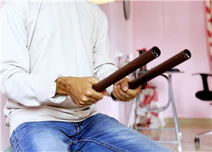
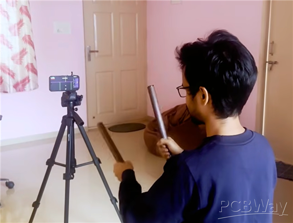
Space Drums - Open Source Air Drums
Welcome to SpaceDrums, my open-source air-drumming system that maps out a full, invisible 3D drum kit around your body using low-cost hardware and computer vision. Instead of hitting physical pads, the system uses artificial intelligence to dynamically anchor six distinct playable zones: Hi-Hat, Snare, Floor Tom, Crash & Ride cymbals, and a Kick Drum, giving you a massive percussion setup that requires zero floor space.
Here is a clear, step-by-step guide to building your own set from scratch.
Bill of Materials (BOM)
Electronics & Sensors
3x ESP32-S3 Development Modules: Selected for native USB support, dual-core processing efficiency, and built-in Wi-Fi capabilities.
3x Adafruit LSM6DS3TR-C IMUs: A 6-Degrees-of-Freedom Inertial Measurement Unit housing an integrated accelerometer and gyroscope.
3x Lithium-ion Batteries: Recommended capacity ~2000 mAh to ensure continuous runtime.
3x TP4056 USB-C Charging Boards: Standard 5V linear chargers to handle safe battery replenishment.
3x Miniature Slide Switches: SPDT toggle switches for manual power rails.
1x FTDI USB-to-Serial Adapter: Vital debug tool used as a hardware backup for serial flashing.
Mechanical Frame & Assembly Tools
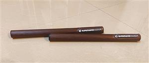
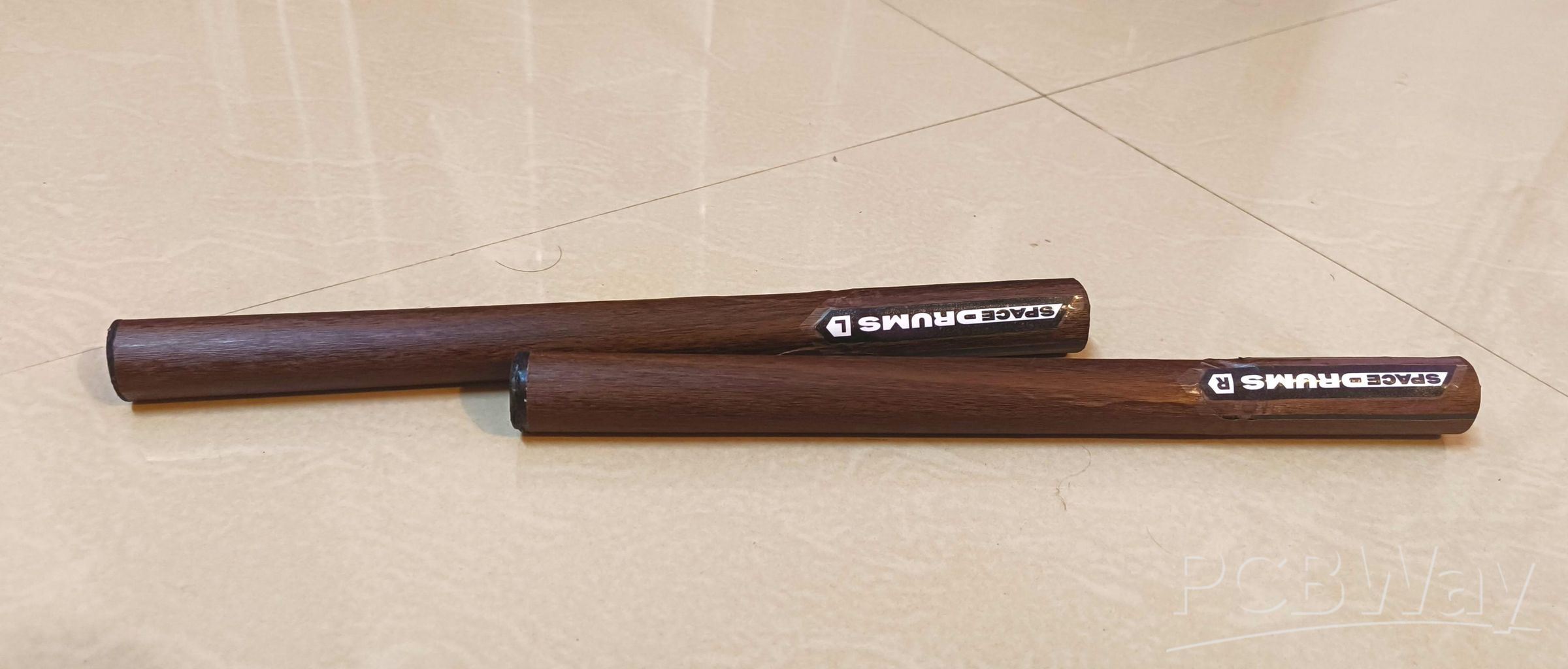
1-inch Diameter PVC Pipe: Cut into two 12-inch sections to house the internal drumstick assemblies.
Wood-Finish Adhesive Vinyl Wrap: For aesthetic finishing of the PVC stick exteriors.
Soldering station, lead-free solder, wire strippers, and high-strength adhesive/foam tape.
Step 1: System Architecture Design
The initial idea was relying purely on a self-contained motion sensor inside a stick. But after months of research, I realized to achieve accurate playability, a hybrid network-and-vision architecture was needed.
- The Accelerometer (Hit Detection): Measures raw G-forces. When the drumstick stops abruptly mid-air, it experiences a sharp spike in negative G-force. The microchip monitors this threshold to mark the exact millisecond of a strike.
- The Gyroscope (Rotational Vectoring): Tracks relative angular changes. By computing the pitch and yaw angles relative to a known start vector, the stick knows if you are angled left, right, up, or down.
- The Processing Pipeline: The ESP32 collects these data packets and streams them instantaneously over local Wi-Fi via UDP port 5556 to an orchestration server
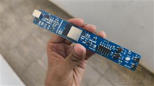
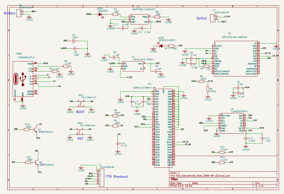
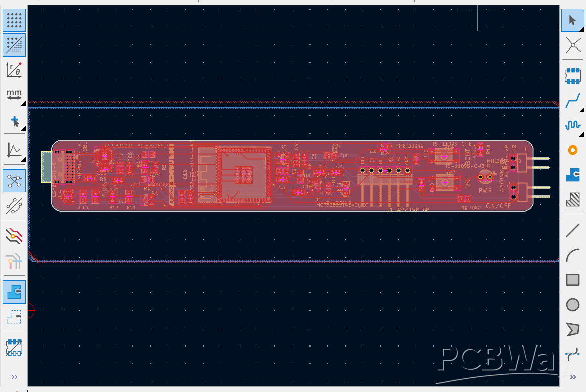
Step 2: Custom PCB & Flash Diagnostics
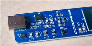
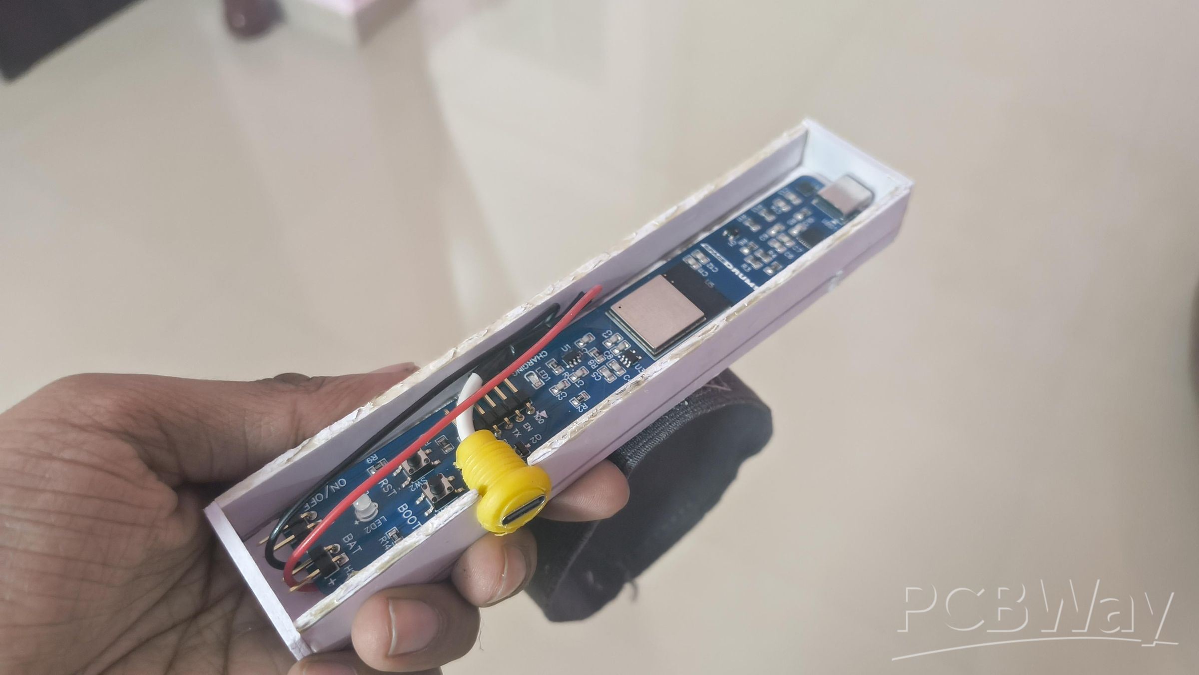
Shoving loose components into a fast-moving tube causes immediate mechanical failure, short circuits, and broken connections due to high impact forces. To solidify the system, I designed a custom Printed Circuit Board (PCB) using KiCad.
Hardware Design Precautions
When laying out traces in KiCad, always plan for interface failures. My initial run suffered from a routing error on the native ESP32-S3 USB-C differential lines, rendering direct USB flashing inoperable. To prevent this and the boards from becoming electronic waste, I exposed TX/RX test pads and an explicit hardware BOOT button into the design.
Flashing Recovery Protocol
If your board fails to mount via standard USB connection:
- Connect an external FTDI USB-to-Serial adapter to the host computer.
- Cross-wire the data lines: Route the adapter's TX pin to the PCB's RX pad, and the adapter's RX pin to the PCB's TX pad. Connect the grounds.
- Depress and hold the hardware BOOT button, pulse the RESET line (or toggle power), then release the BOOT button to force the ESP32 internal bootloader into upload mode.
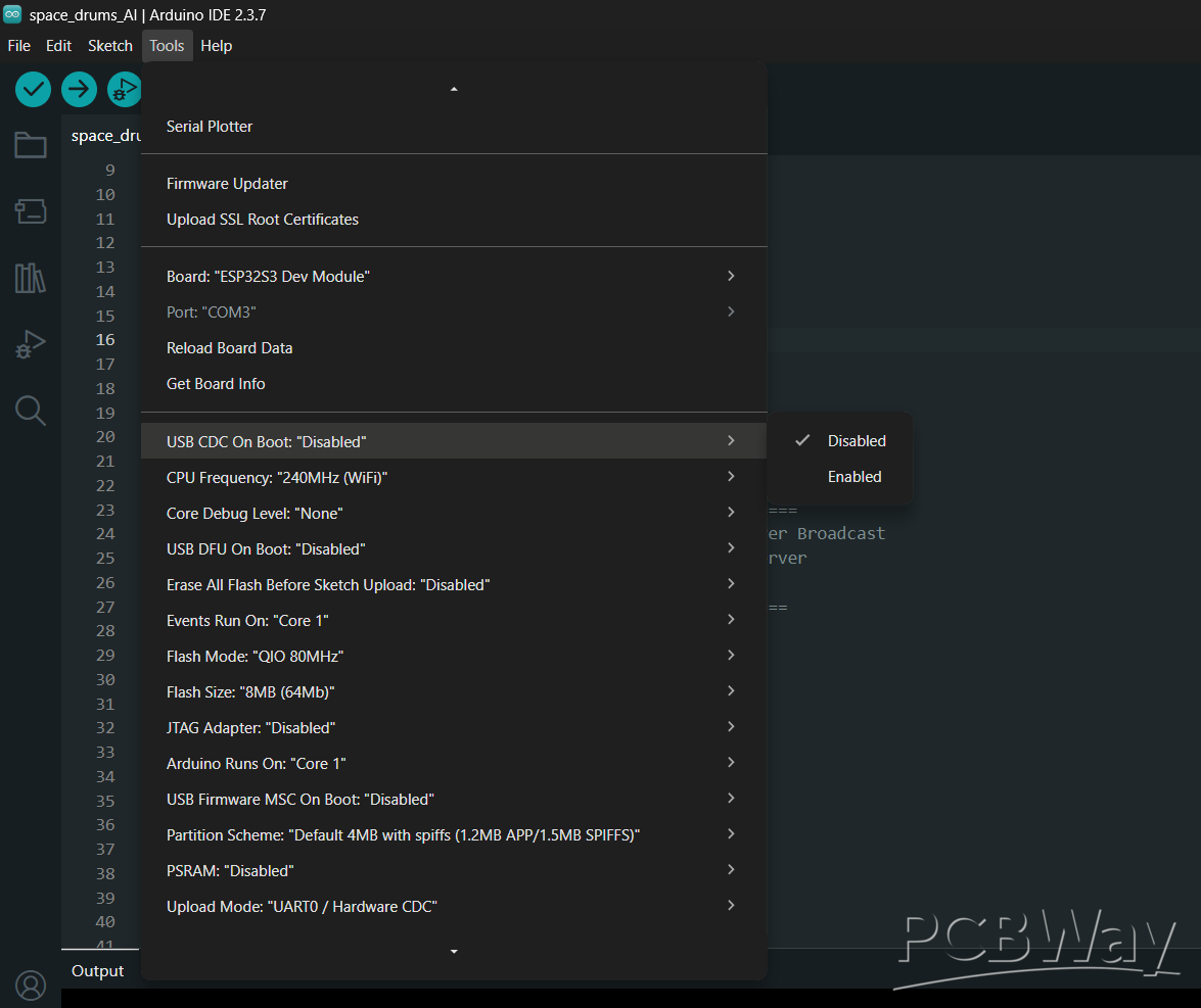
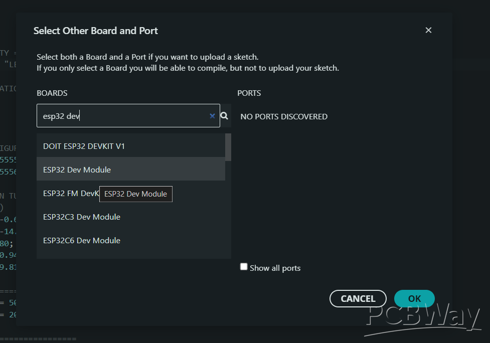
- In the Arduino IDE, set the board target to ESP32S3 Dev Module, disable USB CDC On Boot, and execute the flash compilation.
The verified Gerber files and complete hardware design documents are open-source and accessible via my repository at https://github.com/Arpanmondalz/Space-Drums
Step 3: Resolving Spatial Drift (The R&D Journey)
During development, the core issue with using an isolated IMU became obvious: Gyroscope Drift. Because gyroscopes measure relative rotation rather than absolute spatial positioning, tiny mathematical integration errors build up in the tracking variables over time. Within three minutes of continuous play, the virtual center points drift, forcing you to rotate your body awkwardly just to strike the snare.
Solving this issue required working through several design iterations:
Failed Attempt 1: The Digital Compass (Magnetometer)
I attempted to integrate a digital compass to leverage the Earth’s magnetic field as an absolute positional reference. This failed in practical testing. Indoor environments are packed with localized electromagnetic fields generated by computer towers, structural steel desks, and large copper voice-coils inside audio monitors. These fields distorted the magnetometer data, resulting in chaotic spatial tracking.
Failed Attempt 2: The Infrared (IR) Beacon Anchor
Next, I engineered an active localization rig using an IR transmitter base station positioned on the floor and IR photodiode matrices mounted on the sticks to serve as an optical zero-point.
This method was abandoned due to two critical flaws:
The high-frequency electromagnetic switching of the ESP32’s on-board Wi-Fi radio introduced massive RF interference into the high-gain analog amplification stages of the IR receivers.
Ambient indoor lighting and incandescent bulb harmonics blinded the photodiodes, dropping the signal-to-noise ratio below a stable threshold.
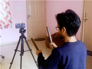
The Solution: The Computer Vision Pivot
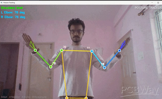
I realized the answer was to offload spatial anchoring entirely to a stationary external device: a smartphone or PC camera. By streaming the camera feed through a python backend powered by Google MediaPipe AI, the server maps out your joints: wrists, elbows, and shoulders, in 3D space. The coordinate system of the drum kit is no longer estimated by the sticks; it is dynamically anchored to your body skeleton. This structural reference frame eliminates spatial drift entirely.
Step 4: Real-Time Physics Engine
While computer vision resolves positional drift, it introduces a major problem: Pipeline Processing Latency. Capturing a frame, compressing it, passing it over the bus, and running inference through a neural network introduces a ~150ms delay. Attempting to play percussion with a 150ms audio lag is completely unusable for timing and rhythm tracking.
To bridge this gap, I developed a predictive spatial-physics engine that splits the data processing responsibilities:

- The Reflex Layer: The moment an IMU registers an acceleration peak exceeding the internal negative G-force threshold, it fires a small UDP trigger packet over network sockets. This takes less than 2ms.
- The Predictive Engine: When the server receives the UDP trigger packet, it doesn't wait for the delayed current camera frame. Instead, it references the historical buffer of the past 50ms of body vectors and uses the terminal angular velocity to project the stick's trajectory forward in time.
- This projection calculates where the stick will land before the visual pipeline finishes processing, matching the impact timestamp with the spatial zone to trigger the audio sample in under 20ms.
Step 5: Firmware Implementation
Open the Arduino IDE and flash your modules using the following configurations:
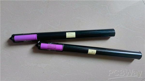
Main Sticks Assembly: Open space_drums_AI.ino. Find the configuration block at the top of the file:
// Configuration Definitions #define WIFI_SSID "SpaceDrums_AP" #define UDP_PORT 5556 #define STICK_ID "Left" // Set to "Left" for primary stick, change to "Right" for secondary stick
Flash your first hardware module with STICK_ID set to "Left". Update the definition to "Right" and flash the second hardware module.
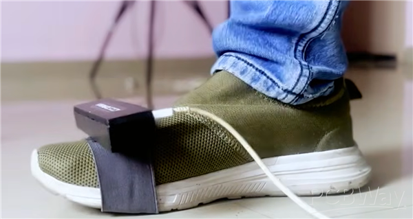
Shoe Module Assembly: Open spaceDrums_kick.ino and flash it onto your third ESP32 module. This firmware isolates the Z-axis linear acceleration vector, monitoring for a sudden downward delta exceeding 1.8 Gs to trigger the bass drum trigger packet.
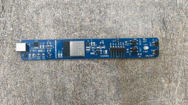
Step 6: Hardware Fabrication
Chassis Preparation: Cut the 1-inch diameter PVC pipe into clean 12-inch lengths. Deburr the edges thoroughly to prevent wire chafing. Apply the wood-grain vinyl wrapper smoothly across the exterior profile using a heat gun to eliminate air pockets.
Power Distribution Rigging: Solder the positive anode of the lithium cell to the input pad of the TP4056 charging board. Route the positive output lead through the mechanical slide switch, terminating at the VIN rail of the custom ESP32 board. Tie all common grounds together.
Mechanical Stabilization: Any internal component movement or loose wiring inside the tube will introduce resonant vibration artifacts. The IMU will interpret these structural vibrations as false hit triggers. Wrap the completed internal core assembly tightly in structural foam tape before sliding it into the PVC cylinder to ensure a rigid press-fit.
Foot Module Construction: Mount the third ESP32 circuit assembly inside a small 3D-printed enclosure. Thread a durable heavy-duty fabric or hook-and-loop strap through the integrated structural slots so it can be strapped firmly over your shoe.
Step 7: Server Orchestration and Calibration
Backend Environment Initialization
For optimum performance, the server should be deployed on a Linux distribution. The Linux ALSA (Advanced Linux Sound Architecture) audio framework provides direct, unbuffered hardware access, keeping sound rendering delays well below the Windows or Android audio layer limitations.
Initialize the host environment using your terminal:
# Clone the core system repository git clone https://github.com/Arpanmondalz/Space-Drums cd Space-Drums # Instantiate dependencies and launch Python stack pip install -r requirements.txt python main.py
Network Pairing
Flick the power switches on the assemblies. On first run, the modules will broadcast local setup networks named AirDrums-Stick and AirDrums-Kick.
Connect a your phone or PC to these access points, fill out your local network credentials via the captive web portal, and commit the settings to the ESP32's non-volatile storage. The hardware will now auto-pair with your local network on subsequent boots.
Run Routine & Spatial Zeroing
The Python initialization terminal will output a local socket address string (e.g., http://192.168.1.13:5000).
Open this address on a camera-equipped device placed directly in front of your play zone. Ensure your upper torso and arms are clearly visible within the frame.
Sensor Calibration: Sit upright, hold both sticks completely steady and parallel directly in front of your chest (pointing toward the intended snare coordinates), and maintain this position for 5 seconds. The firmware averages these readings to establish a clean sensor baseline and subtract static gyro offsets.
Once the skeleton tracking indicators lock onto your joints, the virtual tracking matrices map out your target vectors. You can now play without spatial drift.
Insights & Performance Evaluation
From an engineering perspective, this system does not replicate the tactile feedback of physical acoustic kits, as there is no mechanical rebound of a wooden stick bouncing off a tensioned mylar drumhead.
However, as an exercise in high-speed data filtering, real-time trajectory prediction, and low-cost sensor fusion, it provides a decent latency, space-saving air drumming system.
Space Drums - Open Source Air Drums
*PCBWay community is a sharing platform. We are not responsible for any design issues and parameter issues (board thickness, surface finish, etc.) you choose.


Raspberry Pi 5 7 Inch Touch Screen IPS 1024x600 HD LCD HDMI-compatible Display for RPI 4B 3B+ OPI 5 AIDA64 PC Secondary Screen(Without Speaker)
BUY NOW


- Comments(0)
- Likes(1)
More by Makestreme
-
Programmable Mist Maker - XIAO / QT PY Extension
803 1 0 -
RadioHAT - Raspberry Pi radio development platform
647 0 1 -
-
-
-
-
ARPS-2 – Arduino-Compatible Robot Project Shield for Arduino UNO
3112 0 6 -
A Compact Charging Breakout Board For Waveshare ESP32-C3
3731 3 8 -
AI-driven LoRa & LLM-enabled Kiosk & Food Delivery System
4057 2 2


