


Soft Start Switch module
A Soft Start Circuit Experiment
Every single project that we build needs an On/Off switch. Hardware switches are big and clumsy and can be quite expensive. Most of them also don’t look very good.
This post will be about an experiment that I recently performed, building a reliable soft start circuit, or latching circuit.
Full disclosure: I did not design this circuit. Full credit to the designer, who shall be mentioned later.
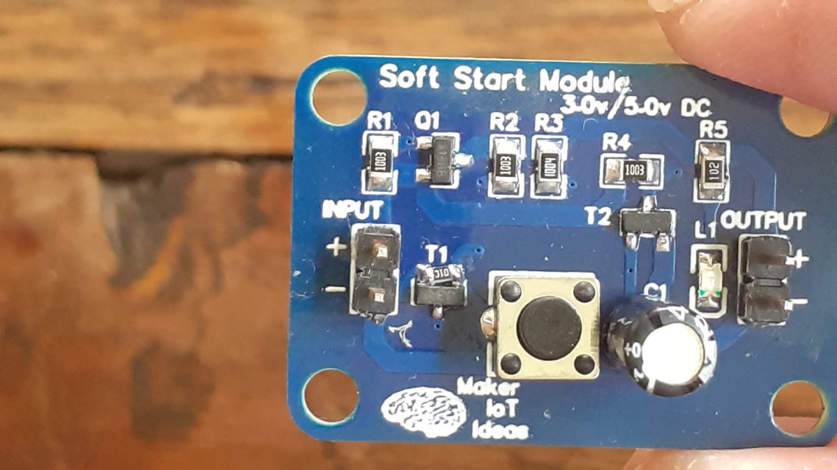
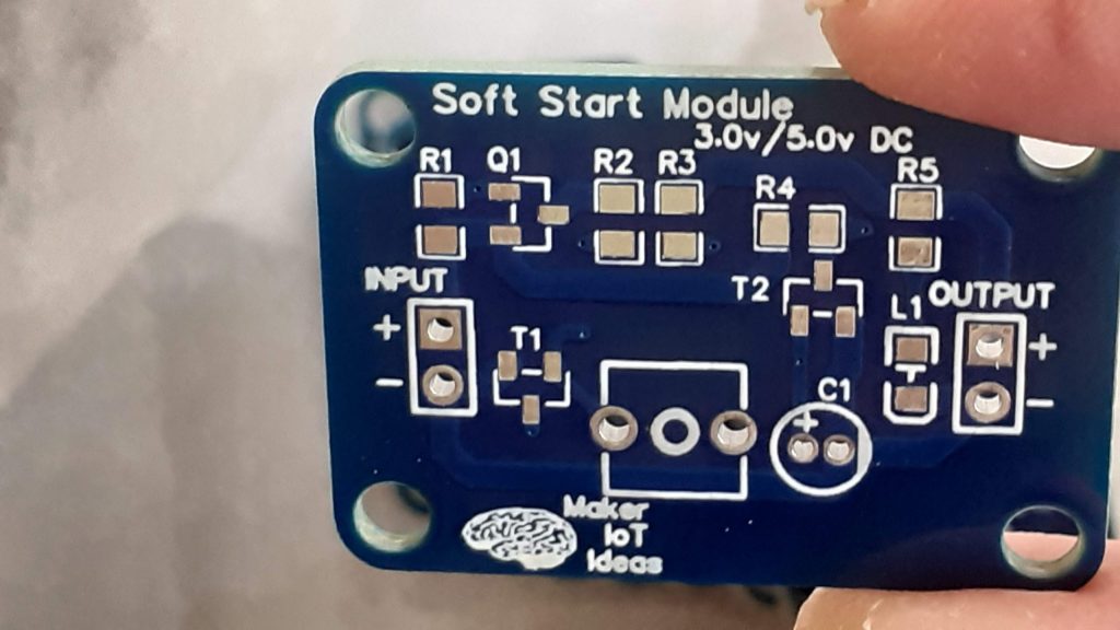
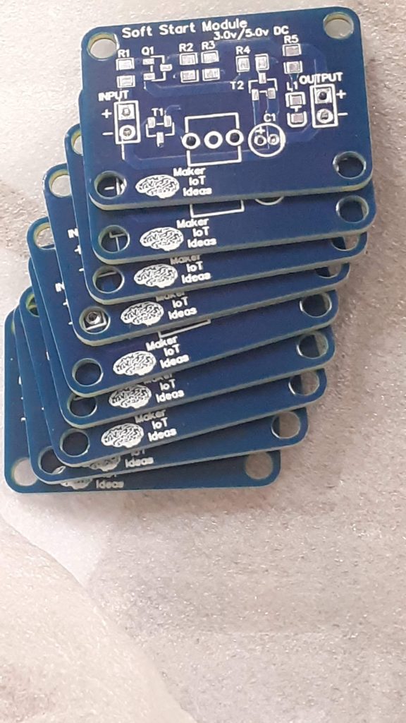
As such, This shall be about my experiences with this great little circuit, and also to show off the neat little prototype PCB that I designed and had manufactured for this experiment. It only took a few minutes to design, and even less to assemble.
The Schematic
 Schematic
How does it work?
To answer this, let us look at what components are in the circuit first.
Q1 is a P-Channel Mosfet. I chose the SI2301, because that is what I had lying around.
T1 and T2 are NPN BJT transistors, I chose S8050’s here, and also tested 2n2222a’s with great success.
Other components are 3 100k pullup resistors, 1 1M pullup and an 1k dropper resistor for the indicator LED.
In the off state, R1 (100k) keeps the gate of Q1 tied to the supply voltage, thus keeping the MOSFET switched off.
T1’s collector, also connected to the MOSFET Gate, are thus pulled High, with the Base of T1, although pulled High, connected to the Drain of Q1.
Q1 is still off, so that base will be low, for now at least.
The collector of T2, is pulled up to the supply voltage via R4, and also, through the push button, to the base of T1.
The base of T2, is pulled up via a 1M resistor to the drain of Q1, and a 22uf to 47uf electrolytic capacitor to ground.
The emitters of both T1 and T2 are grounded.
When you press the switch, the base of T1 goes high, and this switches T1 on, pulling the gate of Q1 to ground, switching it on. This now pulls the base of T1 high through R2, latching it on, and keeping Q1 switched on. This also pulls the base of T2 high through R3. As T2 is now also switched on, the junction between the collector of T2 and the switch is now for all purposes a ground.
Now, when you push the switch again, the base of T1 is pulled down to ground via T2. This switched off Q1. As the capacitor on the base of T2 can now discharge, the circuit is reset, and the next press of the switch will turn it on again.
How big a load can be switched?
Obviously this depends on the rating of the MOSFET at Q1. In my experiments, a load of about 150mA was easily controlled, but more than that, started to somehow drain the cap at C1 too fast, and the circuit would reset.
This is not a problem to me, as the circuit is ideal to switch a relay, which in return can switch the main load.
What other issues did I encounter?
The SI2301 seems to have a small amount of leakage, which allowed a few millivolts to activate T1 or T2. I solved that with the addition of a 10k pulldown to ground, on the base of T1.
This does not seem to be the case with other MOSFETS, and I believe changing the value of R1 to provide a stronger pullup, might solve this issue.
Where does the circuit come from?
I found the circuit, and explanation on the excellent Youtube channel EEVBlog.
The owner, Dave, does an excellent job of explaining how this works. All credit to Dave for this excellent circuit!
It has zero current consumption in the off-state, and very little when on.
Conclusion
I believe this is a great little circuit to keep around, with many excellent use scenarios. It does need a bit of fiddling to get to work perfectly every time ( as you can use many different P Channel Mosfets and NPN BJT transistors)
It provides an excellent alternative to a mechanical switch, and for my own use, the PCB Module is small enough to be mounted into an enclosure with another project with ease.

Soft Start Switch module
Project images are for reference only. Actual production is based on the manufacturing files on the project page.
Please review the designer's notes (e.g., PCB thickness) and select the appropriate options.
PCBWay is not responsible
for issues caused by unsuitable parameter selections.
For more important ordering information, please refer to
Read More


Raspberry Pi 5 7 Inch Touch Screen IPS 1024x600 HD LCD HDMI-compatible Display for RPI 4B 3B+ OPI 5 AIDA64 PC Secondary Screen(Without Speaker)
BUY NOW


- Comments(0)
- Likes(1)
More by Jean Redelinghuys MakerIoT2020
-
 PCB_MCP23008_2023-10-08
MCP23008 BreakoutI designed this breakout to assist me during prototyping my next version of the “RP...
PCB_MCP23008_2023-10-08
MCP23008 BreakoutI designed this breakout to assist me during prototyping my next version of the “RP...
-
 PCB_XiaoRP2040-Mouse-REV2
Xiao RP2040 Joystick Mouse – revision 2.00Revision 1.0 of the ProjectOver the last few months, I hav...
PCB_XiaoRP2040-Mouse-REV2
Xiao RP2040 Joystick Mouse – revision 2.00Revision 1.0 of the ProjectOver the last few months, I hav...
-
 Multi Purpose IO Card
Multi-Purpose IO CardWhen we are working on a prototype, we always need access to pushbuttons, encod...
Multi Purpose IO Card
Multi-Purpose IO CardWhen we are working on a prototype, we always need access to pushbuttons, encod...
-
 Variable Voltage Power Module
Powering electronics projects are always challenging. This Variable vol...
Variable Voltage Power Module
Variable Voltage Power ModulePowering electronics projects are always challenging. This Variable vol...
-
 I2C Matrix Keypad
An I2C Matrix KeypadThe completed I2C Matrix KeypadIn a previous post this month I introduced my 4×4...
I2C Matrix Keypad
An I2C Matrix KeypadThe completed I2C Matrix KeypadIn a previous post this month I introduced my 4×4...
-
 ESP32-S Development Board, in "Arduino Uno" form factor
UPDATE 24/06/2023:This board now has a Hardware Revision 2.0 available. It is the same board but wit...
ESP32-S Development Board, in "Arduino Uno" form factor
UPDATE 24/06/2023:This board now has a Hardware Revision 2.0 available. It is the same board but wit...
-
 W307186ASC94_Gerber_PCB_USB-Ports
USB Power Supply ModuleUSB Ports are quite handy to power all our day-to-day electronic devices, but...
W307186ASC94_Gerber_PCB_USB-Ports
USB Power Supply ModuleUSB Ports are quite handy to power all our day-to-day electronic devices, but...
-
 Atmega 328P based PWM controller Card
ATMega 328P Based PWM controller CardAs part of my recent ESP-12E I2C Base Board project, I designed...
Atmega 328P based PWM controller Card
ATMega 328P Based PWM controller CardAs part of my recent ESP-12E I2C Base Board project, I designed...
-
 W307186ASC71_Gerber_PCB_ESP-Now Remote
Today we will look at the remote control unit for the Robotic Toy Car – Part 6.The project is close ...
W307186ASC71_Gerber_PCB_ESP-Now Remote
Today we will look at the remote control unit for the Robotic Toy Car – Part 6.The project is close ...
-
 W307186ASV69_Gerber_PCB_Robot-Car-MCU-Board Prototype
In our last project, we started working on repurposing an old toy car. In this part, Robot Toy Car –...
W307186ASV69_Gerber_PCB_Robot-Car-MCU-Board Prototype
In our last project, we started working on repurposing an old toy car. In this part, Robot Toy Car –...
-
 W307186ASV62_Gerber_PCB_DUAL-H-Bridge
by makeriot2020 on May 27, 2022Many of us have old toys laying around the house, they belong to ou...
W307186ASV62_Gerber_PCB_DUAL-H-Bridge
by makeriot2020 on May 27, 2022Many of us have old toys laying around the house, they belong to ou...
-
 CAN-BUS Breakout
Breadboard Compatible CAN-BUS Breakout ModuleWhat is this:Some of us have already used the commonly ...
CAN-BUS Breakout
Breadboard Compatible CAN-BUS Breakout ModuleWhat is this:Some of us have already used the commonly ...
-
 RA-02 Breakout with Level converters
Breadboard and beginner-friendly RA-02 Breakout ModuleMost Makers and electronics enthusiasts may al...
RA-02 Breakout with Level converters
Breadboard and beginner-friendly RA-02 Breakout ModuleMost Makers and electronics enthusiasts may al...
-
 ATMEGA328P Module with integrated LoRa and CAN Bus
ATMEGA328P Module with integrated LoRa and CAN-BUSINTRODUCTIONIn my quest to perfect my LoRa telemet...
ATMEGA328P Module with integrated LoRa and CAN Bus
ATMEGA328P Module with integrated LoRa and CAN-BUSINTRODUCTIONIn my quest to perfect my LoRa telemet...
-
 Sx127x-Ra-02-Test-Module with ATMEGA328P-AU
SX127x LoRa/FSK/OOK Prototype Radio BoardI recently had a requirement to do some automation/telemetr...
Sx127x-Ra-02-Test-Module with ATMEGA328P-AU
SX127x LoRa/FSK/OOK Prototype Radio BoardI recently had a requirement to do some automation/telemetr...
-
 USB-ASP Programmer ATMEGA8
Build your own USB-ASP Programmer CloneBymakeriot2020 FEB 21, 2022 Arduino, ASP programmerUsing mor...
USB-ASP Programmer ATMEGA8
Build your own USB-ASP Programmer CloneBymakeriot2020 FEB 21, 2022 Arduino, ASP programmerUsing mor...
-
 ATTiny1616-LIGHT-Controller-with-CAN_B_PCB_ATTiny1616-LIGHT-Controller-with-C_2024-09-11
Assembly of the ATTiny1616 Can bus controller PCBThe Assembly of the ATTiny1616 Can Bus Controller P...
ATTiny1616-LIGHT-Controller-with-CAN_B_PCB_ATTiny1616-LIGHT-Controller-with-C_2024-09-11
Assembly of the ATTiny1616 Can bus controller PCBThe Assembly of the ATTiny1616 Can Bus Controller P...
-
 ATTiny1616QFN-CAN-Remote-Neopixel-Ligh_PCB_ATTiny1616QFN-CAN-Remote-Neopixel-2024-09-11_2024-09-11
NeoPixel CAN-Bus Module with local controlAs part of my current project to add NeoPixels to the cabi...
ATTiny1616QFN-CAN-Remote-Neopixel-Ligh_PCB_ATTiny1616QFN-CAN-Remote-Neopixel-2024-09-11_2024-09-11
NeoPixel CAN-Bus Module with local controlAs part of my current project to add NeoPixels to the cabi...
-
Programmable Mist Maker - XIAO / QT PY Extension
1108 2 1 -
RadioHAT - Raspberry Pi radio development platform
917 0 2 -
-
-
-
-
ARPS-2 – Arduino-Compatible Robot Project Shield for Arduino UNO
3352 0 6 -
A Compact Charging Breakout Board For Waveshare ESP32-C3
3965 3 8 -
AI-driven LoRa & LLM-enabled Kiosk & Food Delivery System
4354 2 2


