


|
|
EasyEDA |
|

|
arduino IDEArduino
|
W307186ASV69_Gerber_PCB_Robot-Car-MCU-Board Prototype
In our last project, we started working on repurposing an old toy car. In this part, Robot Toy Car – The next steps, we will take a look at the controller board for this project and discuss some of the problems that we have encountered up to now. Most of the various components for this project are still in the prototype stage, but It is quite important to get them tested to verify the final designs.
There are quite a few unique challenges in a project like this, which looks quite easy to solve but turn out to become quite challenging to get working just right in practice…
One of the most important, as well as the most frustrating part, turned out to be the H-Bridge Motor controller. The first prototype of this was introduced in the first part of this project. While functional on paper, as well as working quite well in real life, (when tested with an Arduino, as well as manually), It performs extremely poorly when used with the actual controller for this project, an ESP8266 12-E…
What could the reason be? How will I fix it…? The answers to that will be provided in a follow-up post. For now, let us take a look at the controller.
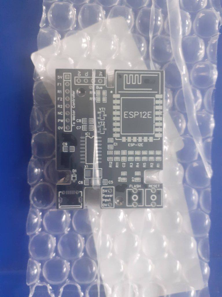 The unassembled ESP-8266 Controller board, straight from the factory
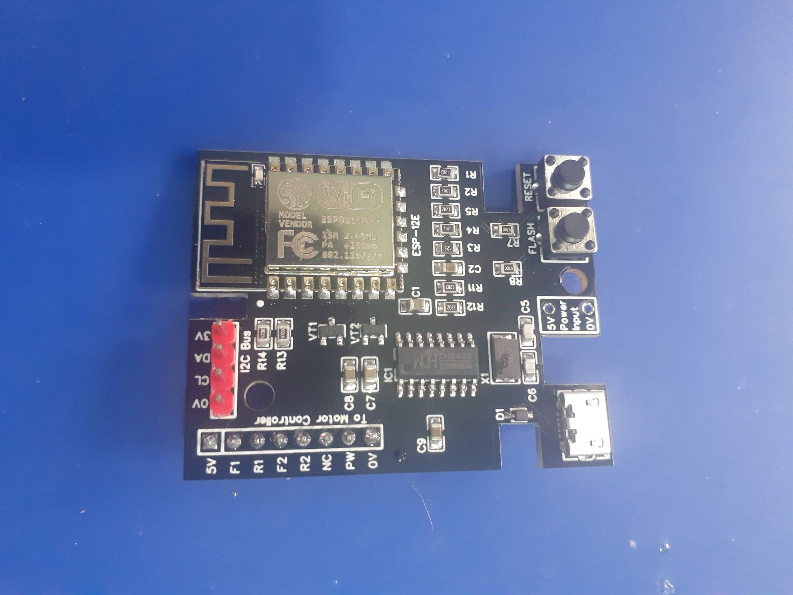
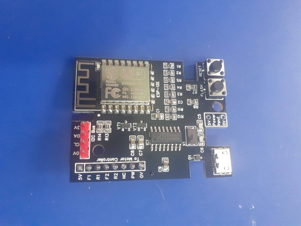 The Assembled ESP-8266 Controller board.
The Controller Board, details
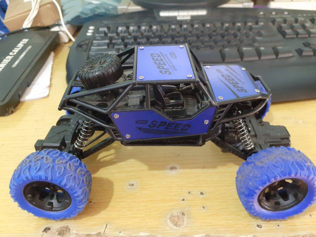
Space inside the toy car is at a premium, so from the start, it was important to design a PCB that was small enough to fit, while also taking into consideration functionality, as well as all additional add-on components to ultimately be fitted to the project.
With this in mind, I have decided on the ESP-8266, which, while bigger than an Atmega328, does offer a few additional features, like WiFi, and ESP-Now, which will greatly help in controlling and even updating firmware OTA. The ESP-8266 does however also have a few serious flaws in this design, like limited useable GPIO pins, a 3.3v working voltage requirement, and quite high operating current requirements.
As the toy will likely not be used continuously, as well as the fact that it will run on batteries, which, can be replaced or recharged, I did not worry too much about the power issue. As far as the limited GPIO, that is where I2C comes in… It is quite easy to expand the GPIO with an IO Expander or two…
My main problem came in the form of the CH340G USB-to-UART converter chip. It seems like there must be quite a lot of counterfeit versions of these around, as none of the chips that I purchased, from many different suppliers, actually functioned, with the best one actually providing a USB port, but, when investigating with a logic analyser, the Rx and Tx lines of the UART, generating garbage…
Replacing it with a known working chip from a NodeMCU V1 board, magically solved the problem, verifying the PCB circuit as correct and working, and also proving that the purchased chips are definitely fake!
This was easily repaired by temporarily soldering jumper cables to the Rx and Tx lines on the ESP-8266, and using an external UART-to-USB converter to upload the initial sketch to the device. Future updates will be OTA, so not a problem in the long run anyway.
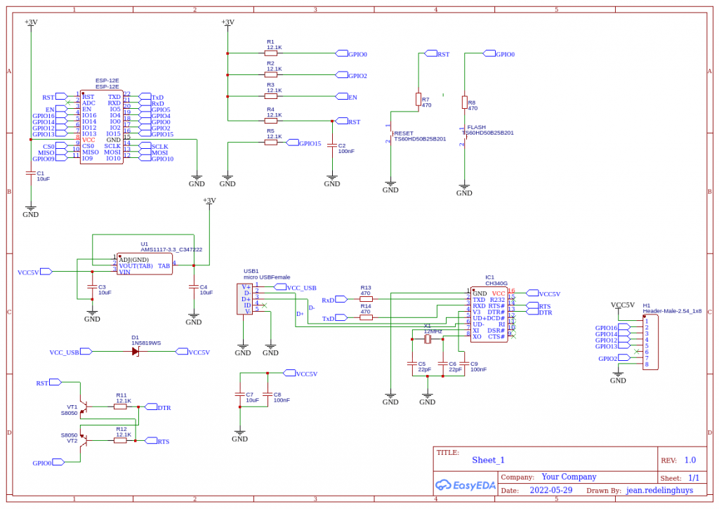 Controller Schematic
The controller schematic, above, is basically a rearranged stock NodeMCU v1 circuit, with the only difference being that only specific pins were broken out onto header pins. These will be used for controlling the two H-Bridges, and provide PWM as well as access to the I2C bus.
Software
Due to the fact that this controller is still definitely considered a prototype, my main focus is definitely on getting the control software sorted out first. That way, at least in my opinion, I can then focus on hardware issues responding to verified software inputs, without having to do both at the same time.
As mentioned before, I require OTA capability to upload new firmware to the device, so my starting point was the BasicOTA sketch provided with the Arduino IDE. This sketch was modified to perform some additional functionality, such as controlling the H-Bridges, PWM as well as a roof-mounted “status panel” with LED’s that also doubles as a visual display, to give a bit of colour to the project.
The “status panel” will be shown in a future post, however, with the only mention of it here being that it is I2C controlled, and based on a PCF8574.
The BasicOTA sketch is listed below.
#include <ESP8266WiFi.h>
#include <ESP8266mDNS.h>
#include <WiFiUdp.h>
#include <ArduinoOTA.h>

#ifndef STASSID
#define STASSID "your-ssid"
#define STAPSK  "your-password"
#endif

const char* ssid = STASSID;
const char* password = STAPSK;

void setup() {
  Serial.begin(115200);
  Serial.println("Booting");
  WiFi.mode(WIFI_STA);
  WiFi.begin(ssid, password);
  while (WiFi.waitForConnectResult() != WL_CONNECTED) {
    Serial.println("Connection Failed! Rebooting...");
    delay(5000);
    ESP.restart();
  }

  // Port defaults to 8266
  // ArduinoOTA.setPort(8266);

  // Hostname defaults to esp8266-[ChipID]
  // ArduinoOTA.setHostname("myesp8266");

  // No authentication by default
  // ArduinoOTA.setPassword("admin");

  // Password can be set with it's md5 value as well
  // MD5(admin) = 21232f297a57a5a743894a0e4a801fc3
  // ArduinoOTA.setPasswordHash("21232f297a57a5a743894a0e4a801fc3");

  ArduinoOTA.onStart([]() {
    String type;
    if (ArduinoOTA.getCommand() == U_FLASH) {
      type = "sketch";
    } else { // U_FS
      type = "filesystem";
    }

    // NOTE: if updating FS this would be the place to unmount FS using FS.end()
    Serial.println("Start updating " + type);
  });
  ArduinoOTA.onEnd([]() {
    Serial.println("\nEnd");
  });
  ArduinoOTA.onProgress([](unsigned int progress, unsigned int total) {
    Serial.printf("Progress: %u%%\r", (progress / (total / 100)));
  });
  ArduinoOTA.onError([](ota_error_t error) {
    Serial.printf("Error[%u]: ", error);
    if (error == OTA_AUTH_ERROR) {
      Serial.println("Auth Failed");
    } else if (error == OTA_BEGIN_ERROR) {
      Serial.println("Begin Failed");
    } else if (error == OTA_CONNECT_ERROR) {
      Serial.println("Connect Failed");
    } else if (error == OTA_RECEIVE_ERROR) {
      Serial.println("Receive Failed");
    } else if (error == OTA_END_ERROR) {
      Serial.println("End Failed");
    }
  });
  ArduinoOTA.begin();
  Serial.println("Ready");
  Serial.print("IP address: ");
  Serial.println(WiFi.localIP());
}

void loop() {
  ArduinoOTA.handle();
}
Controlling the Toy Car Robot
Controlling the Toy Car is a complicated question, with many ideas jumping into my mind, only to be pushed aside by technical issues, as well as real-world constraints on what is physically possible to be mounted on the plastic body of the toy car, space available on the inside, as well as not interfering with suspensions, springs, turning wheels etc.
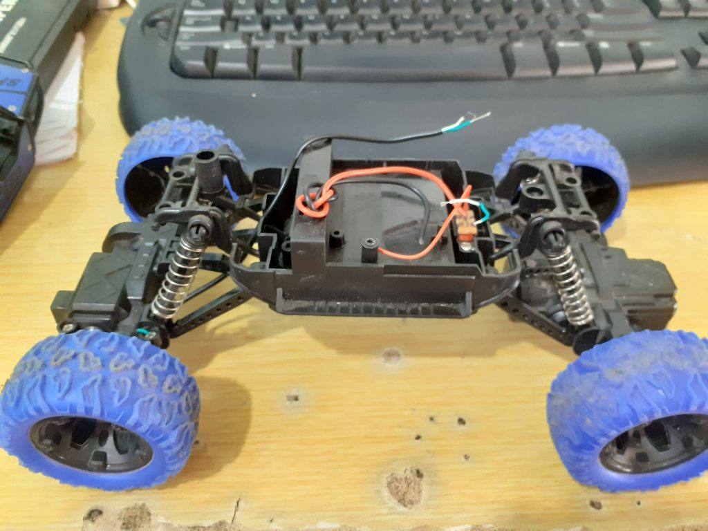 The chassis of the toy car
As is clearly visible, there is really not a lot of space available here for sensors. Mounting sensors to the body will also provide a bit of a challenge, as well as won’t really look nice either…
I have thus decided to implement remote control for the time being, and later, maybe after 3d-printing a more suitable body, to add sensors for autonomous functionality. The ESP-Now protocol will be used extensively for the remote control, as, in my opinion, it required no additional hardware, is quite fast, as well as being extremely easy to use. It does however make it necessary to use another ESP deice in the remote control unit.
#include <ESP8266WiFi.h>
#include <ESP8266mDNS.h>
#include <WiFiUdp.h>
#include <ArduinoOTA.h>
#ifndef STASSID
#define STASSID "your-ssid"
#define STAPSK "your-password"
#endif
const char* ssid = STASSID;
const char* password = STAPSK;
void setup() {
Serial.begin(115200);
Serial.println("Booting");
WiFi.mode(WIFI_STA);
WiFi.begin(ssid, password);
while (WiFi.waitForConnectResult() != WL_CONNECTED) {
Serial.println("Connection Failed! Rebooting...");
delay(5000);
ESP.restart();
}
// Port defaults to 8266
// ArduinoOTA.setPort(8266);
// Hostname defaults to esp8266-[ChipID]
// ArduinoOTA.setHostname("myesp8266");
// No authentication by default
// ArduinoOTA.setPassword("admin");
// Password can be set with it's md5 value as well
// MD5(admin) = 21232f297a57a5a743894a0e4a801fc3
// ArduinoOTA.setPasswordHash("21232f297a57a5a743894a0e4a801fc3");
ArduinoOTA.onStart([]() {
String type;
if (ArduinoOTA.getCommand() == U_FLASH) {
type = "sketch";
} else { // U_FS
type = "filesystem";
}
// NOTE: if updating FS this would be the place to unmount FS using FS.end()
Serial.println("Start updating " + type);
});
ArduinoOTA.onEnd([]() {
Serial.println("\nEnd");
});
ArduinoOTA.onProgress([](unsigned int progress, unsigned int total) {
Serial.printf("Progress: %u%%\r", (progress / (total / 100)));
});
ArduinoOTA.onError([](ota_error_t error) {
Serial.printf("Error[%u]: ", error);
if (error == OTA_AUTH_ERROR) {
Serial.println("Auth Failed");
} else if (error == OTA_BEGIN_ERROR) {
Serial.println("Begin Failed");
} else if (error == OTA_CONNECT_ERROR) {
Serial.println("Connect Failed");
} else if (error == OTA_RECEIVE_ERROR) {
Serial.println("Receive Failed");
} else if (error == OTA_END_ERROR) {
Serial.println("End Failed");
}
});
ArduinoOTA.begin();
Serial.println("Ready");
Serial.print("IP address: ");
Serial.println(WiFi.localIP());
}
void loop() {
ArduinoOTA.handle();
}

W307186ASV69_Gerber_PCB_Robot-Car-MCU-Board Prototype
*PCBWay community is a sharing platform. We are not responsible for any design issues and parameter issues (board thickness, surface finish, etc.) you choose.


Raspberry Pi 5 7 Inch Touch Screen IPS 1024x600 HD LCD HDMI-compatible Display for RPI 4B 3B+ OPI 5 AIDA64 PC Secondary Screen(Without Speaker)
BUY NOW


- Comments(0)
- Likes(1)
More by Jean Redelinghuys MakerIoT2020
-
 PCB_MCP23008_2023-10-08
MCP23008 BreakoutI designed this breakout to assist me during prototyping my next version of the “RP...
PCB_MCP23008_2023-10-08
MCP23008 BreakoutI designed this breakout to assist me during prototyping my next version of the “RP...
-
 PCB_XiaoRP2040-Mouse-REV2
Xiao RP2040 Joystick Mouse – revision 2.00Revision 1.0 of the ProjectOver the last few months, I hav...
PCB_XiaoRP2040-Mouse-REV2
Xiao RP2040 Joystick Mouse – revision 2.00Revision 1.0 of the ProjectOver the last few months, I hav...
-
 Multi Purpose IO Card
Multi-Purpose IO CardWhen we are working on a prototype, we always need access to pushbuttons, encod...
Multi Purpose IO Card
Multi-Purpose IO CardWhen we are working on a prototype, we always need access to pushbuttons, encod...
-
 Variable Voltage Power Module
Powering electronics projects are always challenging. This Variable vol...
Variable Voltage Power Module
Variable Voltage Power ModulePowering electronics projects are always challenging. This Variable vol...
-
 I2C Matrix Keypad
An I2C Matrix KeypadThe completed I2C Matrix KeypadIn a previous post this month I introduced my 4×4...
I2C Matrix Keypad
An I2C Matrix KeypadThe completed I2C Matrix KeypadIn a previous post this month I introduced my 4×4...
-
 ESP32-S Development Board, in "Arduino Uno" form factor
UPDATE 24/06/2023:This board now has a Hardware Revision 2.0 available. It is the same board but wit...
ESP32-S Development Board, in "Arduino Uno" form factor
UPDATE 24/06/2023:This board now has a Hardware Revision 2.0 available. It is the same board but wit...
-
 W307186ASC94_Gerber_PCB_USB-Ports
USB Power Supply ModuleUSB Ports are quite handy to power all our day-to-day electronic devices, but...
W307186ASC94_Gerber_PCB_USB-Ports
USB Power Supply ModuleUSB Ports are quite handy to power all our day-to-day electronic devices, but...
-
 Atmega 328P based PWM controller Card
ATMega 328P Based PWM controller CardAs part of my recent ESP-12E I2C Base Board project, I designed...
Atmega 328P based PWM controller Card
ATMega 328P Based PWM controller CardAs part of my recent ESP-12E I2C Base Board project, I designed...
-
 W307186ASC71_Gerber_PCB_ESP-Now Remote
Today we will look at the remote control unit for the Robotic Toy Car – Part 6.The project is close ...
W307186ASC71_Gerber_PCB_ESP-Now Remote
Today we will look at the remote control unit for the Robotic Toy Car – Part 6.The project is close ...
-
 W307186ASV69_Gerber_PCB_Robot-Car-MCU-Board Prototype
In our last project, we started working on repurposing an old toy car. In this part, Robot Toy Car –...
W307186ASV69_Gerber_PCB_Robot-Car-MCU-Board Prototype
In our last project, we started working on repurposing an old toy car. In this part, Robot Toy Car –...
-
 W307186ASV62_Gerber_PCB_DUAL-H-Bridge
by makeriot2020 on May 27, 2022Many of us have old toys laying around the house, they belong to ou...
W307186ASV62_Gerber_PCB_DUAL-H-Bridge
by makeriot2020 on May 27, 2022Many of us have old toys laying around the house, they belong to ou...
-
 CAN-BUS Breakout
Breadboard Compatible CAN-BUS Breakout ModuleWhat is this:Some of us have already used the commonly ...
CAN-BUS Breakout
Breadboard Compatible CAN-BUS Breakout ModuleWhat is this:Some of us have already used the commonly ...
-
 RA-02 Breakout with Level converters
Breadboard and beginner-friendly RA-02 Breakout ModuleMost Makers and electronics enthusiasts may al...
RA-02 Breakout with Level converters
Breadboard and beginner-friendly RA-02 Breakout ModuleMost Makers and electronics enthusiasts may al...
-
 ATMEGA328P Module with integrated LoRa and CAN Bus
ATMEGA328P Module with integrated LoRa and CAN-BUSINTRODUCTIONIn my quest to perfect my LoRa telemet...
ATMEGA328P Module with integrated LoRa and CAN Bus
ATMEGA328P Module with integrated LoRa and CAN-BUSINTRODUCTIONIn my quest to perfect my LoRa telemet...
-
 Sx127x-Ra-02-Test-Module with ATMEGA328P-AU
SX127x LoRa/FSK/OOK Prototype Radio BoardI recently had a requirement to do some automation/telemetr...
Sx127x-Ra-02-Test-Module with ATMEGA328P-AU
SX127x LoRa/FSK/OOK Prototype Radio BoardI recently had a requirement to do some automation/telemetr...
-
 USB-ASP Programmer ATMEGA8
Build your own USB-ASP Programmer CloneBymakeriot2020 FEB 21, 2022 Arduino, ASP programmerUsing mor...
USB-ASP Programmer ATMEGA8
Build your own USB-ASP Programmer CloneBymakeriot2020 FEB 21, 2022 Arduino, ASP programmerUsing mor...
-
 ATTiny1616-LIGHT-Controller-with-CAN_B_PCB_ATTiny1616-LIGHT-Controller-with-C_2024-09-11
Assembly of the ATTiny1616 Can bus controller PCBThe Assembly of the ATTiny1616 Can Bus Controller P...
ATTiny1616-LIGHT-Controller-with-CAN_B_PCB_ATTiny1616-LIGHT-Controller-with-C_2024-09-11
Assembly of the ATTiny1616 Can bus controller PCBThe Assembly of the ATTiny1616 Can Bus Controller P...
-
 ATTiny1616QFN-CAN-Remote-Neopixel-Ligh_PCB_ATTiny1616QFN-CAN-Remote-Neopixel-2024-09-11_2024-09-11
NeoPixel CAN-Bus Module with local controlAs part of my current project to add NeoPixels to the cabi...
ATTiny1616QFN-CAN-Remote-Neopixel-Ligh_PCB_ATTiny1616QFN-CAN-Remote-Neopixel-2024-09-11_2024-09-11
NeoPixel CAN-Bus Module with local controlAs part of my current project to add NeoPixels to the cabi...
-
-
ARPS-2 – Arduino-Compatible Robot Project Shield for Arduino UNO
1304 0 4 -
A Compact Charging Breakout Board For Waveshare ESP32-C3
1825 3 7 -
AI-driven LoRa & LLM-enabled Kiosk & Food Delivery System
1813 2 0 -
-
-
-
ESP32-C3 BLE Keyboard - Battery Powered with USB-C Charging
1990 0 1 -


