


ESP32-S Development Board, in "Arduino Uno" form factor
UPDATE 24/06/2023:
This board now has a Hardware Revision 2.0 available. It is the same board but with additional components, namely a DC barrel connector, as well as an auto reset/flash circuit - on a 6-way programming header... Routing has been optimised, to provide better temperature control on the main ESP32 Chip.
See more details >> HERE <<
ESP32-S in Arduino Form Factor
The ESP32-S is, at least in my opinion, one of the most versatile microcontrollers available to the Maker at this moment. It ticks almost all of my boxes for features required in a microcontroller, with a lot of gpio’s, WiFi, and Bluetooth, as well as a lot of storage space for code.
I do however have an issue with it, which I usually get around by designing a custom circuit board with a specific purpose. This is great for a project, but as most projects do not start on a custom-built circuit board, I am usually required to use a breadboard module. This is where my problems start. These modules are cumbersome to fit on a breadboard, to say the least, taking up a lot of space, and leaving very little space to connect to its pins with anything else.
Some of these modules do not even fit on the breadboard, making it necessary to hang one side off the breadboard or use two breadboards with a gap in the middle. I am quite sure many people can relate to this problem.
My second issue is that when you have done your breadboarding, and want to go to a permanent project, which does not always need a dedicated PCB, you are now required to either live with things on a breadboard, scary to say the least or have a “spider” with many modules and wires, in a box or partly on protoboard etc…
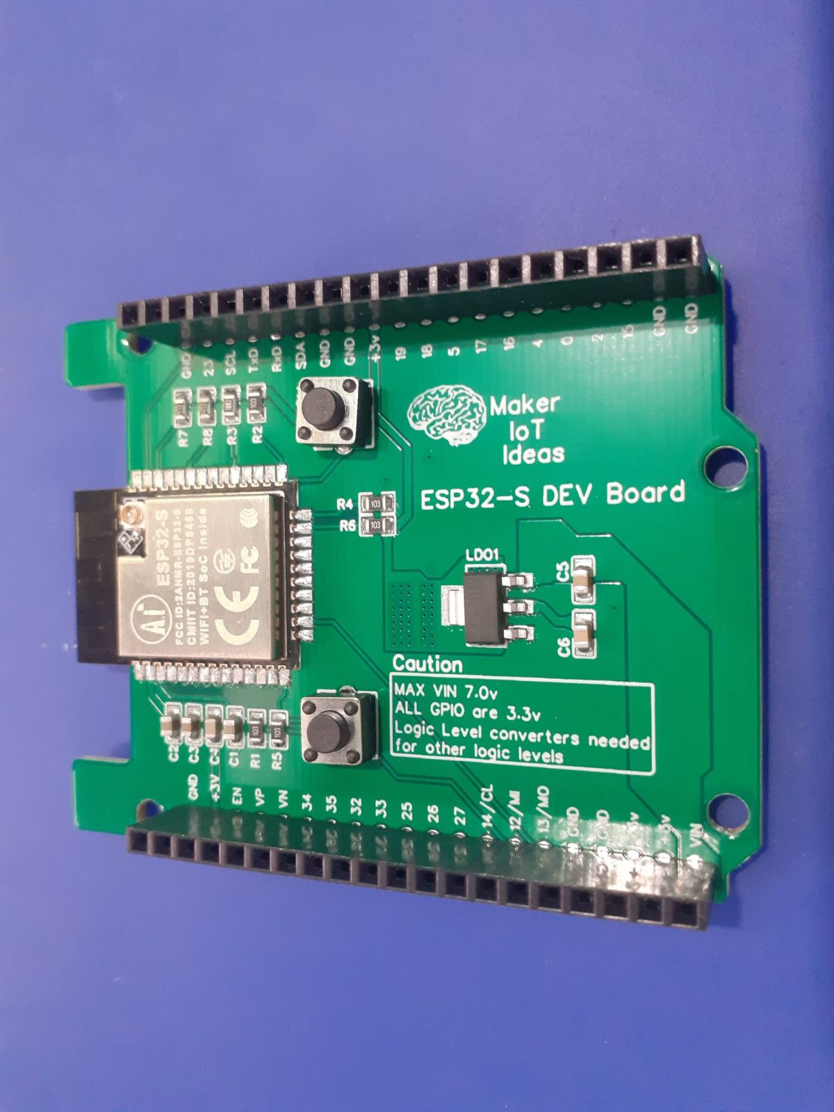
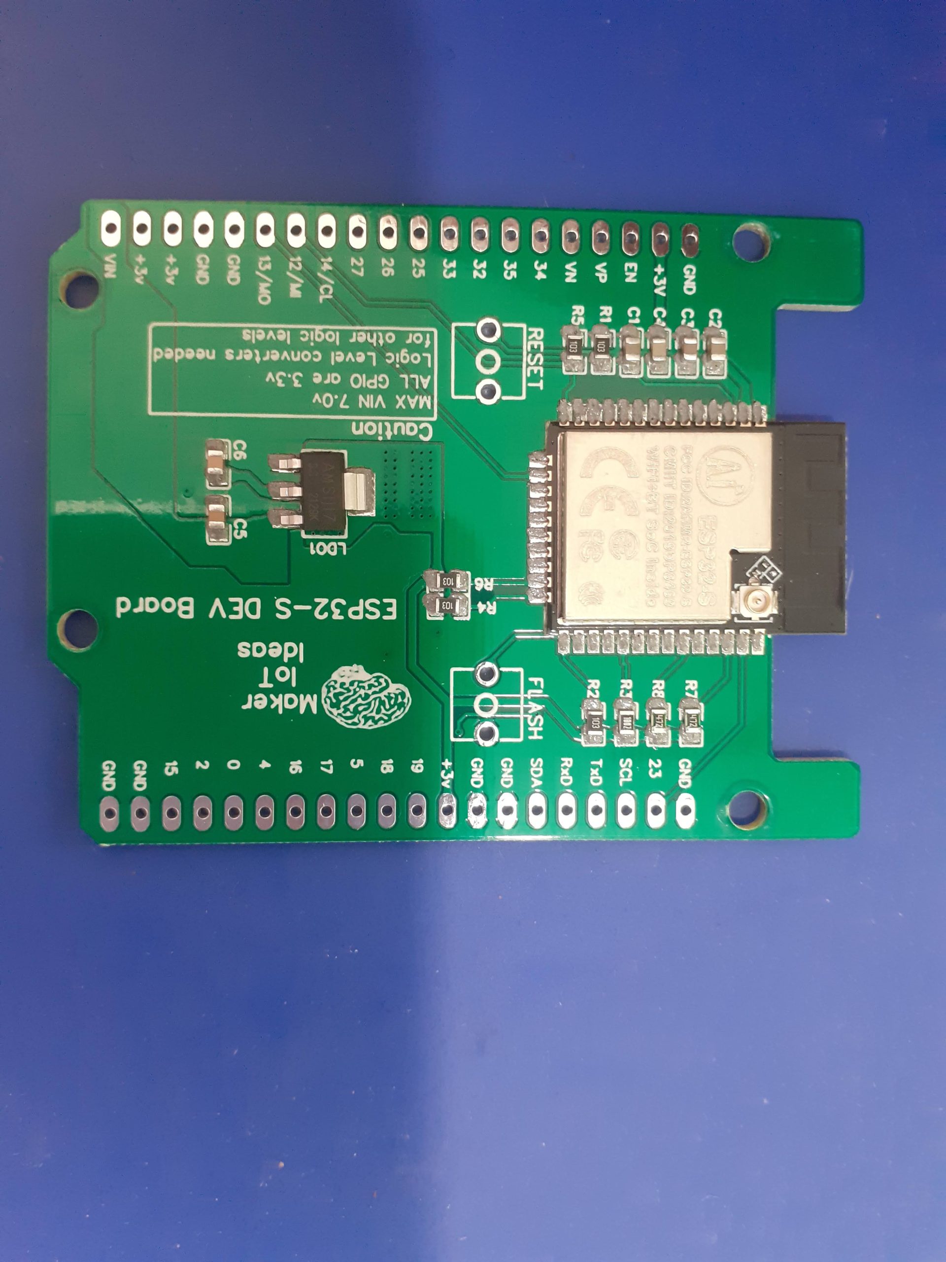
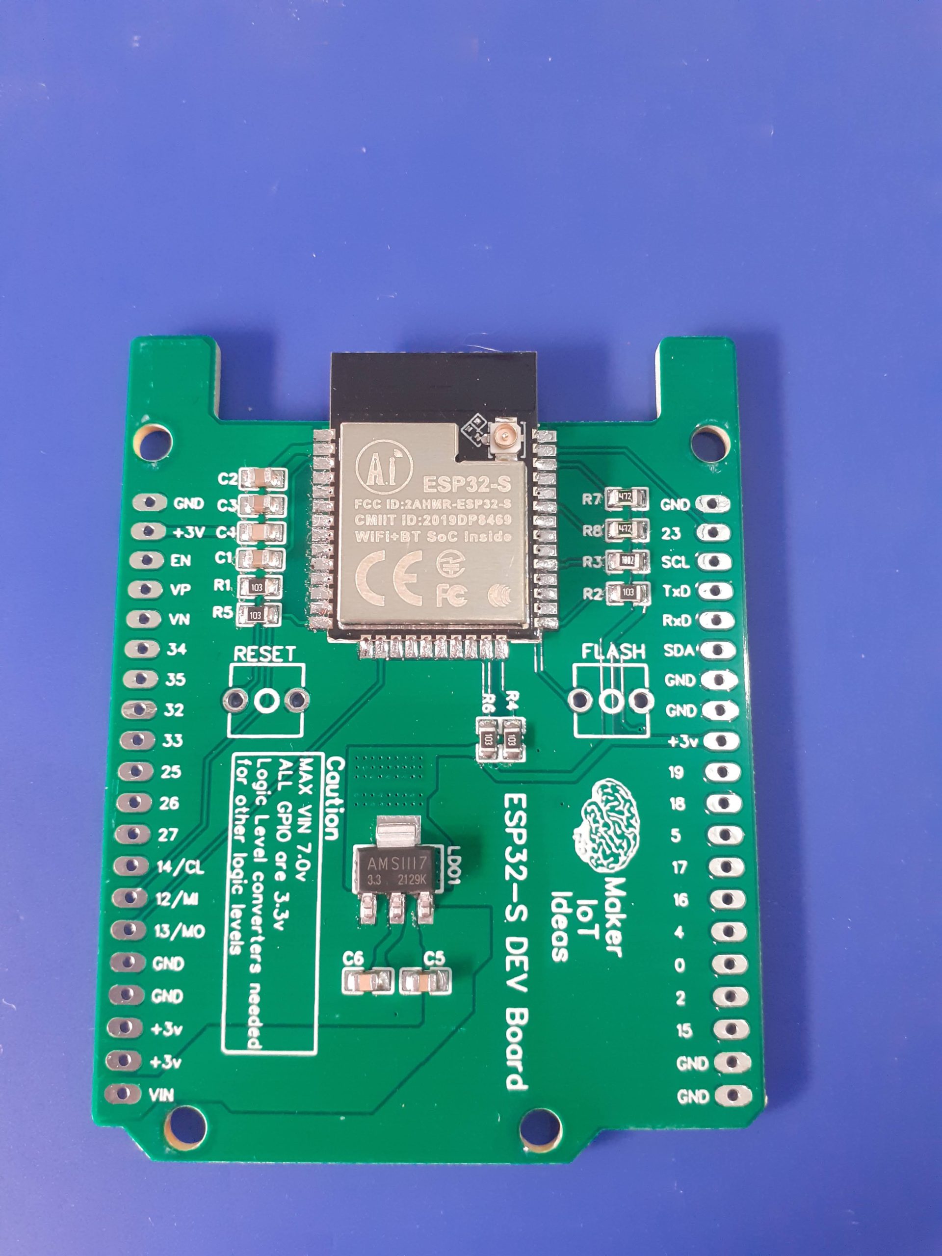
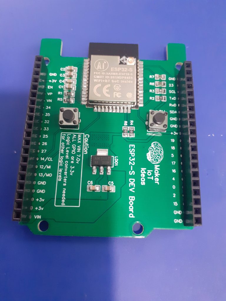 My Solution, the ESP32-S DEV Board, in Arduino Uno form factor
My solution
While not the most elegant, personally I really like the size, and layout of the humble Arduino Uno, with its standardised pinouts, and a large number of addon shields available for the platform. This made me think, sure, there are already ESP32-based boards in this form factor available commercially, but why not make my own instead, as well as a few of my most used modules in a standardised shield form, to make my life just that little bit easier?
The picture above shows my attempt, with most of the GPIO broken out onto female header pins (except for the 6 gpio that are connected to the internal flash chip on the module).
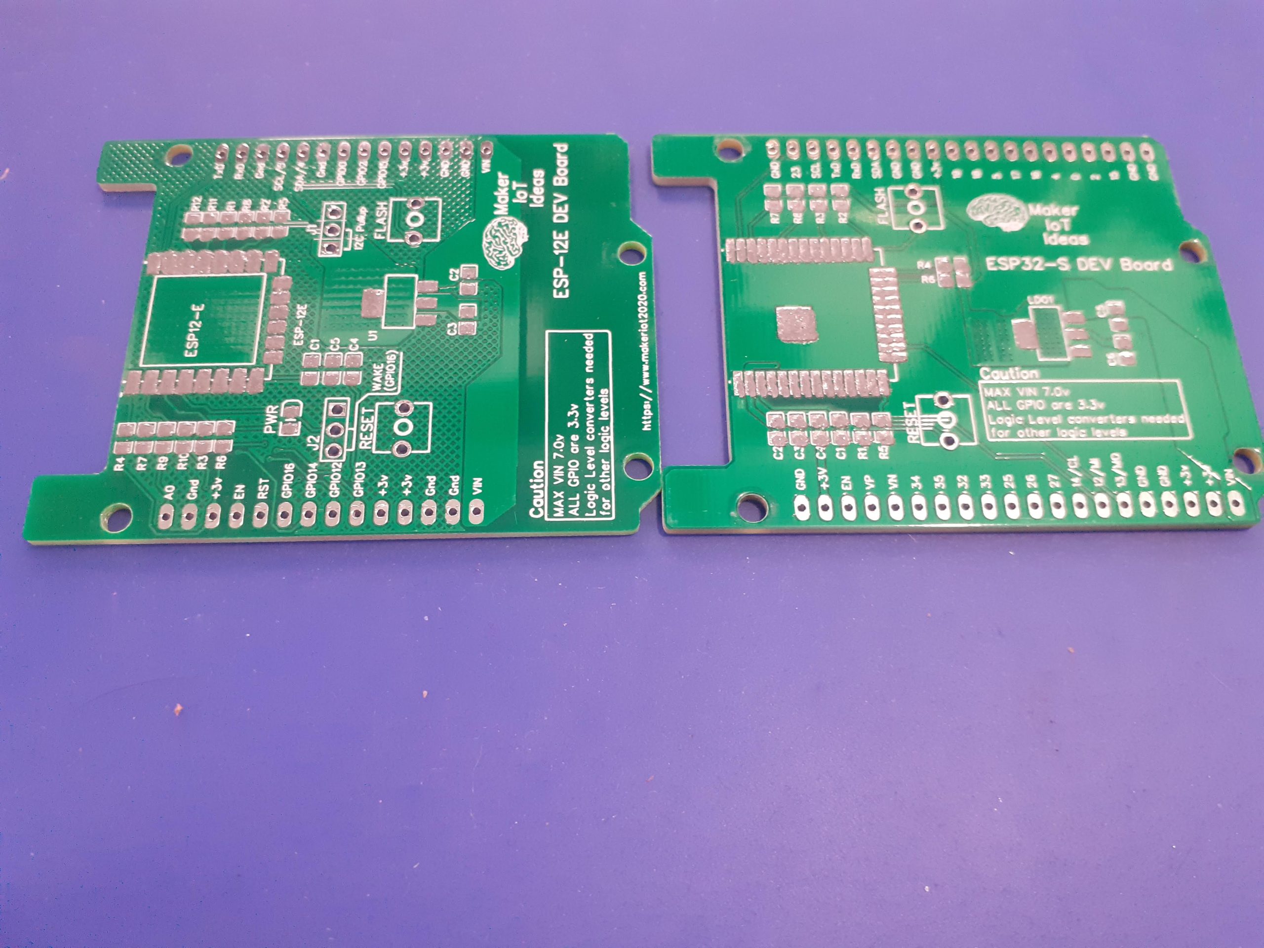
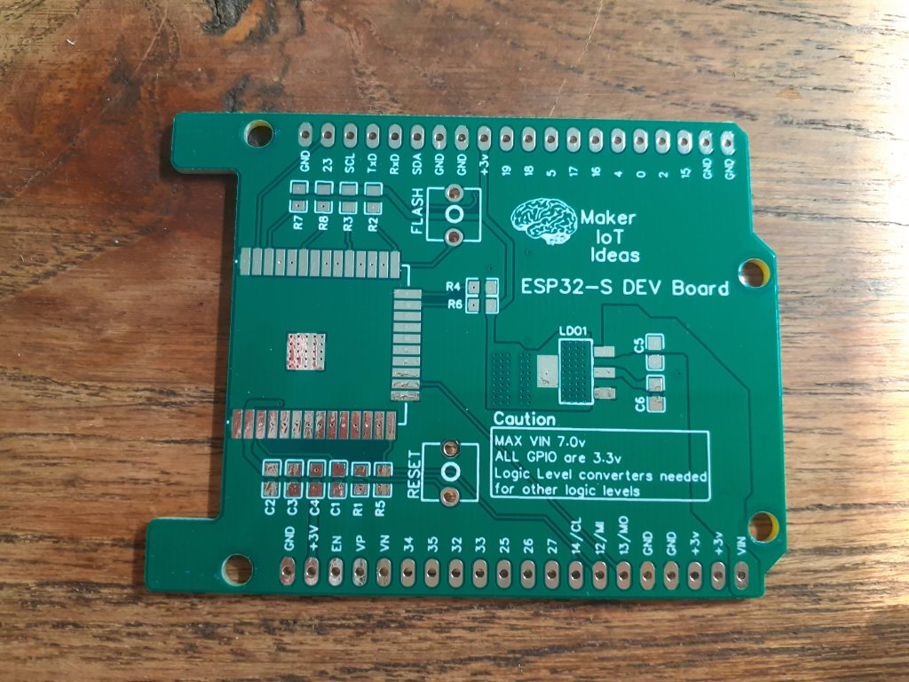 The Blank PCB ( front )
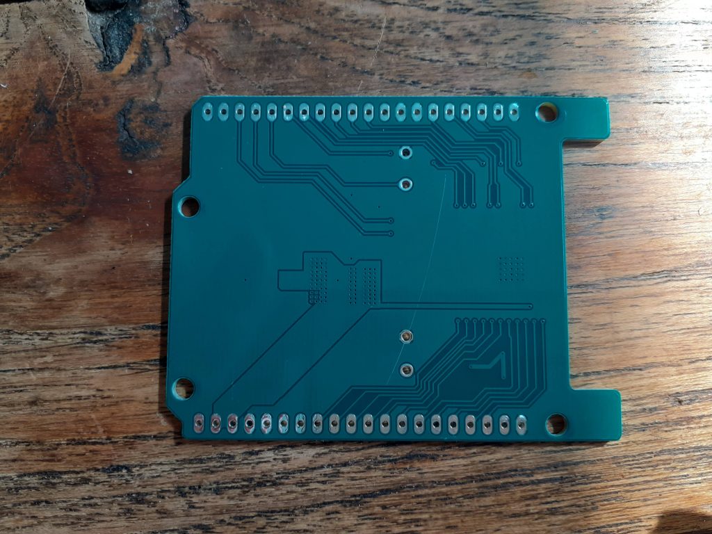 PCB- Back
The PCB explained…
Power:
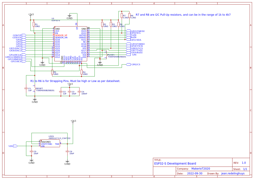
The board can be powered in two ways, either via the VIN pin ( at an optimal 7.0v DC – the LDO regulator can handle up to 15v, but I personally find that to stress it a bit hard ), which will use the onboard LDO voltage regulator to provide the needed 3.3v or from an external 3.3v PSU, which can provide a bit more current if needed…
There are also plenty of 3.3v and ground connections on the two 20-way headers to connect to other sensors.
Strapping Pins
All the required strapping pins are pulled up or pulled down, as per the datasheet, to 3.3v or ground respectively.
GPIO Pins
All GPIO pins are clearly labelled on the silkscreen to make it easier to use.
I did however not stick to the Arduino labelling convention, as I don’t always use the Arduino IDE, and the actual GPIO numbers are in my view, more useful then.
Flashing code to the board
It will be quite obvious that I did not include any USB-to-serial converter on the board, the reason for this being that, in my opinion,
1) it wastes space on the board
2) it is not actually necessary, as we can upload with an external uart adapter, or use OTA ( which I actually do most of the time )
3) In an actual project, that USB port is going to attract problems, especially if you give it to someone else to use…
A simple Arduino OTA sketch is available in the examples section of the Arduino IDE. It is easy to use and modify and does not need a lot to make it useable with your own sketch…
Antenna Cutout
As recommended by the manufacturer , I have chosen to place the chip inside a cutout on the top of the PCB, with no tracks nearby.
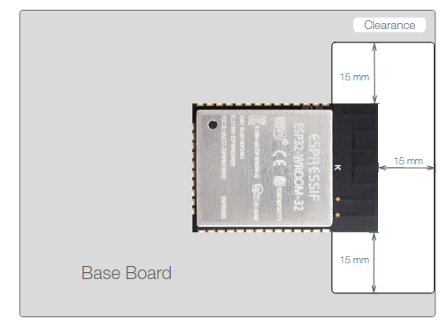 Figure 17: Keepout Zone for ESP32 Module’s Antenna on the Base Board
Although this is not the ideal “best position”, I found that this position worked well with previous designs, and have thus kept it at that.
General comments
As this board is mainly designed for prototype development, I did not bother with dedicated power connectors etc. I did however add proper wide tracks for all the power connections, an on-PCB-heatsink for the voltage regulator, as well as proper ground planes on both sides of the PCB, connected together with via-stitching where needed.
It is also very important to note that this is a 3.3v device. If you need to use sensors or peripherals that operate at other voltages, you will have to use external level converters.
Some assembly pictures
 After Solderpaste application
 Before Reflow
 After Reflow
 After final assembly
Schematic
ESP32-S Development Board, in "Arduino Uno" form factor
Project images are for reference only. Actual production is based on the manufacturing files on the project page.
Please review the designer's notes (e.g., PCB thickness) and select the appropriate options.
PCBWay is not responsible
for issues caused by unsuitable parameter selections.
For more important ordering information, please refer to
Read More


Raspberry Pi 5 7 Inch Touch Screen IPS 1024x600 HD LCD HDMI-compatible Display for RPI 4B 3B+ OPI 5 AIDA64 PC Secondary Screen(Without Speaker)
BUY NOW


- Comments(4)
- Likes(21)
- 1 USER VOTES
- YOUR VOTE 0.00 0.00

-
10design
-
7usability
-
10creativity
-
10content
More by Jean Redelinghuys MakerIoT2020
-
 PCB_MCP23008_2023-10-08
MCP23008 BreakoutI designed this breakout to assist me during prototyping my next version of the “RP...
PCB_MCP23008_2023-10-08
MCP23008 BreakoutI designed this breakout to assist me during prototyping my next version of the “RP...
-
 PCB_XiaoRP2040-Mouse-REV2
Xiao RP2040 Joystick Mouse – revision 2.00Revision 1.0 of the ProjectOver the last few months, I hav...
PCB_XiaoRP2040-Mouse-REV2
Xiao RP2040 Joystick Mouse – revision 2.00Revision 1.0 of the ProjectOver the last few months, I hav...
-
 Multi Purpose IO Card
Multi-Purpose IO CardWhen we are working on a prototype, we always need access to pushbuttons, encod...
Multi Purpose IO Card
Multi-Purpose IO CardWhen we are working on a prototype, we always need access to pushbuttons, encod...
-
 Variable Voltage Power Module
Powering electronics projects are always challenging. This Variable vol...
Variable Voltage Power Module
Variable Voltage Power ModulePowering electronics projects are always challenging. This Variable vol...
-
 I2C Matrix Keypad
An I2C Matrix KeypadThe completed I2C Matrix KeypadIn a previous post this month I introduced my 4×4...
I2C Matrix Keypad
An I2C Matrix KeypadThe completed I2C Matrix KeypadIn a previous post this month I introduced my 4×4...
-
 ESP32-S Development Board, in "Arduino Uno" form factor
UPDATE 24/06/2023:This board now has a Hardware Revision 2.0 available. It is the same board but wit...
ESP32-S Development Board, in "Arduino Uno" form factor
UPDATE 24/06/2023:This board now has a Hardware Revision 2.0 available. It is the same board but wit...
-
 W307186ASC94_Gerber_PCB_USB-Ports
USB Power Supply ModuleUSB Ports are quite handy to power all our day-to-day electronic devices, but...
W307186ASC94_Gerber_PCB_USB-Ports
USB Power Supply ModuleUSB Ports are quite handy to power all our day-to-day electronic devices, but...
-
 Atmega 328P based PWM controller Card
ATMega 328P Based PWM controller CardAs part of my recent ESP-12E I2C Base Board project, I designed...
Atmega 328P based PWM controller Card
ATMega 328P Based PWM controller CardAs part of my recent ESP-12E I2C Base Board project, I designed...
-
 W307186ASC71_Gerber_PCB_ESP-Now Remote
Today we will look at the remote control unit for the Robotic Toy Car – Part 6.The project is close ...
W307186ASC71_Gerber_PCB_ESP-Now Remote
Today we will look at the remote control unit for the Robotic Toy Car – Part 6.The project is close ...
-
 W307186ASV69_Gerber_PCB_Robot-Car-MCU-Board Prototype
In our last project, we started working on repurposing an old toy car. In this part, Robot Toy Car –...
W307186ASV69_Gerber_PCB_Robot-Car-MCU-Board Prototype
In our last project, we started working on repurposing an old toy car. In this part, Robot Toy Car –...
-
 W307186ASV62_Gerber_PCB_DUAL-H-Bridge
by makeriot2020 on May 27, 2022Many of us have old toys laying around the house, they belong to ou...
W307186ASV62_Gerber_PCB_DUAL-H-Bridge
by makeriot2020 on May 27, 2022Many of us have old toys laying around the house, they belong to ou...
-
 CAN-BUS Breakout
Breadboard Compatible CAN-BUS Breakout ModuleWhat is this:Some of us have already used the commonly ...
CAN-BUS Breakout
Breadboard Compatible CAN-BUS Breakout ModuleWhat is this:Some of us have already used the commonly ...
-
 RA-02 Breakout with Level converters
Breadboard and beginner-friendly RA-02 Breakout ModuleMost Makers and electronics enthusiasts may al...
RA-02 Breakout with Level converters
Breadboard and beginner-friendly RA-02 Breakout ModuleMost Makers and electronics enthusiasts may al...
-
 ATMEGA328P Module with integrated LoRa and CAN Bus
ATMEGA328P Module with integrated LoRa and CAN-BUSINTRODUCTIONIn my quest to perfect my LoRa telemet...
ATMEGA328P Module with integrated LoRa and CAN Bus
ATMEGA328P Module with integrated LoRa and CAN-BUSINTRODUCTIONIn my quest to perfect my LoRa telemet...
-
 Sx127x-Ra-02-Test-Module with ATMEGA328P-AU
SX127x LoRa/FSK/OOK Prototype Radio BoardI recently had a requirement to do some automation/telemetr...
Sx127x-Ra-02-Test-Module with ATMEGA328P-AU
SX127x LoRa/FSK/OOK Prototype Radio BoardI recently had a requirement to do some automation/telemetr...
-
 USB-ASP Programmer ATMEGA8
Build your own USB-ASP Programmer CloneBymakeriot2020 FEB 21, 2022 Arduino, ASP programmerUsing mor...
USB-ASP Programmer ATMEGA8
Build your own USB-ASP Programmer CloneBymakeriot2020 FEB 21, 2022 Arduino, ASP programmerUsing mor...
-
 ATTiny1616-LIGHT-Controller-with-CAN_B_PCB_ATTiny1616-LIGHT-Controller-with-C_2024-09-11
Assembly of the ATTiny1616 Can bus controller PCBThe Assembly of the ATTiny1616 Can Bus Controller P...
ATTiny1616-LIGHT-Controller-with-CAN_B_PCB_ATTiny1616-LIGHT-Controller-with-C_2024-09-11
Assembly of the ATTiny1616 Can bus controller PCBThe Assembly of the ATTiny1616 Can Bus Controller P...
-
 ATTiny1616QFN-CAN-Remote-Neopixel-Ligh_PCB_ATTiny1616QFN-CAN-Remote-Neopixel-2024-09-11_2024-09-11
NeoPixel CAN-Bus Module with local controlAs part of my current project to add NeoPixels to the cabi...
ATTiny1616QFN-CAN-Remote-Neopixel-Ligh_PCB_ATTiny1616QFN-CAN-Remote-Neopixel-2024-09-11_2024-09-11
NeoPixel CAN-Bus Module with local controlAs part of my current project to add NeoPixels to the cabi...
-
Programmable Mist Maker - XIAO / QT PY Extension
1061 2 1 -
RadioHAT - Raspberry Pi radio development platform
860 0 2 -
-
-
-
-
ARPS-2 – Arduino-Compatible Robot Project Shield for Arduino UNO
3322 0 6 -
A Compact Charging Breakout Board For Waveshare ESP32-C3
3930 3 8 -
AI-driven LoRa & LLM-enabled Kiosk & Food Delivery System
4315 2 2


