


|
|
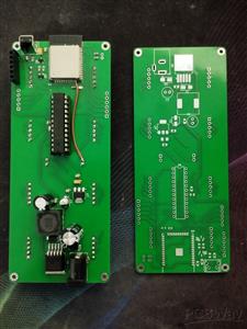
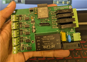
ESP32-WROOM-32D (4MB)ESPRESSIF
|
x 1 | |
|
|
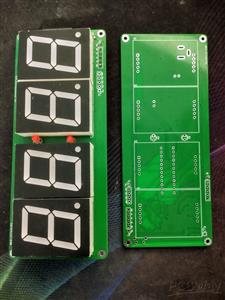
MAX7219CNG+Analog Devices (MAXIM INTEGRATED)
|
x 1 | |
|
|
LM2596S-5.0/NOPB |
x 1 |

|
KiCad 9.0 |
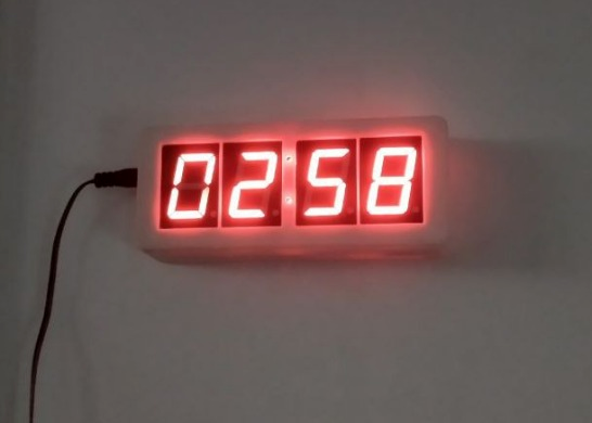
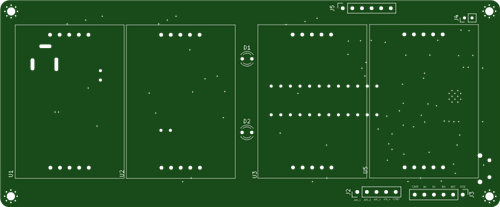
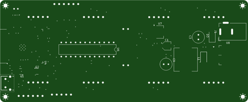
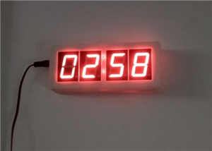
Smart Clock
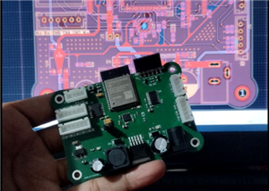
This project is a Wi-Fi-enabled digital clock built around an ESP32 module that drives a four-digit MAX7219 7-segment display to show real-time hours, minutes, and seconds. A responsive web interface, served by the microcontroller, allows you to set the time, alarms, countdowns, timezone, and home-network credentials. Meanwhile, a buzzer and physical button provide audible alerts and quick dismissal. Running in dual AP/STA mode, the clock creates its own setup hotspot, reconnects to your home Wi-Fi for hourly SNTP synchronization, and stores all settings in NVS for stand-alone, always-accurate operation.
Smart Clock
Project images are for reference only. Actual production is based on the manufacturing files on the project page.
Please review the designer's notes (e.g., PCB thickness) and select the appropriate options.
PCBWay is not responsible
for issues caused by unsuitable parameter selections.
For more important ordering information, please refer to
Read More

- ✖ | No sharing or redistributing in any way of the 3D files or derivatives
- ✖ | No remixing
- ✖ | Non-commercial Use (only for personal use)


Raspberry Pi 5 7 Inch Touch Screen IPS 1024x600 HD LCD HDMI-compatible Display for RPI 4B 3B+ OPI 5 AIDA64 PC Secondary Screen(Without Speaker)
BUY NOW


- Comments(0)
- Likes(0)
More by Avishka Vishwajith
-
 ESP AutoBoard_32
Hardware Capabilities5 Optocoupler Inputs: 12V-24V isolated inputs using PC817/PC827 optocouplers4 S...
ESP AutoBoard_32
Hardware Capabilities5 Optocoupler Inputs: 12V-24V isolated inputs using PC817/PC827 optocouplers4 S...
-
 Smart Clock
This project is a Wi-Fi-enabled digital clock built around an ESP32 module that drives a four-digit ...
Smart Clock
This project is a Wi-Fi-enabled digital clock built around an ESP32 module that drives a four-digit ...
-
 RoboCore 2.0 - ESP32-S3 Robotics Controller
RoboCore 2.0 – ESP32-S3 Robotics Controller BoardRoboCore 2.0 is my second-generation robotics contr...
RoboCore 2.0 - ESP32-S3 Robotics Controller
RoboCore 2.0 – ESP32-S3 Robotics Controller BoardRoboCore 2.0 is my second-generation robotics contr...
-
 DC Motor Speed Controller
12V DC Motor Speed Controller – PCB Design using KiCADThis project showcases a compact, efficient, a...
DC Motor Speed Controller
12V DC Motor Speed Controller – PCB Design using KiCADThis project showcases a compact, efficient, a...
-
Programmable Mist Maker - XIAO / QT PY Extension
1074 2 1 -
RadioHAT - Raspberry Pi radio development platform
890 0 2 -
-
-
-
-
ARPS-2 – Arduino-Compatible Robot Project Shield for Arduino UNO
3334 0 6 -
A Compact Charging Breakout Board For Waveshare ESP32-C3
3944 3 8 -
AI-driven LoRa & LLM-enabled Kiosk & Food Delivery System
4330 2 2


