


|
KiCad 9.0 |
|
|
|
FreeCADFree Software Foundation, Inc.
|
|
|
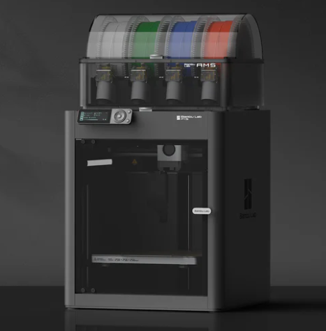
Bambu Lab P1S 3D PrinterBambu Lab
|
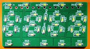
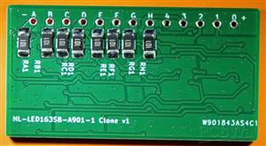
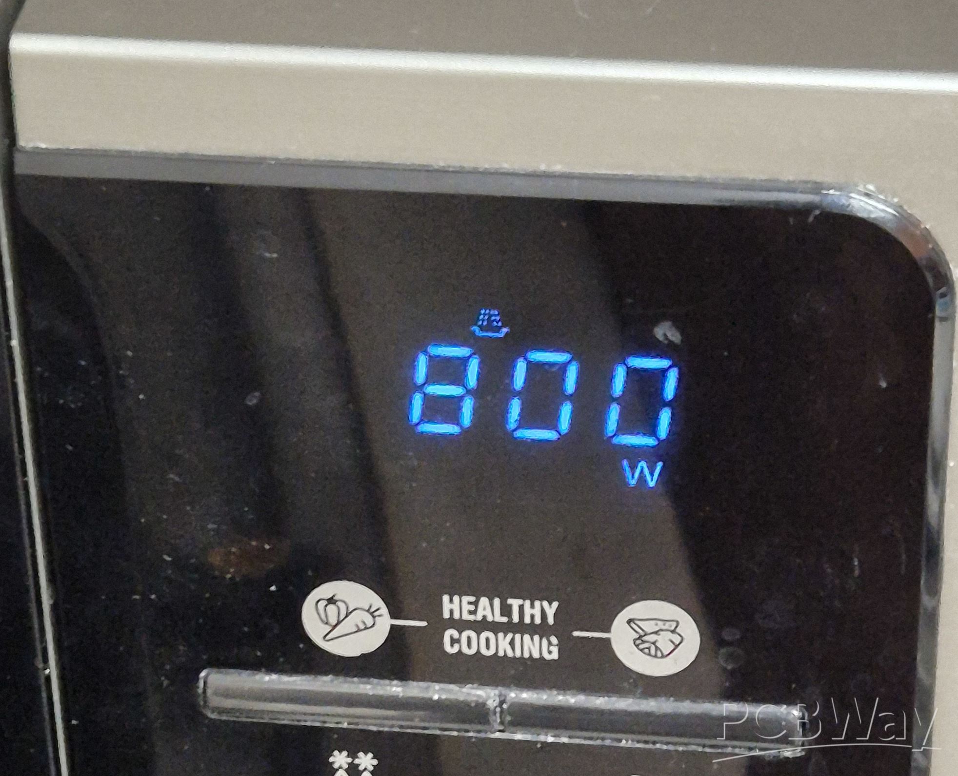
Samsung Microwave Display HL-LED163SB-A901-1 Replacement
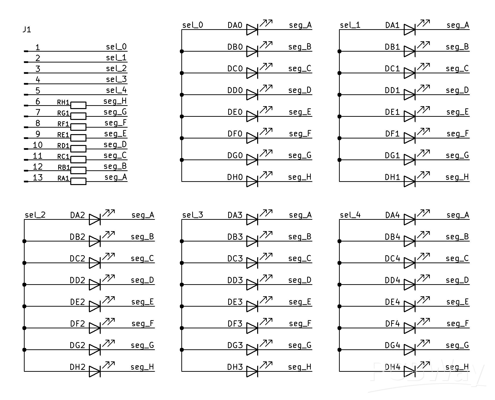
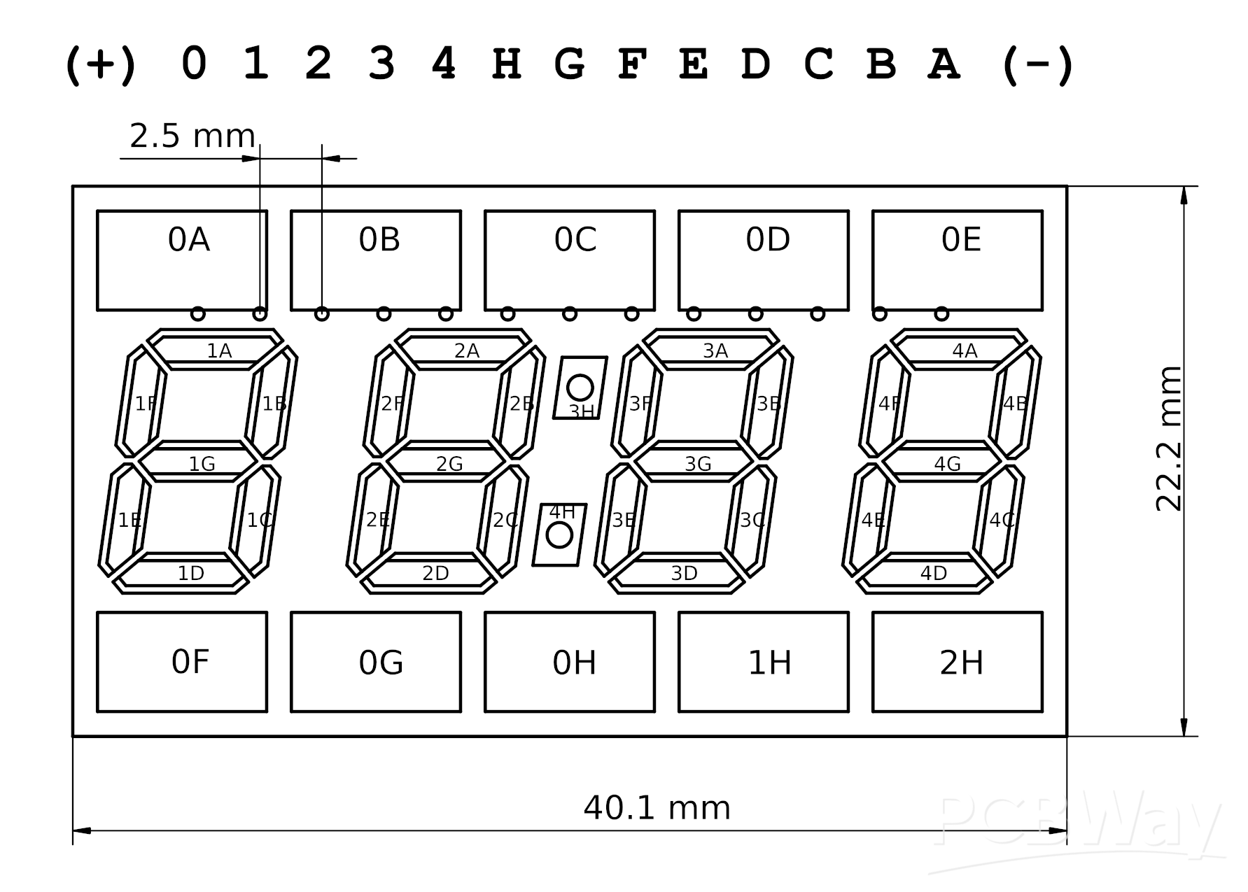
Many Samsung microwave ovens use HL-LED163SB series 7-segment displays, which are clearly custom made and not available for purchase as parts. Sometimes a single LED segment burns out, which happened to my microwave, so I decided to make a DIY replacement.
NOTE: Since I assembled manually, the included BOM is a placeholder and doesn't fill the fields required to specify exact components to be used for PCBA.
The enclosure is designed for the display PCB manufactured with 1.2 mm thickness.
Necessary components:
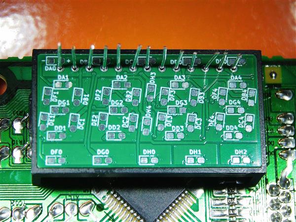
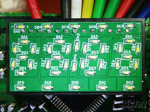
- 40* 0603 White LEDs, rated brightness ~900mcd at 20mA, e.g. Nationstar NCD0603W1-XA
- 8* 1206 resistors, sized to ensure current doesn't exceed 20mA at 5V supply, around 100-120 ohm
- 3D printed diffuser enclosure
- Original faulty part for reusing the blue tinted filter sticker with symbols
- 22 AWG tin plated copper wire for connector pins
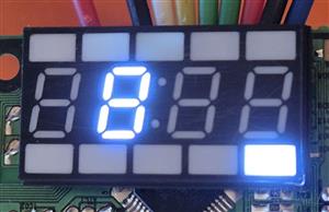
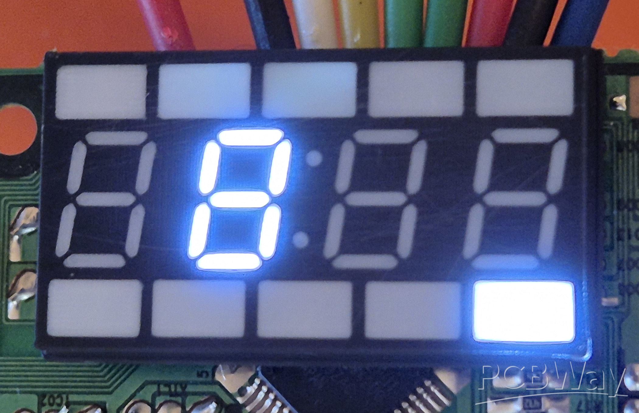
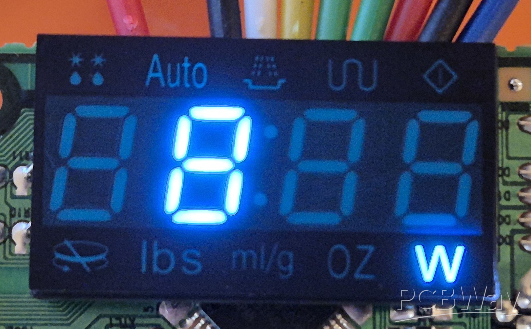
This display actually uses white LEDs and tints them using a sticker applied to its front, which also contains a black mask defining the special function symbols. This sticker can be carefully peeled off and reapplied to the 3D print. Based on images from the web, I suspect A901 in the part name refers to the symbols on the sticker, so this board and enclosure should probably work for all HL-LED163SB parts.
I used LEDs from AliExpress that claim 150-170 mcd brightness, which turned out to be usable but too dim to look good in a well lit environment, so I recommend at least double that value, or possibly more (I'm not sure how exactly that difference translates into perceived brightness).
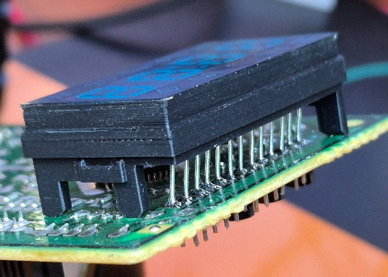
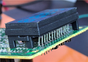
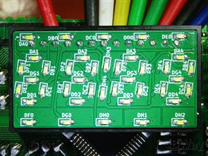
When installing the board I found that I originally made a mistake in measuring the position of the pins, resulting in a 1.5 mm offset, and requiring bending the pins, as can be seen in the photos. The board files I upload here are a fixed version where this error was corrected, so technically they are untested; however the schematic wasn't changed and the fixed layout passes DRC.
Update: After half a year the AliExpress LEDs very noticeably faded, with one of them becoming nearly invisible, so I felt justified to order some brighter ones from a named manufacturer, specifically Nationstar NCD0603W1-XA from LCSC, rated typical 960 mcd @ 20mA. I also used an oscilloscope to verify the voltage and multiplexing frequency: it turns out the board runs the display using 1ms pulses of ~4V (when in standby mode) or 4.4V (when actively using buttons) with 4-5ms gaps (20% duty cycle). With a 120 ohm resistor to limit the 4V pulse current to 10mA I feel the new LEDs seem to have perfect brightness: not too bright but the clock is easily readable from a few meters away. Hopefully they are more reliable than the old ones.
Enclosure (MakerWorld or attached below)
The diffusing enclosure is a delicate print that uses multiple materials, so it requires a printer with that capability and manual oversight during the print process. I used Bambu P1S with AMS and a 0.2 mm nozzle. To make the replacement serviceable in case of problems, the enclosure consists of two parts with a friction fit reinforced by layer lines meshing.
Diffuser Cap
The diffuser consists of a single 0.05 mm thick layer of white PETG sandwiched inside translucent PETG for structural strength and extra diffusion, and housed inside a black PETG body.
The first printed layer is a continuous translucent rectangle, designed to protect the white layer from the front and prevent bed adhesion issues. This layer is ironed to remove the line pattern from the top surface. It is important to calibrate the general material extrusion and ironing flow.
The second layer contains the white openings surrounded by black mask. The print quality of this white layer is critical, so material and ironing flows must be calibrated as precisely as possible. Due to extra material deposited by ironing the first layer the material flow may need to be lowered from the normal calibrated value, however it is very important to avoid under-extrusion causing pinholes in or around the white symbols. It is also necessary to watch for any white blobs or stringing compromising the outlines and cancel the print if it can't be removed manually during the switch from white to black filament, as that distortion will be visible from the front.
After the second layer is complete, the profile is configure to pause. During the pause use a curved exacto blade to scrape the surface of the white layer from any blobs or over-extrusion and make it as smooth as practical. Variations in the thickness of this layer directly cause variations in brightness.
The print also pauses after the 3rd layer for inspection, but scraping is not required unless black strings or blobs intrude on the transparent areas. Continue to monitor for this during the following layers to prevent trapping black material inside transparent plastic.
After the print completes, optionally sand and polish the front surface on a sequence of sand paper grits to remove the vestiges of the print line pattern and/or glue unevenness.
Board Support Frame
The frame that supports the display board at the correct distance from the main PCB is a much simpler print. It only uses a manually designed PLA interface spacer to separate supports from the part surface.
Calibration Tests
The file contains three calibration tests to help in getting the settings right.
The first one tests various ironing flow values for the first layer. After completing it and checking the best value apply it to the Face part of other tests and the main print object.
The second one tests ironing flow for the bulk of the diffuser. The goal is to select enough flow to suppress the normal print line pattern and produce uniformly foggy appearance. Apply the selected flow value to the "0.22-3.90" layer range modifier of the main print object.
The third test is for choosing the flow rate for the white plastic, as well as its ironing speed and flow. Adjust the flow in the material based on the non-ironed column, and apply the chosen ironing settings to the 0.10 to 0.22 layer range modifiers.
Despite these tests, it is a good idea to print and check the first layers of the real object by cancelling the print when it pauses after the 2nd or 3rd layer. Try to avoid over-extrusion, but absolutely avoid pinprick holes.
Assembly
Cut pins from 22 AWG wire and solder them to the main PCB. Use the printed support frame and a spare unpopulated display PCB to fully align them and trim almost flush to the display board. If the board doesn't fully fit into the frame, sand it.
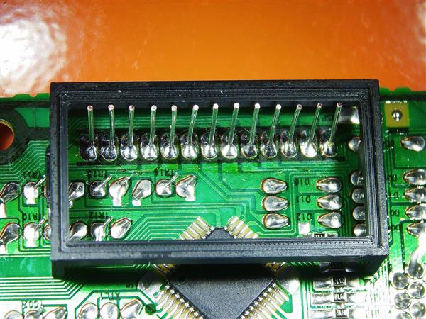
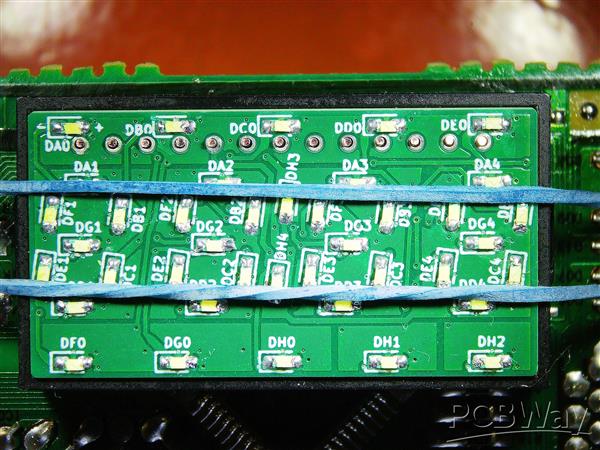
Replace the spare with the real board and solder it to the pins without excess solder blobs: the enclosure should accomodate protrusions within the diameter of the pads and up to 0.5mm thickness from the board. It helps to use a rubber band to ensure the display board and frame are firmly seated during soldering.
Put the diffuser cap on the installed frame and board and ensure it is fully seated and not obstructed by excessively protruding pins. Carefully peel the sticker from the original display and apply it to the cap. Optionally, additionally secure the cap to the frame with tape.
After installing the PCB into the housing from the microwave it may be a good idea to reach in with tweezers or a screw driver and check that the cap is still fully seated and wasn't dislodged when the board snapped into its plastic holders.
Samsung Microwave Display HL-LED163SB-A901-1 Replacement
*PCBWay community is a sharing platform. We are not responsible for any design issues and parameter issues (board thickness, surface finish, etc.) you choose.


Raspberry Pi 5 7 Inch Touch Screen IPS 1024x600 HD LCD HDMI-compatible Display for RPI 4B 3B+ OPI 5 AIDA64 PC Secondary Screen(Without Speaker)
BUY NOW


- Comments(0)
- Likes(0)
 More by A.N. G.
-
Programmable Mist Maker - XIAO / QT PY Extension
561 1 0 -
RadioHAT - Raspberry Pi radio development platform
440 0 1 -
-
-
-
-
ARPS-2 – Arduino-Compatible Robot Project Shield for Arduino UNO
2951 0 6 -
A Compact Charging Breakout Board For Waveshare ESP32-C3
3466 3 8 -
AI-driven LoRa & LLM-enabled Kiosk & Food Delivery System
3810 2 2


