


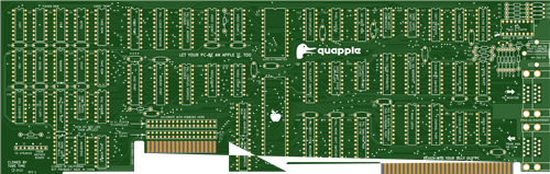
Quapple- A Quadlink Clone
GITHUB
https://github.com/schlae/quapple
Please note that the 0.1" header pins are not listed on the BOM. They are standard breakaway headers.
The memory chips (4416 and 4164 RAM) are both 150ns types.
Fab Files
Fabrication Notes
This board is a straight forward 2-layer board. Ideally you should specify selective gold plating (hard gold) for the edge fingers, but this gets very expensive for small orders. ENIG will work but the gold will rub off fairly quickly.
Board dimensions are 13.335" x 4.24" (338.7mm x 107.7mm).
For the soldermask color, pick whatever you want!
Assembly Notes
I recommend using sockets for the memory chips, CPU, and all the PALS. You'll also need a socket for the joystick/paddle connector. The list of sockets required is as follows:
QuantityPositionType9U1-U4, U20-U23, J416-pin, 0.3" wide2U5, U2418-pin, 0.3" wide1U1124-pin, 0.6" wide1U4840-pin, 0.6" wide10U7, U8, U27, U30, U33, U34, U40, U49, U50, U5120-pin, 0.3" wide
If you plan to install the card in an IBM 5150 or 5160, you'll plug the floppy drive cable (the one going between the existing controller and the floppy drives in your computer) into the P2 edge connector on the card. Solder a shrouded header at the J7 position with the keying notch pointing downwards. Later on, you'll make a short cable to go between the floppy controller card and J7.
If you want to use the card in another system (note: I have not tested this yet!) with a standard IDC header instead of an edge card connector, solder unshrouded headers at both the J7 and P3 position. Your existing floppy cable will plug into P3, and you will need to make a short cable that connects J7 and your existing floppy controller card.
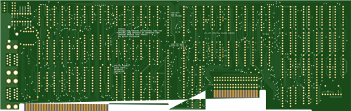
J5 and J6 are right-angle 0.1" headers. You can use a single 8-pin strip. Remember to pull pin 2 on both header positions since this is the key for the cable that plugs in. This is also marked on the back of the PC board.
If you are using an NMOS 6502, you can connect the solder jumper on the back of the board right next to the chip. CMOS 6502 chips repurpose this pin and the solder jumper should be left open.
Note for European users: it might be tempting to configure the solder jumpers on the back of the card for PAL timings rather than NTSC, but I have not tested this configuration. The original Quadlink has solder paste covering the jumpers, implying that they never fully tested it. Use it at your own risk.
Bracket
I've created a CAD model of the original Quadlink bracket. If you have access to sheet metal tools (or even just a chassis nibbler) then you can reproduce it. Once it is in the right shape, bend the top using a press brake or even just a bench vise. The material is 0.035" (0.9mm) steel, brushed and painted black.
CAD drawing of bracket
Programmable Devices
There are 11 programmable devices on the Quapple. One of them is a 27C32 EPROM which contains the character set for the text mode. I didn't have much luck using the Minipro TL866 device to program my Intel 2732 devices, so you might have to try a few to find one that works. You might also try using a flash device (28C32?) instead, but I have not tested this myself.
EPROM binary
The remaining programmable devices are all PALs. You can use an ATF16V8 (speed grade is unimportant here), which happens to be supported by the Minipro TL866.
PAL files
Use the JEDEC files (.jed) with the following Minipro command line under Linux:
minipro -p "ATF16V8B" -w [file.jed] -P
The full, commented, PAL source code is provided for educational purposes. If you want to modify them, you can use WinCUPL to build them.
I recommend marking the PALs with colored dots, labels, or permanent marker so you don't mix them up and put them in the wrong sockets.
PAL functions are as follows:
PositionFunctionU8Video address decoding (simple)U27Video address decoding (complex). Video sync.U7Clock generationU30Soft switchesU33Color attribute generationU34ISA bus address decoderU40Disk controllerU496502 state machineU50More soft switchesU51RAM/ROM mapping, CAS control, RESET inverter
Cable assemblies
You will also need to build several cable assemblies to connect the Quapple to your PC.
Floppy drive cable
For use with an IBM 5150 or 5160, make a short, 6" (15cm) IDC ribbon cable, 34 pin, with a 0.1" female header at one end and a 34-pin female edge connector at the other end.
For any other computer, just crimp a 34-pin 0.1" female header at both ends. Be sure not to get pin 1 mixed up--it is very easy to do!
Video loopback cable
To use the same monitor for both Apple and PC mode, you'll need a short cable to go between the Quapple and your regular video card (MDA or CGA). This is just a short cable with a male DE-9 connector at both ends, wired straight through (pin 1 to pin 1, etc).
The stock cable is 12" (30.5cm) long and uses a TE Connectivity/AMP 745032-1 connector, along with a cord guard, 207753-1, at both ends. The contact part number is 1-66506-0. The cable is 0.24" (6mm) diameter with eight conductors (the drain wire is connected to pin 1).
PC speaker jumper
To hear Apple sound through the PC speaker, make a short 2-wire cable (maybe 2-3" long, depending on your computer). This goes from the motherboard to the Quapple.
The cable should be wired as follows:
Pin 1 connects to pin 1 (black wire)
Pin 2 is a key (plastic peg inserted in the opening) at both ends
Pin 3 is not used
Pin 4 to pin 4 (yellow wire)
Installation
You'll want to install the card in the second-to-last slot (5150) or third-from-last slot (5160). This is because the floppy controller should be in between the Quapple and the power supply, just to make cable routing easier.
Before you start, plug the short floppy jumper cable into J7 on the Quapple. Also plug the 4-pin PC speaker jumper cable into header J6.
Remove the floppy controller and disconnect the drive cable from it. Plug the drive cable into the Quapple connector P2 (or P3, if the cable has a 0.1" socket at the end). Unplug the PC speaker from the motherboard.
Then plug the Quapple into the PC slot, managing the floppy cable as needed. The 4-pin jumper should plug into the motherboard's PC speaker header, and the PC speaker cable should plug into J5.
Then plug the short floppy jumper cable into the header on the floppy controller, and plug the floppy controller back into an adjacent slot. Since the card is shorter, it's much easier to use the slot that is closer to the power supply.
Finally, connect the DE-9 jumper cable between the video card and the lower connector on the Quapple. This step is optional since you can use the card with a dual monitor configuration, or even with the composite video output jack.
Software
You can find the software at the link below, along with the manual of the original Quadlink. There are three disk images you will need: the Quadlink System Master, the Quadlink Filer, and DOS (I used PC DOS 1.10, but feel free to experiment). The Quadlink System Master disk has an executable, QUADLINK.EXE, which should be copied to the DOS disk.
The Filer disk can be written using a flux imaging tool, or possibly with an Apple II running ADTPro.
Software download
A note about compatibility: I have only tested the card in an IBM 5150. It's supposed to work in a 5160 as well. Based on looking at the design, I see no reason why it wouldn't work in a faster machine, but there may be CPU-dependent hardware loops in the Quadlink executable that would prevent it from working.
Once you have the disks, insert the DOS disk and turn on the computer. After it boots, run QUADLINK.EXE and follow the prompts. When you insert the Filer disk, the software copies the entire Applesoft ROM from the disk into a special 16K memory on the card and write-protects it. Hit a key to get back to DOS, and then press CTRL-ALT-A. If you see the Quadlink banner, hit CTRL-ALT-DEL to boot the Apple.
Troubleshooting
This can be a tricky card to troubleshoot. The QUADLINK.EXE doesn't really provide good error diagnostics, but if you can get it to access the Filer disk, then you know that the 6502 is running code and trying to copy data from the disk.
Someday, when I get a chance, I'll look into writing a diagnostic program to help with the process...
License
This work is licensed under a Creative Commons Attribution-ShareAlike 4.0 International License. See https://creativecommons.org/licenses/by-sa/4.0/.
Quapple- A Quadlink Clone
*PCBWay community is a sharing platform. We are not responsible for any design issues and parameter issues (board thickness, surface finish, etc.) you choose.


Raspberry Pi 5 7 Inch Touch Screen IPS 1024x600 HD LCD HDMI-compatible Display for RPI 4B 3B+ OPI 5 AIDA64 PC Secondary Screen(Without Speaker)
BUY NOW

- Comments(0)
- Likes(5)
-
 Necroware S7-VRM (2024 Version)
Note from PCBWay: There are some problems in the BOM on the project page that cannot be resolved. If...
Necroware S7-VRM (2024 Version)
Note from PCBWay: There are some problems in the BOM on the project page that cannot be resolved. If...
-
 Atari 2600 PlusCart
Original Site: https://gitlab.com/firmaplus/atari-2600-pluscart
Atari 2600 PlusCart
Original Site: https://gitlab.com/firmaplus/atari-2600-pluscart
-
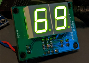 2 digit Turbo Display
Original GITHUB: https://github.com/wiretap-retro/2-digit-Turbo-Display?tab=readme-ov-file#2-digit-t...
2 digit Turbo Display
Original GITHUB: https://github.com/wiretap-retro/2-digit-Turbo-Display?tab=readme-ov-file#2-digit-t...
-
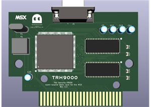 TRH9000 - a graphics expansion cartridge for MSX
Original GITHUB: https://github.com/cristianoag/trh9000
TRH9000 - a graphics expansion cartridge for MSX
Original GITHUB: https://github.com/cristianoag/trh9000
-
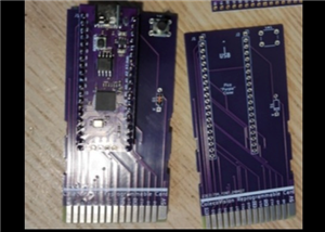
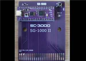 SD-1000 - Sega flash multicart for SC-3000, SG-1000 and Mark III based on Pico Clone
Original GITIHUB: https://github.com/aotta/SD-1000
SD-1000 - Sega flash multicart for SC-3000, SG-1000 and Mark III based on Pico Clone
Original GITIHUB: https://github.com/aotta/SD-1000
-
 PiCOLECO - a Colecovision flash multicart based on Pico clone
Original GITHUB: https://github.com/aotta/PiCOLECO
PiCOLECO - a Colecovision flash multicart based on Pico clone
Original GITHUB: https://github.com/aotta/PiCOLECO
-
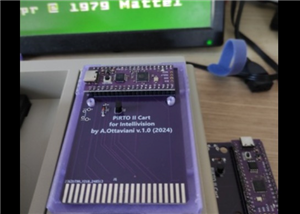 Pi-RTO II - a Intellivision flash multicart based on Pico clone
Original GITHUB: https://github.com/aotta/PiRTOII
Pi-RTO II - a Intellivision flash multicart based on Pico clone
Original GITHUB: https://github.com/aotta/PiRTOII
-
 PicoPAC - Flash Multicart for Philips Videopac (Magnavox Odyssey 2)
Original GITHUB: https://github.com/aotta/PicoPACMore info: https://www.nightfallcrew.com/22/09/202...
PicoPAC - Flash Multicart for Philips Videopac (Magnavox Odyssey 2)
Original GITHUB: https://github.com/aotta/PicoPACMore info: https://www.nightfallcrew.com/22/09/202...
-
 PicoMSX (Pico MSX Not MSXPico)
ORIGINAL GITHUB: https://github.com/Chandler-Kluser/picomsxThis project is on development by his aut...
PicoMSX (Pico MSX Not MSXPico)
ORIGINAL GITHUB: https://github.com/Chandler-Kluser/picomsxThis project is on development by his aut...
-
 MSX Goauld Rev. 4.1
Original GITHUB: https://github.com/jabadiagm/MSXgoauld_tn20k
MSX Goauld Rev. 4.1
Original GITHUB: https://github.com/jabadiagm/MSXgoauld_tn20k
-
 Atari 7800 Mini Ultra Rev. D Game Cart
Please see the AtariAge forum: https://forums.atariage.com/topic/69710-the-7800-cartridge-board-thre...
Atari 7800 Mini Ultra Rev. D Game Cart
Please see the AtariAge forum: https://forums.atariage.com/topic/69710-the-7800-cartridge-board-thre...
-
 286 Booster from Necroware
Original GITHUB:https://github.com/necroware/287-boosterCredits to Necroware.
286 Booster from Necroware
Original GITHUB:https://github.com/necroware/287-boosterCredits to Necroware.
-
 MSX SD Mapper v2
ORIGINAL GITHUB: GitHub - fbelavenuto/msxsdmapperv2: MSX SD Mapper Interface V2
MSX SD Mapper v2
ORIGINAL GITHUB: GitHub - fbelavenuto/msxsdmapperv2: MSX SD Mapper Interface V2
-
 Atari 2600 & 7800 Pico Cart Nightfall Version
Original Website: https://www.nightfallcrew.com/17/01/2025/picoa10400-flashcart-for-atari-2600-7800/
Atari 2600 & 7800 Pico Cart Nightfall Version
Original Website: https://www.nightfallcrew.com/17/01/2025/picoa10400-flashcart-for-atari-2600-7800/
-
 Atari XE FULL RA Cart / ECI Extender v2.0
TESTED AND WORKING PERFECT.
Atari XE FULL RA Cart / ECI Extender v2.0
TESTED AND WORKING PERFECT.
-
 Atari 1200XL Extender Cart
Original Website: https://www.bitsofthepast.com/cartridgeboards.html#
Atari 1200XL Extender Cart
Original Website: https://www.bitsofthepast.com/cartridgeboards.html#
-
 Atari 1200XL RA Extender ( Angle Cart )
Original Website: https://www.bitsofthepast.com/cartridgeboards.html#
Atari 1200XL RA Extender ( Angle Cart )
Original Website: https://www.bitsofthepast.com/cartridgeboards.html#
-
 Atari XE ECI port to XL PBI Angle Cart
Original Creator and Website: https://www.bitsofthepast.com/PBI_ECIBoards.html#ATTENTION: This proje...
Atari XE ECI port to XL PBI Angle Cart
Original Creator and Website: https://www.bitsofthepast.com/PBI_ECIBoards.html#ATTENTION: This proje...
-
Programmable Mist Maker - XIAO / QT PY Extension
940 1 0 -
RadioHAT - Raspberry Pi radio development platform
765 0 2 -
-
-
-
-
ARPS-2 – Arduino-Compatible Robot Project Shield for Arduino UNO
3225 0 6 -
A Compact Charging Breakout Board For Waveshare ESP32-C3
3847 3 8 -
AI-driven LoRa & LLM-enabled Kiosk & Food Delivery System
4202 2 2


