


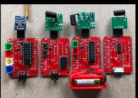


PT226x Remote v1.1
This is a remote encoder board that supports several versions of PT226x encoder chips in a number of configurations.
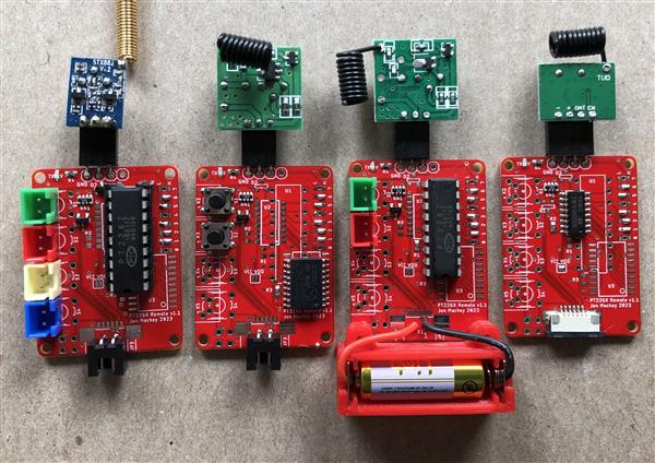
Note that the components needed varies based on the configuration. The components list above is as-needed per your configuration. See configuration notes below.
Encoder Chip
The voltage being supplied and/or how the encoder is being controlled, determines which encoder chips are better suited. For low voltage operation the PT2260-R4S is the choice because it can run on as little as 1.8V. For higher voltage operation, up to 15V, use any of the PT2262 chips.
Supported Encoder Chips
- PT2262 18 pin DIP, 300mil
- PT2262 SOP18, 300mil
- PT2262 SOP20, 300mil
- PT2260-R4S (or equivalent) SOP16, 150mil
Setting the encoded message address
Use the pads labeled 0 to 7 to set the address of the encoded message. Each set of pads can be set to high, low or left floating. The same pattern should be set on your decoder chip (unless you’re using a board with one of the learning decoders, in which case this issue doesn’t apply.)
Transmitter
Any transmitter module can be used provided it tolerates the voltage range you’re using and it has a 3 or 4 pin interface that matches the output on the encoder board (GND, VCC, DATA) and optionally the 4th pin being VCC/EN. The most common transmitter frequencies are 433MHz and 315MHz. source source Antenna source
Control
- Buttons can be soldered directly to the board.
- Buttons can be located off the board using one of the following options:
- button wires soldered directly to board.
- button connected to XH2.5-2P connectors (aka XH2.54)
- buttons connected via a 6 position FFC connector.
- buttons connected via 2x2 2.54 header.
- Instead of buttons, the board can be controlled digitally by a microcontroller connected via a 6 position FFC connector (see below.)
Power
Power can be supplied using one of the following options:
- XH2.5-2P connector
- 6 position FFC connector
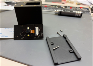
- wires soldered directly to board. See A23 size battery holder in CAD-Custom parts and enclosures below. The battery holder uses AA size plates source. When using, solder the wire to the tab on the plate, then fold the tab over. Insert the plate into the slot in the battery holder (be careful, they bend really easily.) Attach the battery holder to the board using (2) M2x5 button head screws source.
You’ll notice that there are no decoupling capacitors on this board. There is no need for decoupling capacitors because the board is only energized when transmitting an encoded message. Once the user releases the button the board is powered down. This also occurs when the board is controlled by a microcontroller.
Choosing the oscillator resistor value
Each of the encoder chips has its own oscillator resistor. Encoder U1 uses R1, U2 uses R2, and U3 uses R3. The values are based on the recommendation in the documentation for that encoder. The values assume a PT2272 decoder chip with a 820K ohm oscillator resistor. The decoder is somewhat forgiving, but if your decoder is using a significantly different oscillator resistor, follow the guidelines in the encoder documentation to select the correct oscillator resistance value for the encoder you’re using.
For a decoder chip with a 820K ohm oscillator resistor I use a 4.7M ohm oscillator resistor for U1/R1 or U3/R3, and a 10M ohm resistor for U2/R2.
Controlling the board via buttons
When controlling the board by buttons, either on board or external, dual diodes D1 and D2 are used. You only need to install diode D1 if buttons are connected to signals D0 and/or D1. You only need to install diode D2 if buttons are connected to signals D2 and/or D3.
Controlling the board digitally via a microcontroller
A PT2260-R4S (or equivalent) should be used. Diodes D1, D2, and the resistor array RN1 are not installed. The jumper SJ1 should be shorted/connected.
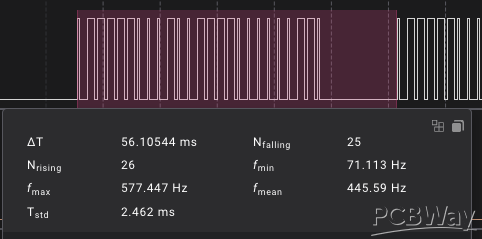
Prior to sending a message your microcontroller should first set values of signals D0 to D3. To send the message the microcontroller should energize VCC on the board for the duration of the message being sent. For the recommended oscillator values, this is about 60ms per message. You generally want to send at least 3 complete messages. In testing, the exact 180ms on-time wasn't long enough. 200ms on-time is the minimum.
To avoid parasitic power draw from the encoder chip on the digital lines, reset the microcontroller digital signals for D0 to D3 to 0 after sending the message.
void SendMessage(
uint8_t inPin)
{
digitalWrite(inPin, HIGH);
digitalWrite(Config::kSendPin, LOW); // LOW when kSendPin is connected to the gate of a P-Channel MOSFET turns it on.
//delay(180); not long enough
delay(200);
digitalWrite(Config::kSendPin, HIGH);
digitalWrite(inPin, LOW);
}
The board draws about 15mA @ 3v3, but there may be an initial surge. For this reason, if needed, use a P channel MOSFET with a 330uf or 470uf capacitor to avoid a mcu brownout (see example below.)


PT226x Remote v1.1
Project images are for reference only. Actual production is based on the manufacturing files on the project page.
Please review the designer's notes (e.g., PCB thickness) and select the appropriate options.
PCBWay is not responsible
for issues caused by unsuitable parameter selections.
For more important ordering information, please refer to
Read More


Raspberry Pi 5 7 Inch Touch Screen IPS 1024x600 HD LCD HDMI-compatible Display for RPI 4B 3B+ OPI 5 AIDA64 PC Secondary Screen(Without Speaker)
BUY NOW

- Comments(0)
- Likes(1)
More by Jonathan Mackey
-
 STM32 Audio Codec
This is an STM32 project that uses the TLV320AIC3204 codec.This STM32 project's PCB is essentially a...
STM32 Audio Codec
This is an STM32 project that uses the TLV320AIC3204 codec.This STM32 project's PCB is essentially a...
-
 OV5640 Camera v1.0
OV5640 Camera boardThis board uses 20 pin FFC connectors rather than the more common pin headers.Thi...
OV5640 Camera v1.0
OV5640 Camera boardThis board uses 20 pin FFC connectors rather than the more common pin headers.Thi...
-
 STM32F429 TFT DCMI v1.0
STM32F429 DCMI & FMCSupports a 3.5" 16 bit parallel TFT display via FMC, and 8 bit OV5640 camera...
STM32F429 TFT DCMI v1.0
STM32F429 DCMI & FMCSupports a 3.5" 16 bit parallel TFT display via FMC, and 8 bit OV5640 camera...
-
 STM32F103RE 3 Axis CNC v1
See my Instructable for a full implementation example here.All end stops, stepper driver fault lines...
STM32F103RE 3 Axis CNC v1
See my Instructable for a full implementation example here.All end stops, stepper driver fault lines...
-
 PT226x Remote v1.1
This is a remote encoder board that supports several versions of PT226x encoder chips in a number of...
PT226x Remote v1.1
This is a remote encoder board that supports several versions of PT226x encoder chips in a number of...
-
 Dust Collector Monitor v4
This is the 4th version of my dust collector monitor. See my instructable for a full description of ...
Dust Collector Monitor v4
This is the 4th version of my dust collector monitor. See my instructable for a full description of ...
-
 3.5 inch 480x320 TFT Display v1.1
Display sourceThis is a 3.5 inch ILI9488 320x480 display module tha...
3.5 inch 480x320 TFT Display v1.1
3.5 inch 480x320 TFT Display v1.1Display sourceThis is a 3.5 inch ILI9488 320x480 display module tha...
-
 4 inch 480x320 TFT Display v1.1
4.0 inch 480x320 TFT Display v1.1Display sourceThis is a 4 inch ILI9488 320x480 display module that ...
4 inch 480x320 TFT Display v1.1
4.0 inch 480x320 TFT Display v1.1Display sourceThis is a 4 inch ILI9488 320x480 display module that ...
-
 12 pin FFC Display Adaptor v1.0
This is a breadboard adapter for use with my boards that have a 12 pi...
12 pin FFC Display Adaptor v1.0
12 pin FFC Display Adaptor v1.0This is a breadboard adapter for use with my boards that have a 12 pi...
-
 ILI9488 Display Adapter v1.0
This adapter board converts the 14 pin header found on many display modu...
ILI9488 Display Adapter v1.0
ILI9488 Display Adapter v1.0This adapter board converts the 14 pin header found on many display modu...
-
 Heating System Monitor
This board is used to monitor the heating system in your home by reflecting the state of the alarm t...
Heating System Monitor
This board is used to monitor the heating system in your home by reflecting the state of the alarm t...
-
 4G LTE TempSensor v1.2 (SIM7000)
This board is used to monitor multiple temperature sensors and report out of range conditions to you...
4G LTE TempSensor v1.2 (SIM7000)
This board is used to monitor multiple temperature sensors and report out of range conditions to you...
-
 4 Port RJ11 4P4C v1.0
This board is part of a multi board project used to monitor multiple temperature sensors and report ...
4 Port RJ11 4P4C v1.0
This board is part of a multi board project used to monitor multiple temperature sensors and report ...
-
 BMP280 RFM69CW Remote
See my instructable for a full description of this board and the associated software.Part of my hiki...
BMP280 RFM69CW Remote
See my instructable for a full description of this board and the associated software.Part of my hiki...
-
 RFM69 3 Button Remote
See my instructable for a full description of this board and the associated software.Remote control ...
RFM69 3 Button Remote
See my instructable for a full description of this board and the associated software.Remote control ...
-
 Hiking Data Logger Using RFM69CW
This hiking data logger is used to record a hike’s location, start and end time, temperature, altitu...
Hiking Data Logger Using RFM69CW
This hiking data logger is used to record a hike’s location, start and end time, temperature, altitu...
-
 AVR SD Hex Loader ISP v1.4
This project is all about getting your compiled sketch onto your target board without the need to ha...
AVR SD Hex Loader ISP v1.4
This project is all about getting your compiled sketch onto your target board without the need to ha...
-
 Blast Gate Sensor
This is a blast gate sensor board. This uses a 49E Hall sensor to determine if a gate is open or clo...
Blast Gate Sensor
This is a blast gate sensor board. This uses a 49E Hall sensor to determine if a gate is open or clo...
-
Programmable Mist Maker - XIAO / QT PY Extension
1102 2 1 -
RadioHAT - Raspberry Pi radio development platform
916 0 2 -
-
-
-
-
ARPS-2 – Arduino-Compatible Robot Project Shield for Arduino UNO
3346 0 6 -
A Compact Charging Breakout Board For Waveshare ESP32-C3
3961 3 8 -
AI-driven LoRa & LLM-enabled Kiosk & Food Delivery System
4349 2 2


