


PIP WATCH Version 2
Greetings everyone and welcome back.
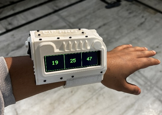
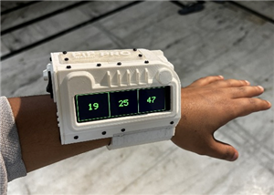
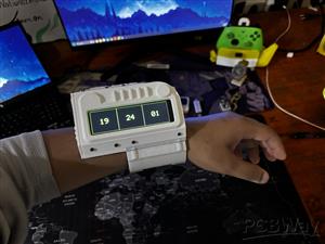
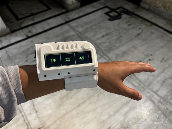
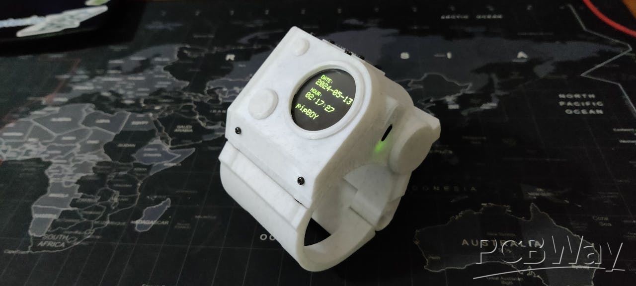
Meet PIP WATCH, a Pip-Boy-themed internet Watch that brings the retro-futuristic charm of the original device to your wrist, featuring the TTGO T DISPLAY ESP32 S3 LONG that has a super wide 640x180 Pixel screen that we are using as the main microcontroller and display for this project.

If you enjoy Fallout as much as I do, this PIP-WATCH is a great way to keep track of time in a Fallout style.
This is the Updated verssion of my previously created PIP WATCH V1 project that features a smaller GC9A01 Round display and a much smaller and different body than that of an actual PIP boy. In Version 2, we tried to model the device as close to its actual counterpart as possible, featuring the wide body design with a screen placed horizontally. The Clock funstuion remains the same in version 2; we are getting Time data from an NTP server and then it is being displayed on the screen.
In order to power our TTGO ESP32 Microcontroller, we have even integrated an inbuilt lithium cell.
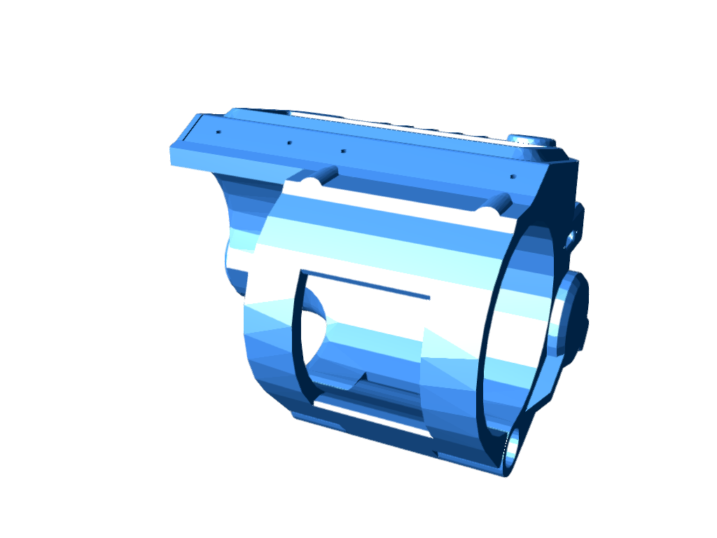
The code used for this project was adapted from the previous PIP WATCH project, the design was made in Fusion360, and this article explains how to make your own PIP Watch in a few simple steps.
MATERIAL REQUIRED
These are the components used in this build:
- TTGO T DISPLAY BOARD ESP32 S3 LONG
- Custom 3D printed Parts
- M2 Screws
- 14500 3.7V 600mAh Li-ion Cell
- Rocker Switch
PIP WATCH VERSION 1
I created a unique watch last year that was based on the Fallout video game series' PIP Boy. This PIP BOY Themed watch, also known as the PIP Watch, was an Internet watch that was driven by a FireBeetle ESP32 board with a round GC9A01 display.
In keeping with the Pipboy theme, PiPWatch receives time from an NTP server and shows the result in green on the round-oled screen.
You can check out more about this project from the below link.
https://www.hackster.io/Arnov_Sharma_makes/pip-watch-project-370245
WHAT IS PIPBOY?
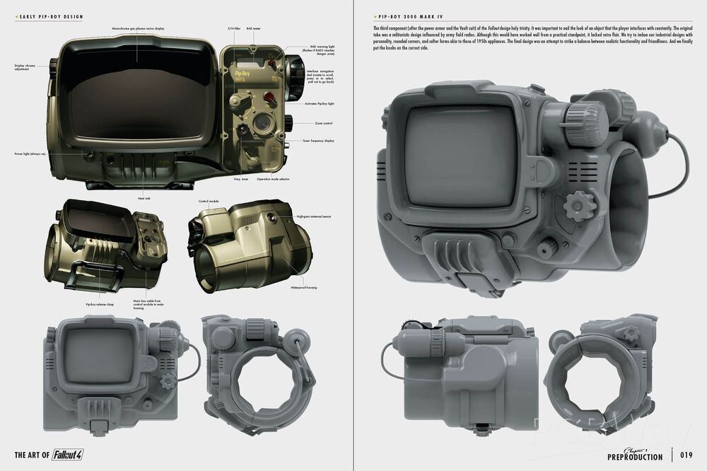

From the Fallout video games, the Pip-Boy is a fantastic small computer that is worn on the wrist. This retro-futuristic green screen on your wrist serves as your all-in-one assistant in the game, allowing you to track tasks, manage your inventory, check your health, and even browse maps.
It comes in a variety of models, each of which represents a specific Fallout timeline event or technological level. Consider the Pip-Boy 2000, a pre-war device manufactured prior to the Great War (2077). It was an early personal assistant with a monochrome display, a very limited interface, and basic stat tracking.
It was more of a lore reference and was hardly ever visible in gameplay.
Then came the Pip-Boy 2000 Mark II, a little better version of the Mark I with more memory and processing, a more durable housing, and a slightly better display. It was still a pre-war device.
The Pip-Boy 3000 from Fallout 3 and New Vegas came next. It included a color screen and tracked statistics like radiation, HP, inventory, map, and quest log, and it even included a flashlight, radio, and holotape reader.
Other versions include the Pip-Boy 1.0/1.1, the Pip-Boy 4000 series, the Pip-Boy 3000 Mark IV, and others.
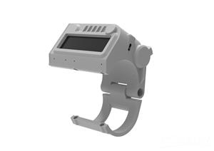
DESIGN VERSION 2
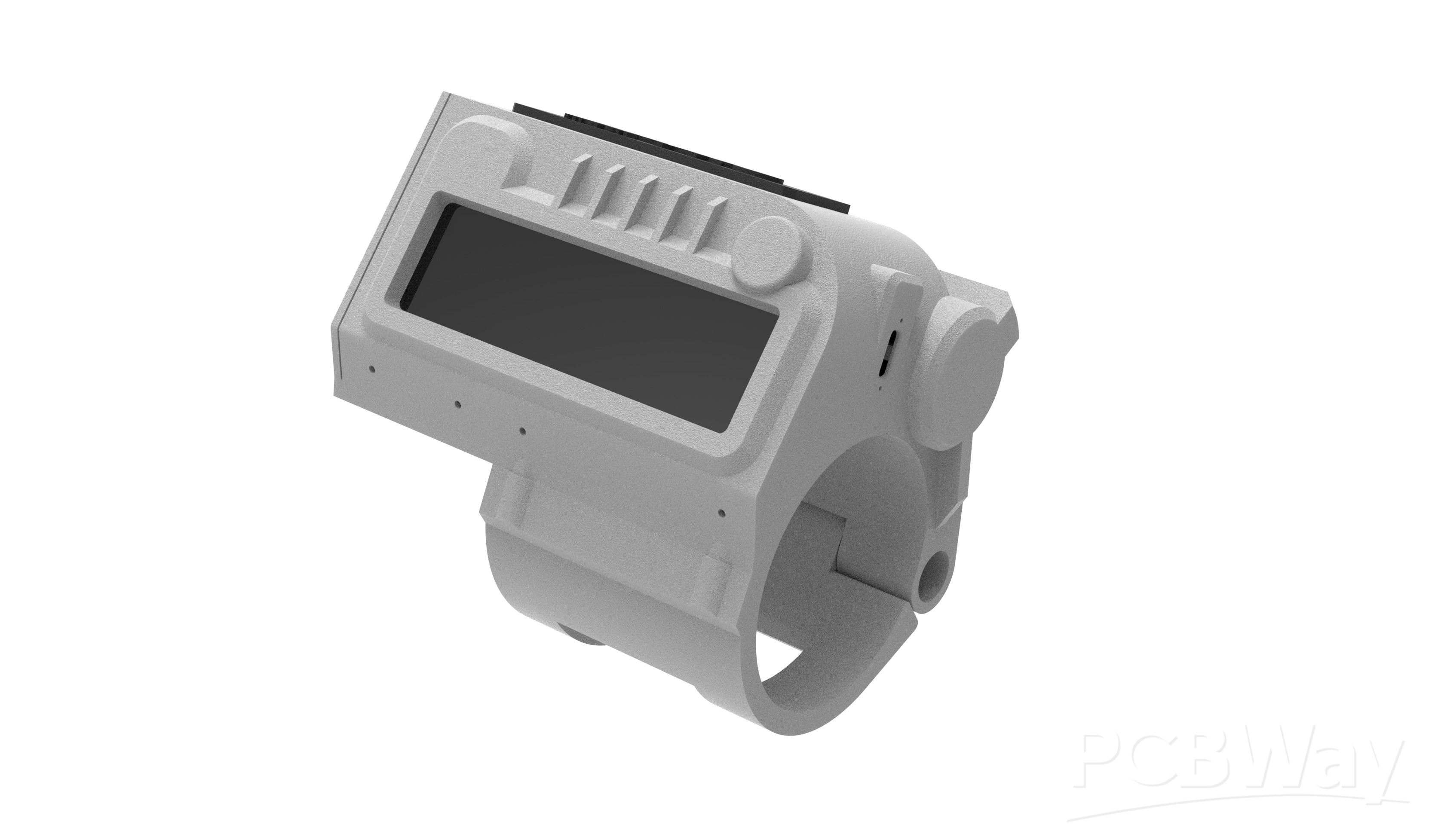


The 3D model was the first step in this project, and our objective was to reuse parts from the previous project.
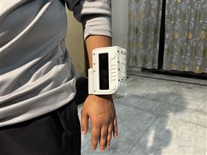
We decide to retain the wrist clamp, which is attached to the main body and pivots on a hinge. In order to keep the hinge clamp part of the watch attached to the body, super magnets are attached to the inside of the clamp and body. The hinge part of the watch is secured in place by these magnets. It can be worn by applying some force to the magnet joints, which will open the clamp and allow the user to put the watch on their wrist.
To make it easier to mount the TTGO Display horizontally, we simply modeled a new holder around the main body while maintaining the same structure. Additionally modeled was the new screen holder part that secures the display.
A rocker switch that will be used to turn the setup ON or OFF has been added to the lid part, just like in the previous version.
To show that this is a newer version of the PIP WATCH PROJECT SERIES, there is now a nametag that says PIP WATCH PRO.
Once the 3D model was finished, we exported the mesh files and used our ENDER 3 to print all of the parts in white PLA.
TTGO T-DISPLAY ESP32 S3 LONG
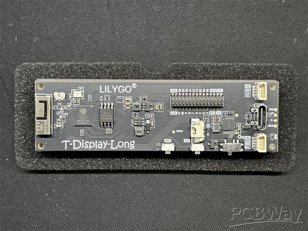
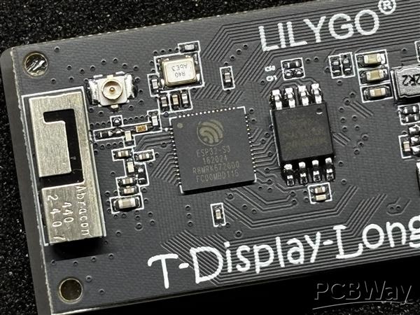
The Liligo TTGO T-Display S3 Long, which is the brain of this project, is powered by an ESP32-S3R8 dual-core LX7 microprocessor and provides strong performance for demanding applications.
It is perfect for connectivity projects because it has Bluetooth Mesh, BLE 5, and Wi-Fi 802.11. It can easily handle complex graphics and multitasking thanks to its 16 MB of flash and 8 MB of PSRAM.
Its most notable feature is the 3.4-inch capacitive touch TFT LCD, which uses a QSPI interface and has a 180 × 640 RGB pixel resolution, making it ideal for touch-enabled, long displays.
I think LILIGO should have created a proper wiki to make this amazing hardware user-friendly because I had a very difficult time figuring out exactly how we can use this display and had to rely on the Volos Project Video about the TTGO T DISPLAY S3 LONG Board. The information on this display is very limited; by limited, I mean the documentation is very weak. I suggest you should watch Volos Video on the board because it goes into great detail regarding essentially every aspect of this display.
PCBWAY GIFTSHOP
As for sourcing the Liligo TTGO T DISPLAY S3 we used in this project, we got them from PCBWAY's Giftshop.
PCBWAY gift shop is an online marketplace where you can get a variety of electronics modules and boards for their genuine price, or you could use the PCBWAY currency, which is called beans.
You get beans after ordering something from PCBWAY as reward points, or you can also get them by posting any project in the PCBWAY community.
Over the past ten years, PCBWay has distinguished themselves by providing outstanding PCB manufacturing and assembly services, becoming a trusted partner for countless engineers and designers worldwide.
You guys can check out PCBWAY if you want great PCB service at an affordable rate.
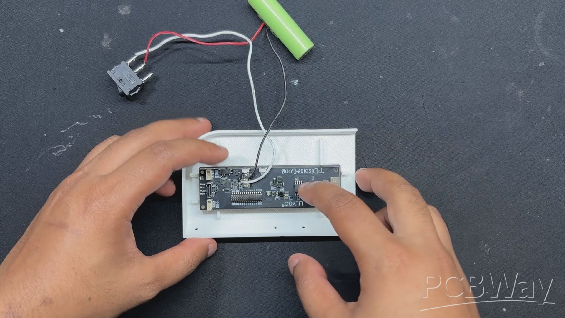
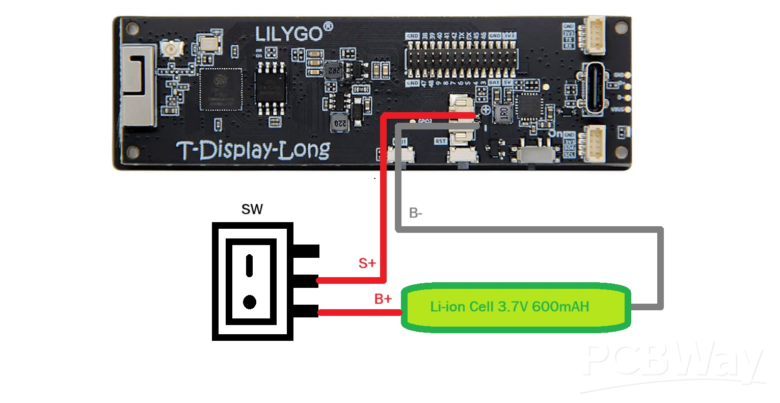
WIRING PROCESS

- The first step in the entire process is to connect our power source, which is a 14500 3.7V 600mAh Li-ion cell with a PCM.
- The PCM has a DW01 Circuit that gives the cell low and high cut features, which are necessary for charging and discharging the cell correctly without causing a blast.
- First, we connected the lithium cell's positive and negative terminals to the TTGO Board's positive and negative battery terminals.
- Next, we attached a switch between the TTGo board and the battery connections. We soldered one end of the positive wire from the battery to the switch's NO terminal, and the switch's NC terminal is linked to the TTGO battery terminal's positive terminal. To break power between the battery and the TTGO board, we installed this switch between them.
MAIN CODE

This was the code we used in this project, and it’s definitely not the simplest one. First, I want to give a shout-out to the absolute legend nikthefix—thanks to the repository he made for this display, we were able to work with it without relying on the code provided by TTGO.
We mostly followed the code structure from nikthefix’s repo and kept the AXS15231B header and implementation files, which handle communication with the display hardware, including sending pixels, drawing shapes, and initializing the screen.
#include "AXS15231B.h" #include "pins_config.h" #include <WiFi.h> #include <NTPClient.h> #include <WiFiUdp.h> #define SCREEN_W 640 #define SCREEN_H 180 uint16_t frameBuffer[SCREEN_W * SCREEN_H]; #define RECT_WIDTH (SCREEN_W / 3) #define RECT_HEIGHT SCREEN_H int scale = 6; // bigger numbers #define GREEN 0xE007 #define BLACK 0x0000 const uint8_t font5x7[][5] = { {0x3E,0x51,0x49,0x45,0x3E}, // 0 {0x00,0x42,0x7F,0x40,0x00}, // 1 {0x42,0x61,0x51,0x49,0x46}, // 2 {0x21,0x41,0x45,0x4B,0x31}, // 3 {0x18,0x14,0x12,0x7F,0x10}, // 4 {0x27,0x45,0x45,0x45,0x39}, // 5 {0x3C,0x4A,0x49,0x49,0x30}, // 6 {0x01,0x71,0x09,0x05,0x03}, // 7 {0x36,0x49,0x49,0x49,0x36}, // 8 {0x06,0x49,0x49,0x29,0x1E}, // 9 }; // WiFi credentials const char* ssid = "add your SSID"; const char* password = "add your PASSWORD"; // NTP Client WiFiUDP ntpUDP; NTPClient timeClient(ntpUDP, "pool.ntp.org", 19800); // IST void drawCharScaled(uint16_t *buf, int w, int x, int y, char c, uint16_t color, uint16_t bg, int s){ if(c<'0' || c>'9') return; int idx = c - '0'; for(int col=0; col<5; col++){ uint8_t line = font5x7[idx][col]; for(int row=0; row<7; row++){ uint16_t px_color = (line & (1<<row)) ? color : bg; for(int dx=0; dx<s; dx++){ for(int dy=0; dy<s; dy++){ int px = x + col*s + dx; int py = y + row*s + dy; if(px<w && py<SCREEN_H) buf[py*w + px] = px_color; } } } } } void drawTextScaled(uint16_t *buf, int w, int x, int y, const char* text, uint16_t color, uint16_t bg, int s){ while(*text){ drawCharScaled(buf, w, x, y, *text, color, bg, s); x += (5+1)*s; text++; } } void fillRectBuffer(uint16_t *buf, int w, int x, int y, int rect_w, int rect_h, uint16_t color){ for(int j=0;j<rect_h;j++) for(int i=0;i<rect_w;i++) buf[(y+j)*w + (x+i)] = color; } void drawRectBuffer(uint16_t *buf, int w, int x, int y, int rect_w, int rect_h, uint16_t color){ for(int i=0;i<rect_w;i++){ buf[y*w + x + i] = color; buf[(y+rect_h-1)*w + x + i] = color; } for(int j=0;j<rect_h;j++){ buf[(y+j)*w + x] = color; buf[(y+j)*w + x + rect_w-1] = color; } } void setup() { pinMode(TFT_BL, OUTPUT); digitalWrite(TFT_BL, HIGH); axs15231_init(); Serial.begin(115200); WiFi.begin(ssid, password); Serial.print("Connecting to WiFi"); while(WiFi.status() != WL_CONNECTED){ delay(500); Serial.print("."); } Serial.println("\nWiFi connected"); timeClient.begin(); // Draw static rectangles once fillRectBuffer(frameBuffer, SCREEN_W, 0, 0, SCREEN_W, SCREEN_H, BLACK); drawRectBuffer(frameBuffer, SCREEN_W, 0, 0, RECT_WIDTH, RECT_HEIGHT, GREEN); drawRectBuffer(frameBuffer, SCREEN_W, RECT_WIDTH, 0, RECT_WIDTH, RECT_HEIGHT, GREEN); drawRectBuffer(frameBuffer, SCREEN_W, RECT_WIDTH*2, 0, RECT_WIDTH, RECT_HEIGHT, GREEN); lcd_PushColors_rotated_90(0,0,SCREEN_W,SCREEN_H, frameBuffer); } -1; void loop(){ if(timeClient.update()){ int hours = timeClient.getHours(); int minutes = timeClient.getMinutes(); int seconds = timeClient.getSeconds(); char buf[3]; int y_center = (SCREEN_H - 7*scale) / 2; // Only update digits that changedif(hours != prevHours){ sprintf(buf,"%02d", hours); fillRectBuffer(frameBuffer, SCREEN_W, 0, y_center, RECT_WIDTH, 7*scale, BLACK); drawTextScaled(frameBuffer, SCREEN_W, RECT_WIDTH/2 - scale*6, y_center, buf, GREEN, BLACK, scale); prevHours = hours; } if(minutes != prevMinutes){ sprintf(buf,"%02d", minutes); fillRectBuffer(frameBuffer, SCREEN_W, RECT_WIDTH, y_center, RECT_WIDTH, 7*scale, BLACK); drawTextScaled(frameBuffer, SCREEN_W, RECT_WIDTH + RECT_WIDTH/2 - scale*6, y_center, buf, GREEN, BLACK, scale); prevMinutes = minutes; } if(seconds != prevSeconds){ sprintf(buf,"%02d", seconds); fillRectBuffer(frameBuffer, SCREEN_W, RECT_WIDTH*2, y_center, RECT_WIDTH, 7*scale, BLACK); drawTextScaled(frameBuffer, SCREEN_W, RECT_WIDTH*2 + RECT_WIDTH/2 - scale*6, y_center, buf, GREEN, BLACK, scale); prevSeconds = seconds; } lcd_PushColors_rotated_90(0,0,SCREEN_W,SCREEN_H, frameBuffer); } }
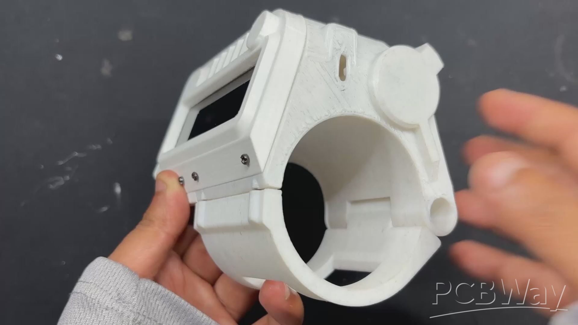
BASE FRAME ASSEMBLY PROCESS
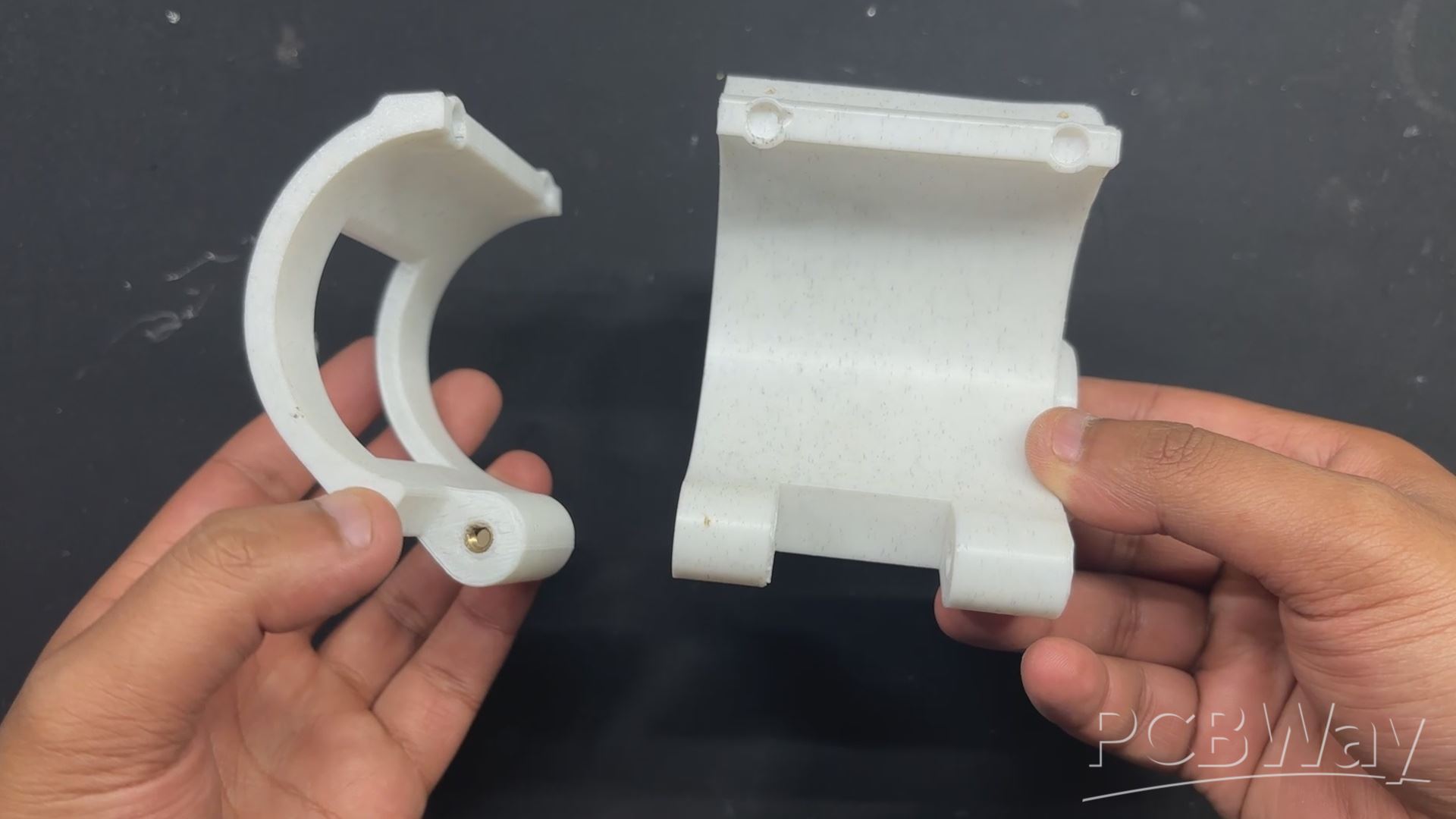
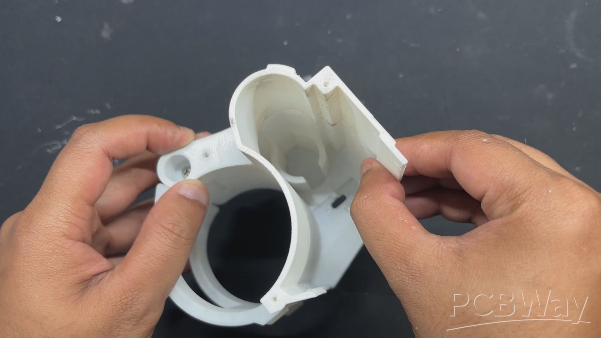
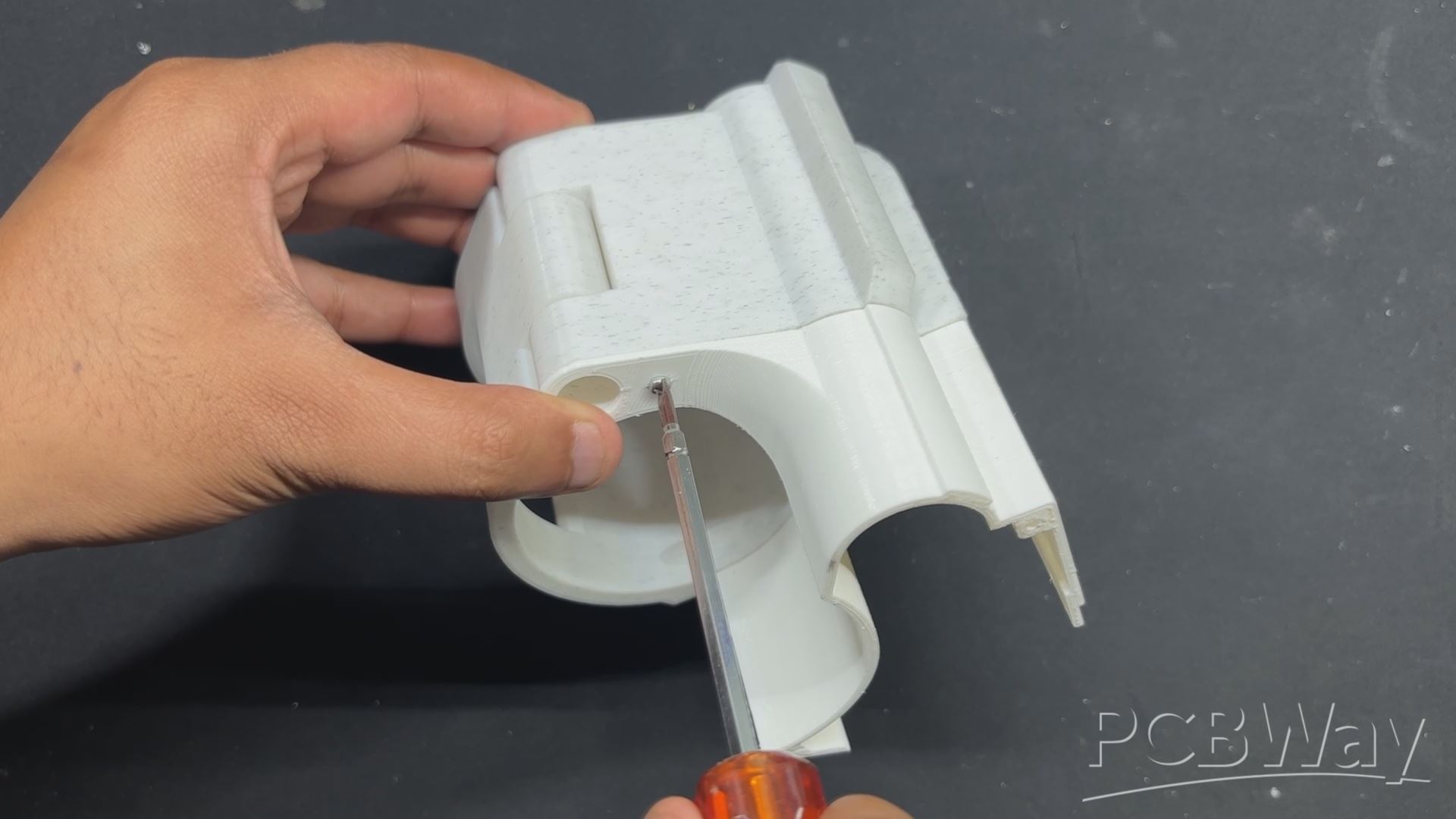
- We now start the project's Body build, which starts with setting up the project's Base. We fasten the main body with the lower clamp part using M2.5 bolts.
- The extension part is then positioned over one side of the main body, its mounting hole is aligned with the main body, and an M2 screw is used to fasten them together.
- The nameplate, which essentially holds the main body and extension section together with four screws positioned in corners, is installed in place once the extension part has been placed.
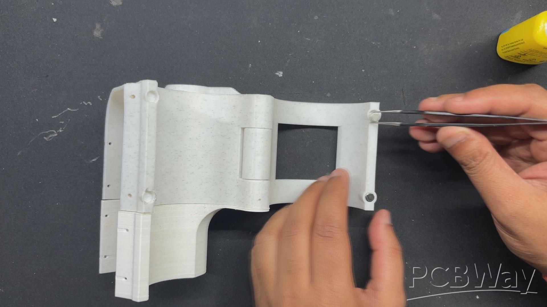
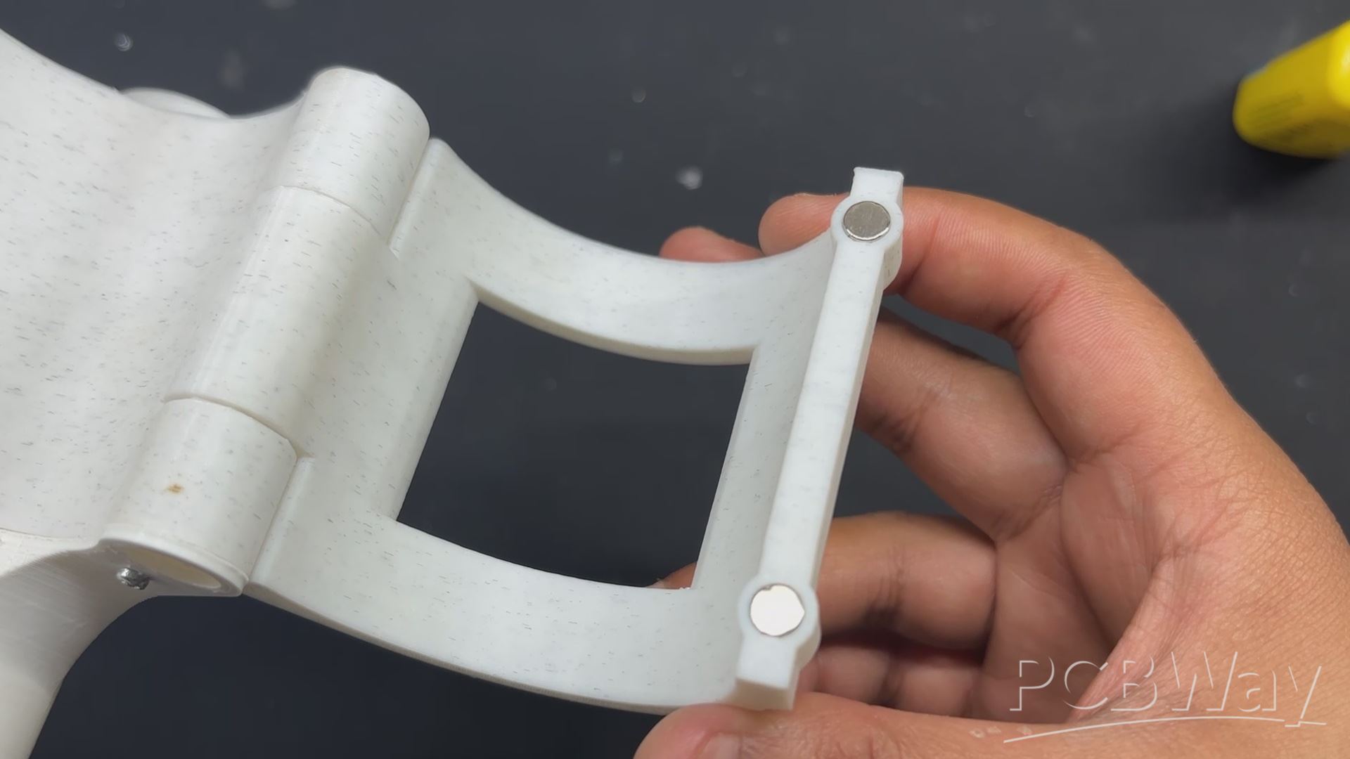
- Next, we add tiny magnets with a diameter of 5 mm to the main body and clamp part. Our first step is to apply a drop of super glue to the magnet's clamp mounting place. This will ensure that the magnet remains in place permanently.
- Similar to this, we add magnets to the main body by following the same process, but we make sure to face them in the correct direction since this section employs two magnets to create a magnetic lock, and magnetism is crucial in this situation; utilizing the same poles on the same side will break the entire system.
SCREEN HOLDER & DISPLAY ASSEMBLY
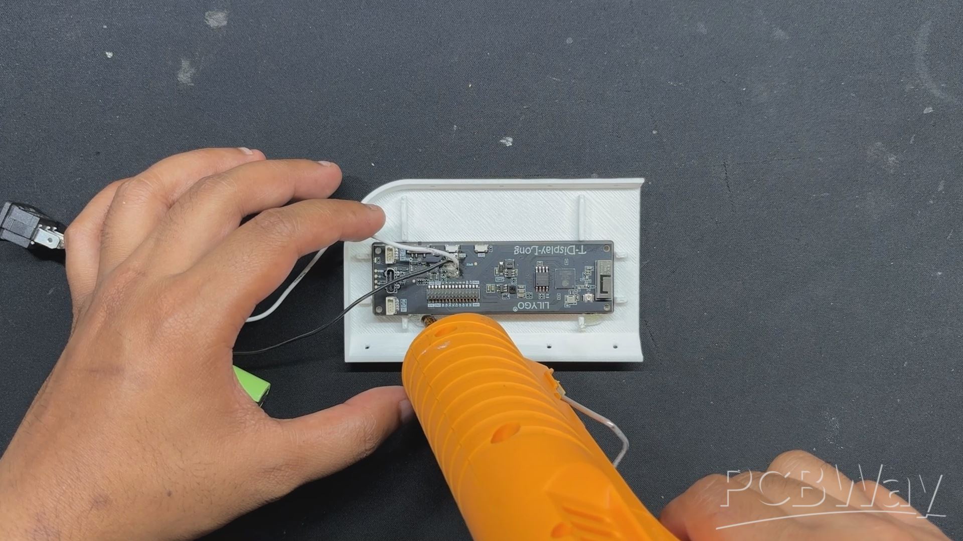
Now that the TTGO Display is positioned over the screen holder, the screen side of the TTGO T Display board is facing out.
We apply hot glue to the entire board's perimeter to keep it in place. This will create a connection between the display and the screen holder.
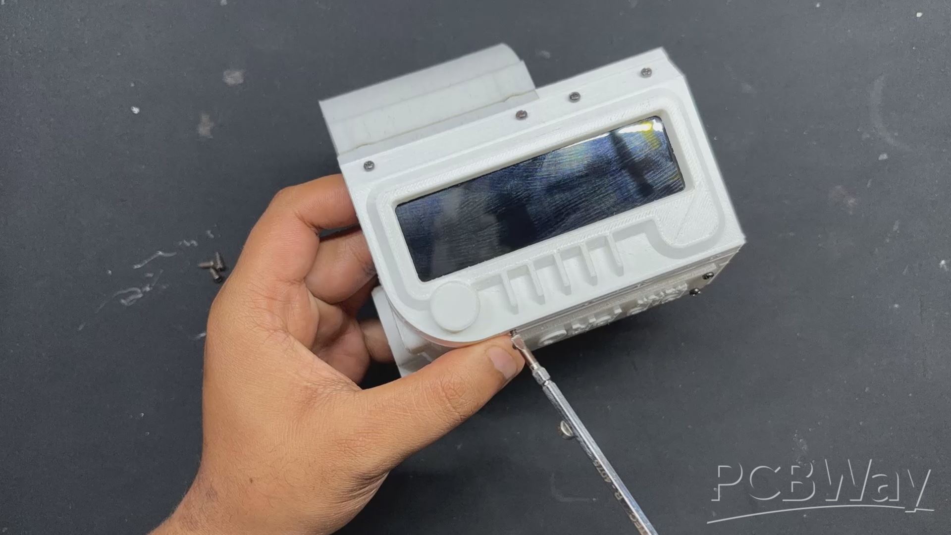
LID ASSEMBLY
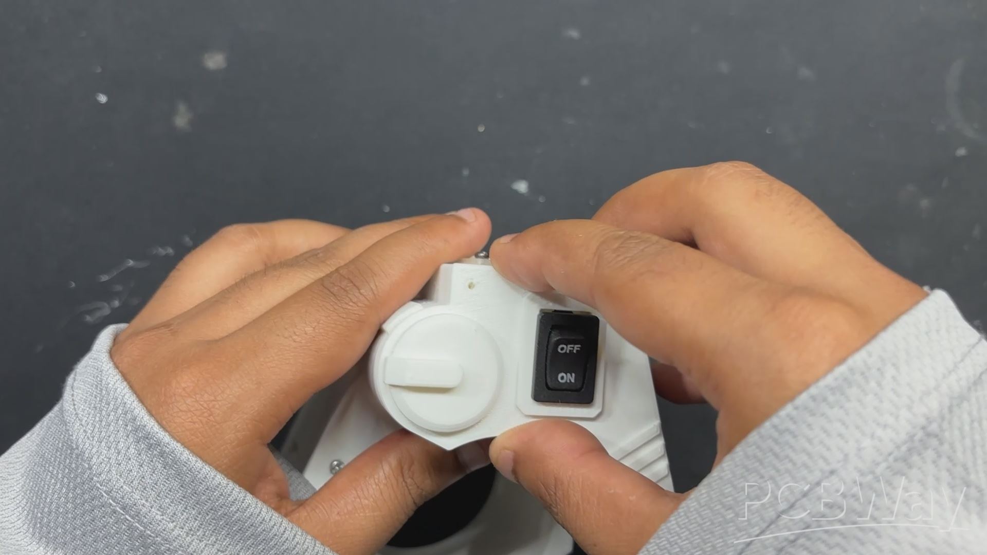
- The next step was the lid assembly, which starts with desoldering the wires from the rocker switch so that we can insert the rocker into the opening on the lid part. After positioning the rocker switch, we reattach its wires.
- After that, the lid is pushed into place and fastened with two M2 screws to the extension part.
CUSHION SUPPORT
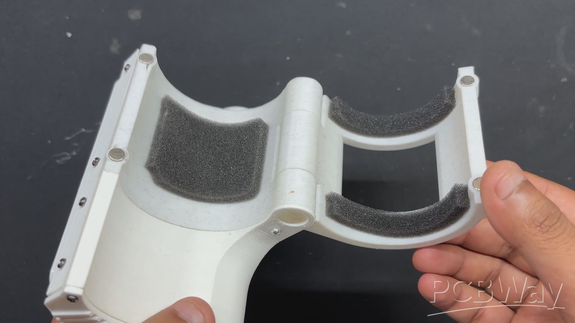
- The cushion support on the inside of the hand clamp is one of the last finishing touches that we need to add to this project, which is almost finished. This thin foam sheet was included with the TTGO T Display package; we will cut it into pieces and place it inside the clamp part.
- We completed the assembly process by first applying two long foam cutout pieces to the clamp part using hot glue, followed by the addition of a rectangular foam piece to the main body.
RESULT & CONCLUSION

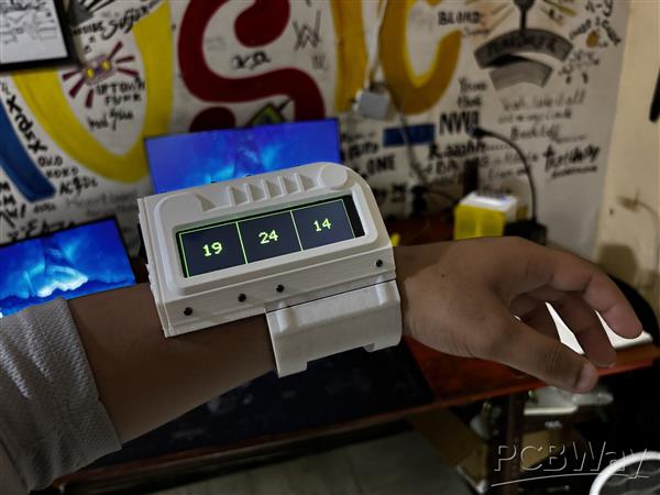
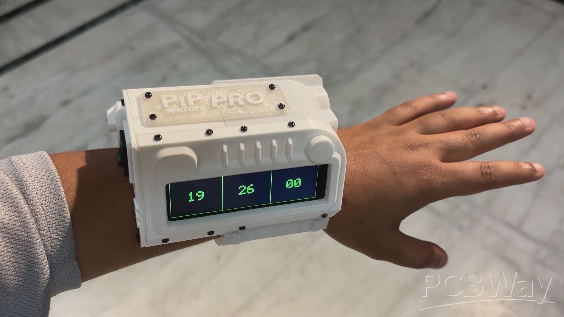
This small project Resulted into a fully functional PIP WATCH PROJECT, a PIP Boy-inspired watch built from scratch that connects to the internet using an ESP32 and an NTP server to retrieve time data, which is then displayed on a Liligo TTGO T-DISPLAY S3 LONG.
In order to wear this device, we have to first fully open the clamp, place our hand between the clamp and the main body, then use the super magnets to close the clamp part, latching the wristwatch.
If you enjoy Fallout as much as I do, this PIPWATCH is a great way to keep track of time in a Fallout style. I personally like Fallout: New Vegas over Fallout 4, but that's just my take on things. I also thought the new TV show did a fantastic job of capturing the essence of the game.
Overall, this PIP-WATCH has been completed, but I would like to get back to it soon to continue working on the clock's graphical design. Due to an issue I encountered throughout the code process, I created a basic clock interface with borders between HH, MM, and SS. this may be further improved into a matching aesthetic of an actual pip boy, furthermore i will make a separate article about performing a Paint Job on this project to give it a post-apocalyptic military look.
I will be addressing all of these topics in the upcoming updates. You can download and create your own PIP WATCH using the code, connection diagram, and CAD files that are all attached.
I appreciate you getting this far, and I'll be back soon with a new project.
Peace.
#include "AXS15231B.h"
#include "pins_config.h"

#include <WiFi.h>
#include <NTPClient.h>
#include <WiFiUdp.h>

#define SCREEN_W 640
#define SCREEN_H 180
uint16_t frameBuffer[SCREEN_W * SCREEN_H];

#define RECT_WIDTH  (SCREEN_W / 3)
#define RECT_HEIGHT SCREEN_H

int scale = 6;  // bigger numbers

#define GREEN 0xE007
#define BLACK 0x0000

const uint8_t font5x7[][5] = {
  {0x3E,0x51,0x49,0x45,0x3E}, // 0
  {0x00,0x42,0x7F,0x40,0x00}, // 1
  {0x42,0x61,0x51,0x49,0x46}, // 2
  {0x21,0x41,0x45,0x4B,0x31}, // 3
  {0x18,0x14,0x12,0x7F,0x10}, // 4
  {0x27,0x45,0x45,0x45,0x39}, // 5
  {0x3C,0x4A,0x49,0x49,0x30}, // 6
  {0x01,0x71,0x09,0x05,0x03}, // 7
  {0x36,0x49,0x49,0x49,0x36}, // 8
  {0x06,0x49,0x49,0x29,0x1E}, // 9
};

// WiFi credentials
const char* ssid = "add your SSID";
const char* password = "add your PASSWORD";

// NTP Client
WiFiUDP ntpUDP;
NTPClient timeClient(ntpUDP, "pool.ntp.org", 19800); // IST

void drawCharScaled(uint16_t *buf, int w, int x, int y, char c, uint16_t color, uint16_t bg, int s){
    if(c<'0' || c>'9') return;
    int idx = c - '0';
    for(int col=0; col<5; col++){
        uint8_t line = font5x7[idx][col];
        for(int row=0; row<7; row++){
            uint16_t px_color = (line & (1<<row)) ? color : bg;
            for(int dx=0; dx<s; dx++){
                for(int dy=0; dy<s; dy++){
                    int px = x + col*s + dx;
                    int py = y + row*s + dy;
                    if(px<w && py<SCREEN_H) buf[py*w + px] = px_color;
                }
            }
        }
    }
}

void drawTextScaled(uint16_t *buf, int w, int x, int y, const char* text, uint16_t color, uint16_t bg, int s){
    while(*text){
        drawCharScaled(buf, w, x, y, *text, color, bg, s);
        x += (5+1)*s;
        text++;
    }
}

void fillRectBuffer(uint16_t *buf, int w, int x, int y, int rect_w, int rect_h, uint16_t color){
    for(int j=0;j<rect_h;j++)
        for(int i=0;i<rect_w;i++)
            buf[(y+j)*w + (x+i)] = color;
}

void drawRectBuffer(uint16_t *buf, int w, int x, int y, int rect_w, int rect_h, uint16_t color){
    for(int i=0;i<rect_w;i++){
        buf[y*w + x + i] = color;
        buf[(y+rect_h-1)*w + x + i] = color;
    }
    for(int j=0;j<rect_h;j++){
        buf[(y+j)*w + x] = color;
        buf[(y+j)*w + x + rect_w-1] = color;
    }
}

void setup() {
    pinMode(TFT_BL, OUTPUT);
    digitalWrite(TFT_BL, HIGH);
    axs15231_init();

    Serial.begin(115200);
    WiFi.begin(ssid, password);
    Serial.print("Connecting to WiFi");
    while(WiFi.status() != WL_CONNECTED){
        delay(500);
        Serial.print(".");
    }
    Serial.println("\nWiFi connected");

    timeClient.begin();

    // Draw static rectangles once
    fillRectBuffer(frameBuffer, SCREEN_W, 0, 0, SCREEN_W, SCREEN_H, BLACK);
    drawRectBuffer(frameBuffer, SCREEN_W, 0, 0, RECT_WIDTH, RECT_HEIGHT, GREEN);
    drawRectBuffer(frameBuffer, SCREEN_W, RECT_WIDTH, 0, RECT_WIDTH, RECT_HEIGHT, GREEN);
    drawRectBuffer(frameBuffer, SCREEN_W, RECT_WIDTH*2, 0, RECT_WIDTH, RECT_HEIGHT, GREEN);
    lcd_PushColors_rotated_90(0,0,SCREEN_W,SCREEN_H, frameBuffer);
}

int prevHours=-1, prevMinutes=-1, prevSeconds=-1;

void loop(){
    if(timeClient.update()){
        int hours = timeClient.getHours();
        int minutes = timeClient.getMinutes();
        int seconds = timeClient.getSeconds();

        char buf[3];
        int y_center = (SCREEN_H - 7*scale) / 2;

        // Only update digits that changed
        if(hours != prevHours){
            sprintf(buf,"%02d", hours);
            fillRectBuffer(frameBuffer, SCREEN_W, 0, y_center, RECT_WIDTH, 7*scale, BLACK);
            drawTextScaled(frameBuffer, SCREEN_W, RECT_WIDTH/2 - scale*6, y_center, buf, GREEN, BLACK, scale);
            prevHours = hours;
        }

        if(minutes != prevMinutes){
            sprintf(buf,"%02d", minutes);
            fillRectBuffer(frameBuffer, SCREEN_W, RECT_WIDTH, y_center, RECT_WIDTH, 7*scale, BLACK);
            drawTextScaled(frameBuffer, SCREEN_W, RECT_WIDTH + RECT_WIDTH/2 - scale*6, y_center, buf, GREEN, BLACK, scale);
            prevMinutes = minutes;
        }

        if(seconds != prevSeconds){
            sprintf(buf,"%02d", seconds);
            fillRectBuffer(frameBuffer, SCREEN_W, RECT_WIDTH*2, y_center, RECT_WIDTH, 7*scale, BLACK);
            drawTextScaled(frameBuffer, SCREEN_W, RECT_WIDTH*2 + RECT_WIDTH/2 - scale*6, y_center, buf, GREEN, BLACK, scale);
            prevSeconds = seconds;
        }

        lcd_PushColors_rotated_90(0,0,SCREEN_W,SCREEN_H, frameBuffer);
    }
}
PIP WATCH Version 2
Project images are for reference only. Actual production is based on the manufacturing files on the project page.
Please review the designer's notes (e.g., PCB thickness) and select the appropriate options.
PCBWay is not responsible
for issues caused by unsuitable parameter selections.
For more important ordering information, please refer to
Read More


Raspberry Pi 5 7 Inch Touch Screen IPS 1024x600 HD LCD HDMI-compatible Display for RPI 4B 3B+ OPI 5 AIDA64 PC Secondary Screen(Without Speaker)
BUY NOW


- Comments(0)
- Likes(3)
More by Arnov Arnov sharma
-
 DIY XBOX Controller
Greetings everyone, and welcome back. Here's something fun and custom.This is my version of an Xbox ...
DIY XBOX Controller
Greetings everyone, and welcome back. Here's something fun and custom.This is my version of an Xbox ...
-
 Pocket SNES
Greetings everyone, and welcome back! Today, I’ve got something fun and tiny to share—the Pocket SNE...
Pocket SNES
Greetings everyone, and welcome back! Today, I’ve got something fun and tiny to share—the Pocket SNE...
-
 Batocera Arcade Box
Greetings everyone and welcome back, Here's something. Fun and nostalgic. Right now, we are using ou...
Batocera Arcade Box
Greetings everyone and welcome back, Here's something. Fun and nostalgic. Right now, we are using ou...
-
 64x32 Matrix Panel Setup with PICO 2
Greetings everyone and welcome back.So here's something fun and useful: a Raspberry Pi Pico 2-powere...
64x32 Matrix Panel Setup with PICO 2
Greetings everyone and welcome back.So here's something fun and useful: a Raspberry Pi Pico 2-powere...
-
 Portable Air Quality Meter
Hello everyone, and welcome back! Today, I have something incredibly useful for you—a Portable Air Q...
Portable Air Quality Meter
Hello everyone, and welcome back! Today, I have something incredibly useful for you—a Portable Air Q...
-
 WALKPi PCB Version
Greetings everyone and welcome back, This is the WalkPi, a homebrew audio player that plays music fr...
WALKPi PCB Version
Greetings everyone and welcome back, This is the WalkPi, a homebrew audio player that plays music fr...
-
 Delete Button XL
Greetings everyone and welcome back, and here's something fun and useful.In essence, the Delete Butt...
Delete Button XL
Greetings everyone and welcome back, and here's something fun and useful.In essence, the Delete Butt...
-
 Arduino Retro Game Controller
Greetings everyone and welcome back. Here's something fun.The Arduino Retro Game Controller was buil...
Arduino Retro Game Controller
Greetings everyone and welcome back. Here's something fun.The Arduino Retro Game Controller was buil...
-
 Super Power Buck Converter
Greetings everyone and welcome back!Here's something powerful, The SUPER POWER BUCK CONVERTER BOARD ...
Super Power Buck Converter
Greetings everyone and welcome back!Here's something powerful, The SUPER POWER BUCK CONVERTER BOARD ...
-
 Pocket Temp Meter
Greetings and welcome back.So here's something portable and useful: the Pocket TEMP Meter project.As...
Pocket Temp Meter
Greetings and welcome back.So here's something portable and useful: the Pocket TEMP Meter project.As...
-
 Pico Powered DC Fan Driver
Hello everyone and welcome back.So here's something cool: a 5V to 12V DC motor driver based around a...
Pico Powered DC Fan Driver
Hello everyone and welcome back.So here's something cool: a 5V to 12V DC motor driver based around a...
-
 Mini Solar Light Project with a Twist
Greetings.This is the Cube Light, a Small and compact cube-shaped emergency solar light that boasts ...
Mini Solar Light Project with a Twist
Greetings.This is the Cube Light, a Small and compact cube-shaped emergency solar light that boasts ...
-
 PALPi V5 Handheld Retro Game Console
Hey, Guys what's up?So this is PALPi which is a Raspberry Pi Zero W Based Handheld Retro Game Consol...
PALPi V5 Handheld Retro Game Console
Hey, Guys what's up?So this is PALPi which is a Raspberry Pi Zero W Based Handheld Retro Game Consol...
-
 DIY Thermometer with TTGO T Display and DS18B20
Greetings.So this is the DIY Thermometer made entirely from scratch using a TTGO T display board and...
DIY Thermometer with TTGO T Display and DS18B20
Greetings.So this is the DIY Thermometer made entirely from scratch using a TTGO T display board and...
-
 Motion Trigger Circuit with and without Microcontroller
GreetingsHere's a tutorial on how to use an HC-SR505 PIR Module with and without a microcontroller t...
Motion Trigger Circuit with and without Microcontroller
GreetingsHere's a tutorial on how to use an HC-SR505 PIR Module with and without a microcontroller t...
-
 Motor Driver Board Atmega328PU and HC01
Hey, what's up folks here's something super cool and useful if you're making a basic Robot Setup, A ...
Motor Driver Board Atmega328PU and HC01
Hey, what's up folks here's something super cool and useful if you're making a basic Robot Setup, A ...
-
 Power Block
Hey Everyone what's up!So this is Power block, a DIY UPS that can be used to power a bunch of 5V Ope...
Power Block
Hey Everyone what's up!So this is Power block, a DIY UPS that can be used to power a bunch of 5V Ope...
-
 Goku PCB Badge V2
Hey everyone what's up!So here's something SUPER cool, A PCB Board themed after Goku from Dragon Bal...
Goku PCB Badge V2
Hey everyone what's up!So here's something SUPER cool, A PCB Board themed after Goku from Dragon Bal...
-
Programmable Mist Maker - XIAO / QT PY Extension
1102 2 1 -
RadioHAT - Raspberry Pi radio development platform
916 0 2 -
-
-
-
-
ARPS-2 – Arduino-Compatible Robot Project Shield for Arduino UNO
3346 0 6 -
A Compact Charging Breakout Board For Waveshare ESP32-C3
3961 3 8 -
AI-driven LoRa & LLM-enabled Kiosk & Food Delivery System
4349 2 2


