


PARALLEL PC- Wood Edition
Greetings, everyone, and welcome back. This one’s a big build—meet the Parallel PC.
Parallel PC is a DIY all-in-one computer featuring a custom body made from wooden panels and 3D-printed parts, built around a 15-inch LED display. What makes it special is that it houses not one but two different single-board computers. One is the ARM-based Raspberry Pi Compute Module 5 with its official evaluation board, and the other is an x86-based LattePanda MU.
The idea behind this project was to take one of my previous builds—the WoodWorks Fusion PC—and transform it into a dual-compute system. With the press of a single button, the active computer connected to the main display can be switched instantly. If you want to work on Raspberry Pi projects, you switch to the Pi. If you need an x86 environment to run Windows or, in our case, Bazzite, you switch over to the LattePanda. One enclosure, one monitor, two completely different computing platforms.
Built using a combination of wooden panels and custom 3D-printed parts, this project is the starting point of the Parallel PC series. The goal is to keep evolving this enclosure—retrofitting new hardware, adding more single-board computers, and experimenting with different ideas over time.
This article covers the complete build process of the Parallel PC, from design to final assembly. Let’s get started with the build.
MATERIALS REQUIRED
These were the materials we used in this build:
- Custom PCBs (provided by PCBWAY)
- Woodwork Fusion PC Body (that includes all the wooden parts)
- Raspberry Pi CM5 with expansion board
- Type C to C PD Cable
- Lattepanda MU with Full Evaluation Board
- HDMI Splitter
- 15-inch LED Display along with its Driver (Salvaged from a new monitor)
- 12V 5A Mini SMPS
- Wood screws M4
- 3D-printed parts
- PD Buck Converter
- HDMI CABLE 0.5 METER
- HDMI BREAKOUT BOARD WITH FLAT CABLE
- M2 SCREWS
Woodwork Fusion PC
The original WoodWorks Fusion PCwas a custom all-in-one computer built from scratch using a combination of wood and 3D-printed parts, inspired by CyberDesk-style aesthetics.
The goal was not performance but form—creating a visually striking enclosure around deliberately outdated hardware, basically a potato PC.
At its core, the system used a 4th-generation Intel i3 desktop CPU mounted on a Mini-ATX motherboard, paired with 12 GB of DDR3 RAM and a GT 710 GPU. While the hardware was clearly obsolete, the enclosure was designed to be modular, allowing components to be easily upgraded in the future without changing the overall structure.
The body was primarily constructed from plywood, chosen for its strength and ease of fabrication. 3D-printed L-brackets were used to join panels together, forming a rigid cuboid enclosure capable of housing the motherboard, power supply, storage drives, and display.
DISASSEMBLY

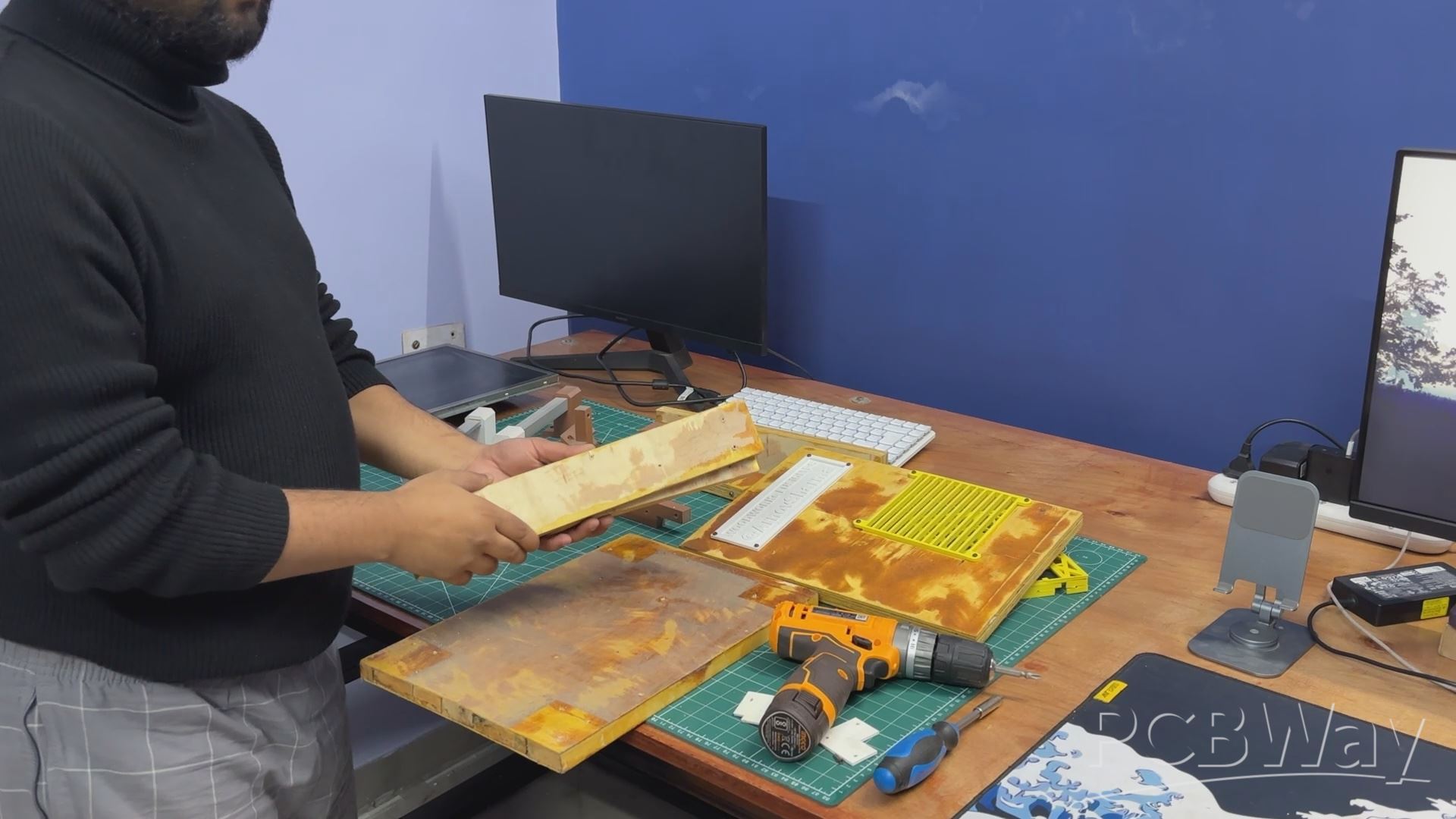
We began the teardown process by harvesting parts from the original WoodWorks Fusion PC. Most of the 3D-printed components—such as the grills, nametag, and motherboard mounts—were disassembled, along with the wooden panels that were joined together using L brackets.
The wooden panels were carefully salvaged, as they would be reused for the new frame assembly, with some modifications planned to adapt them to the updated design.
We even kept some L brackets that were used to mount wooden pieces together.
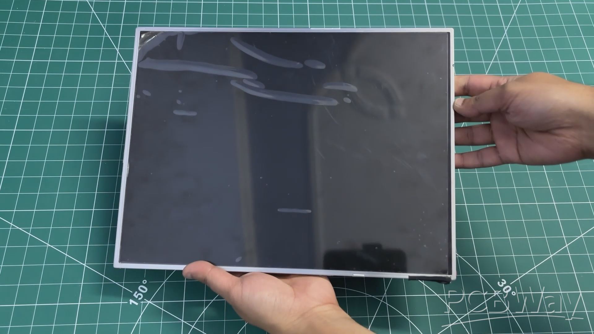
DISPLAY
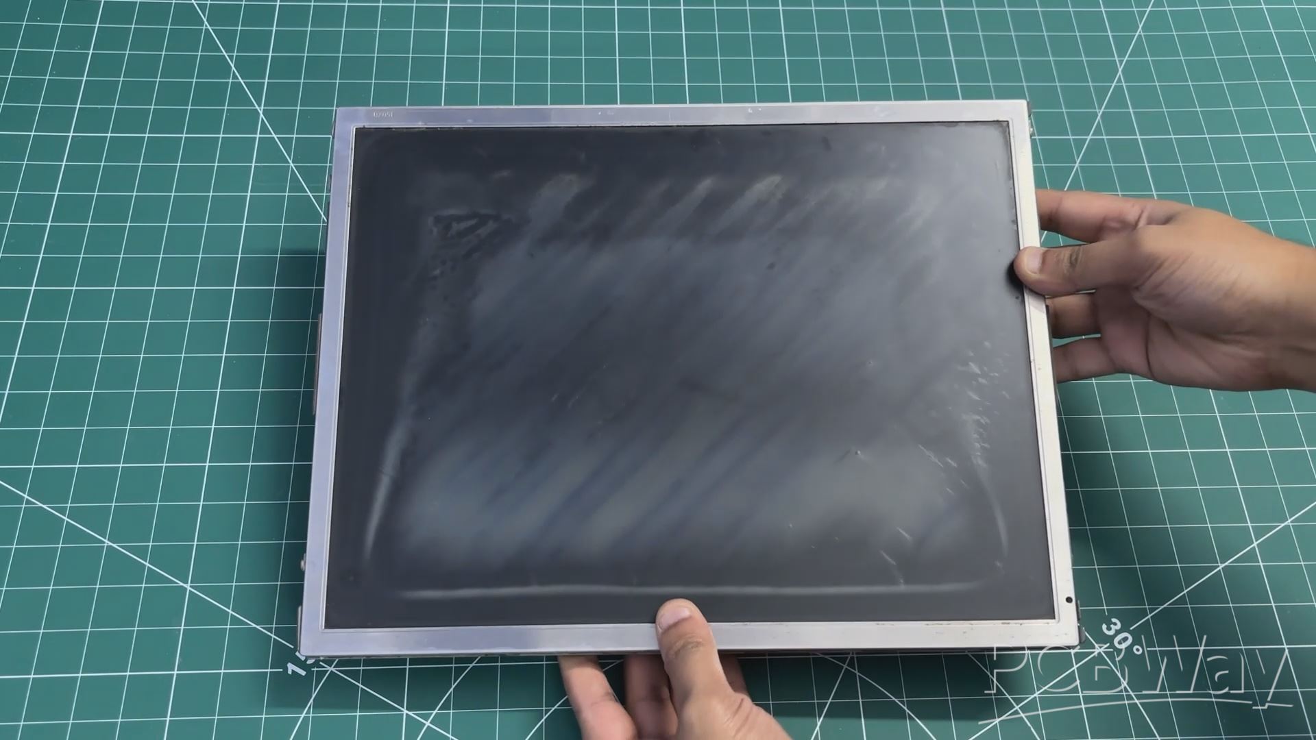
In the previous version of this project, we reused an old LCD monitor from around 2012. It was a Samsung 4:3 display, a format that was very common during the early days of LCD screens.
At the time, most content and applications were designed around this aspect ratio. As display technology evolved, wider screens became the standard, driven by changes in content consumption, improved productivity workflows, and the demand for more immersive experiences in multimedia, professional work, and gaming.
For this revised build, we switched to a much slimmer 15-inch LED display, salvaged from a low-cost monitor purchased for under $25.
We stripped down a low-cost monitor and reused its TFT panel for this project. The monitor’s HDMI driver board was retained, but its original power supply was intentionally omitted. Instead, the display is powered by the same SMPS used for the other internal components. This approach helped reduce the overall size of the wooden frame, making the final build more compact.
LATTEPANDA MU FULL EVALUATION BOARD SETUP
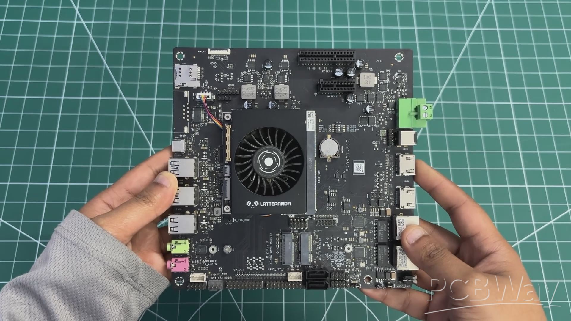
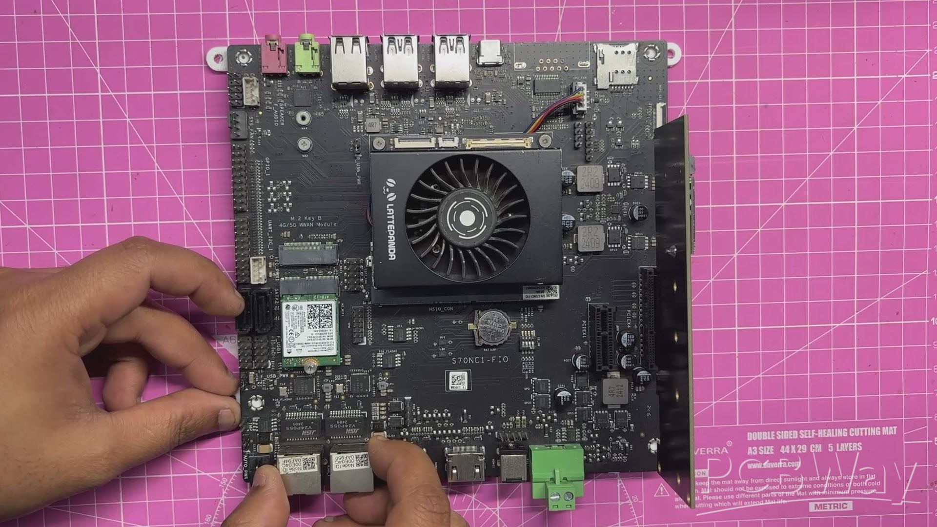
For the main computer in The Parallel Desk, we are using the LattePanda MU, powered by the Intel Core i3-N305 processor.
The LattePanda MU is a compact, SO-DIMM–style compute module that integrates a full x86 PC onto a small form factor. At its core is the Intel Core i3-N305, an 8-core processor based on Intel’s Gracemont architecture, designed for high efficiency while still delivering solid desktop-class performance. This makes it well suited for light gaming, emulation, media playback, and general desktop workloads.
The module comes with 16 GB of LPDDR5 memory onboard, providing high bandwidth and low power consumption, along with onboard NVMe storage, eliminating the need for external SATA or USB boot devices. Graphics are handled by Intel UHD Graphics, which supports modern display standards and hardware-accelerated media decoding. Despite its small size, the MU is essentially a complete PC, requiring only power, I/O, and display connections to function.
One of the most interesting aspects of the LattePanda MU is its modular design. Instead of building around a traditional motherboard, the compute module simply plugs into a carrier or evaluation board—much like laptop RAM—making system integration clean and flexible.
To make the MU usable as a full desktop system, we paired it with the LattePanda MU Full Evaluation Board, which acts as a carrier and breakout platform for all of the module’s interfaces.
The evaluation board exposes standard PC I/O, including multiple USB ports, full-size HDMI and DisplayPort outputs, Gigabit Ethernet, and audio I/O, allowing the MU to be used like a conventional desktop computer. It also provides PCIe expansion, enabling support for high-speed peripherals such as NVMe SSDs, network cards, or other PCIe devices.
The LattePanda MU was chosen because it brings true x86 performance into a very small footprint. Paired with the full evaluation board, it behaves like a traditional desktop PC while remaining compact enough to coexist with a Raspberry Pi Compute Module inside the same enclosure.
Check out one of my previous LattePanda MU-based projects.
https://www.hackster.io/Arnov_Sharma_makes/the-pvm-panda-69cdfa
RASPBERRY PI CM5 SETUP
The second single-board computer used in this project is the Raspberry Pi Compute Module 5. It is powered by the Broadcom BCM2712 quad-core 64-bit Arm Cortex-A76 processor running at 2.4 GHz, offering a significant performance improvement over previous Compute Module generations. The module is available with LPDDR4-4267 SDRAM in 2 GB, 4 GB, 8 GB, and 16 GB variants, all supporting error correction. Storage options include a Lite version with no onboard storage, as well as eMMC capacities of 16 GB, 32 GB, and 64 GB.
For connectivity, the Compute Module 5 supports dual-band Wi-Fi (2.4 GHz and 5 GHz) with IEEE 802.11 b/g/n/ac, Bluetooth 5.0 with BLE, and a Gigabit Ethernet PHY with IEEE 1588 support. Expansion and interfacing options include PCIe Gen 2 with a single x1 root complex at 5 Gbps, USB 3.0 and USB 2.0, and up to 30 configurable GPIO pins operating at 1.8 V or 3.3 V. Additional interfaces such as UART, I2C, SPI, SDIO, DPI (RGB display), I2S, PWM, and GPCLK make the module highly flexible for embedded applications.
In terms of multimedia capabilities, the Compute Module 5 provides two HDMI 2.0 outputs capable of 4K 60 fps, along with two four-lane MIPI connectors for camera and display connectivity. Graphics support includes a 4K 60 fps HEVC decoder, OpenGL ES 3.1, and Vulkan 1.2. Power is supplied through a single 5 V input with USB Power Delivery support, allowing a current draw of up to 5 A. With an operating temperature range of −20°C to +85°C, the module is well-suited for long-term and industrial deployments.
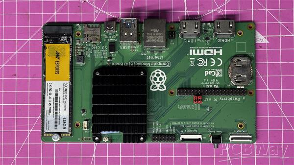
Unlike standard Raspberry Pi boards, the Compute Module 5 does not include onboard USB, HDMI, or Ethernet connectors. Instead, these interfaces are exposed through high-density edge connectors, allowing the module to be used with an evaluation board or a custom carrier board.
The official Compute Module 5 IO Board acts as a breakout platform, exposing all major interfaces of the module. It features a standard 40-pin GPIO header, two full-size HDMI 2.0 ports, two USB 3.0 ports, Gigabit Ethernet with PoE support, and an M.2 PCIe slot for expansion. It also includes two four-lane MIPI DSI/CSI-2 connectors for direct display and camera connections. The board is powered via USB-C, ensuring stable power delivery for high-performance use cases.
One of the main reasons for choosing the Compute Module 5 for this project is its NVMe support and dual full-size HDMI outputs, which make it ideal for Raspberry Pi–based development inside a custom PC enclosure. Since most of my projects are built around Raspberry Pi platforms, having a Compute Module inside this system was an essential design choice for future projects.
Check out a previous CM5-based project of mine.
https://www.hackster.io/Arnov_Sharma_makes/mac-pi-a48047
HDMI SPLITTER
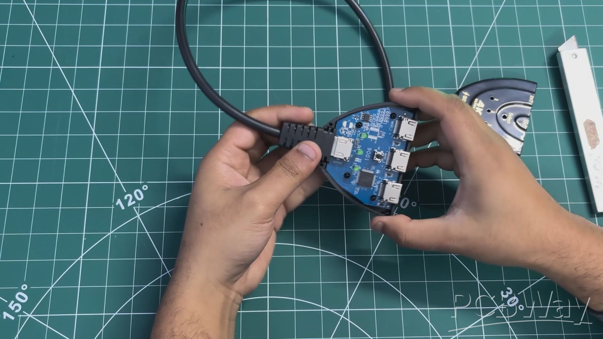
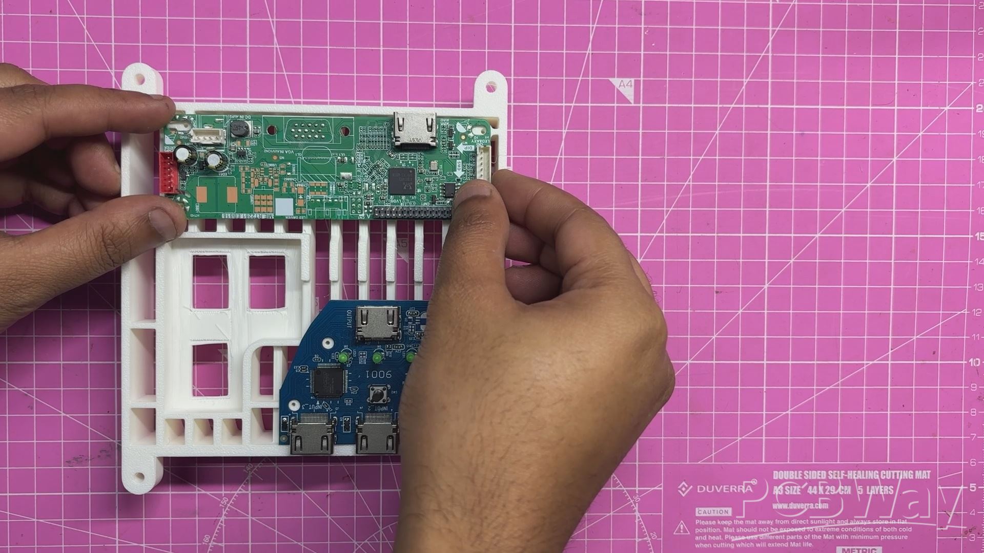
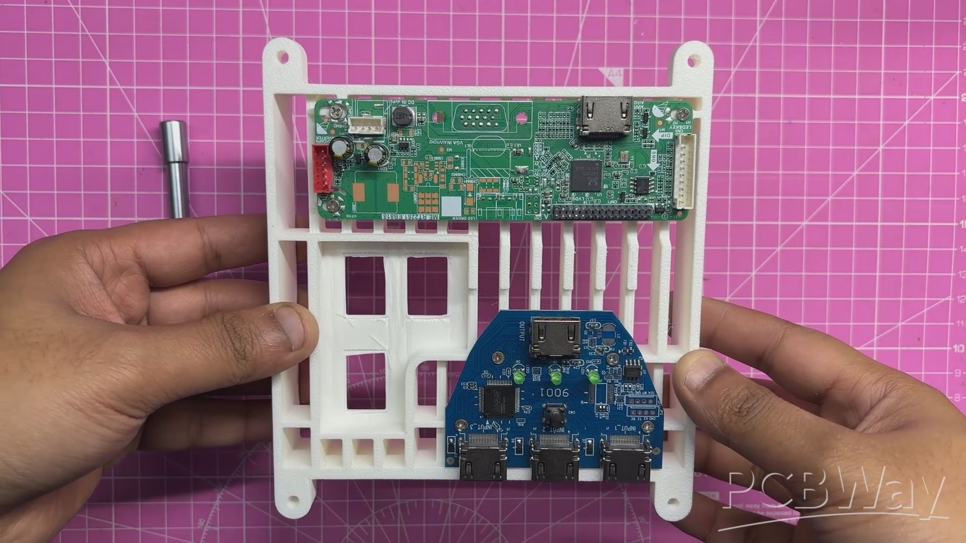
Our goal was to use a single LED display panel as the main display while running two SMPS units. Since only one SBC can drive the display at a time, an HDMI splitter became the obvious solution. We used a three-input, one-output HDMI splitter from Sounce. Opening it up was straightforward—the enclosure doesn’t use screws and is instead held together with snap locks. Using a prying tool, we were able to open the casing and access the circuit inside.
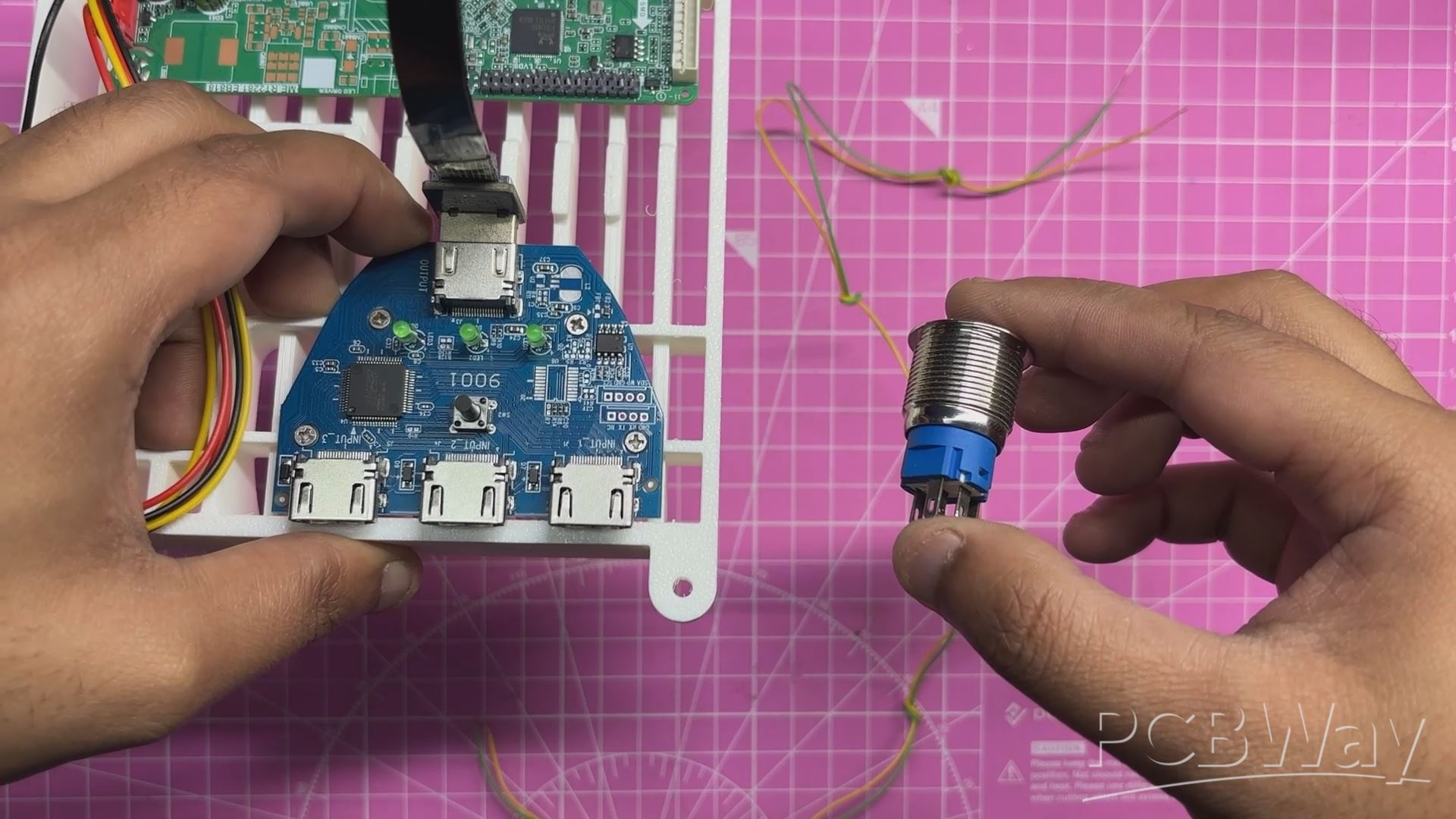
The board features proper HDMI connectors: one output port and three input ports. Each HDMI input has an associated LED indicator that lights up to show which input is currently selected. The main control element on the board is a push button, which allows us to switch the active input connected to the output.
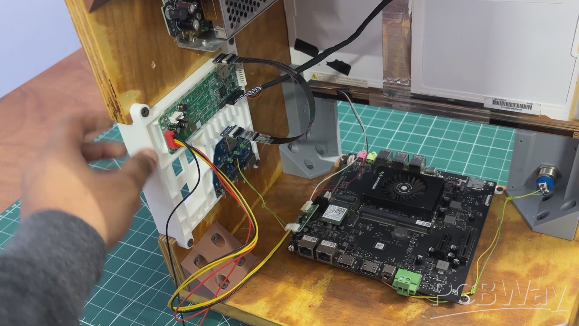
DUAL SBC SAME DISPLAY SETUP
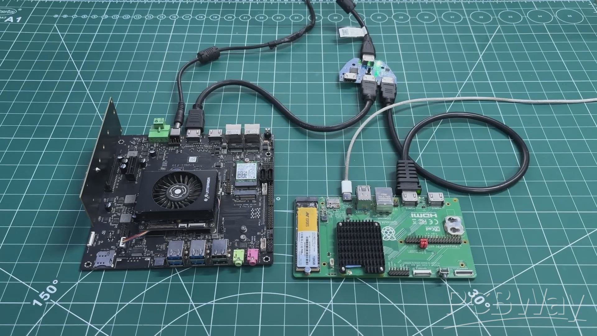
To test the HDMI splitter, we set up a minimal configuration using two SBCs. The HDMI output of the LattePanda was connected to the first HDMI input of the splitter, while the Raspberry Pi Compute Module was connected to the second HDMI input.
A monitor was connected to the HDMI output of the splitter. By default, the display shows the output from the first HDMI input. When the push button is pressed, the display output switches from the first SBC to the second.
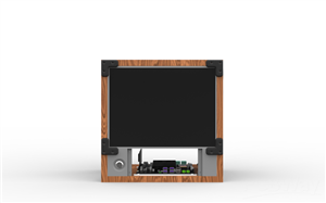
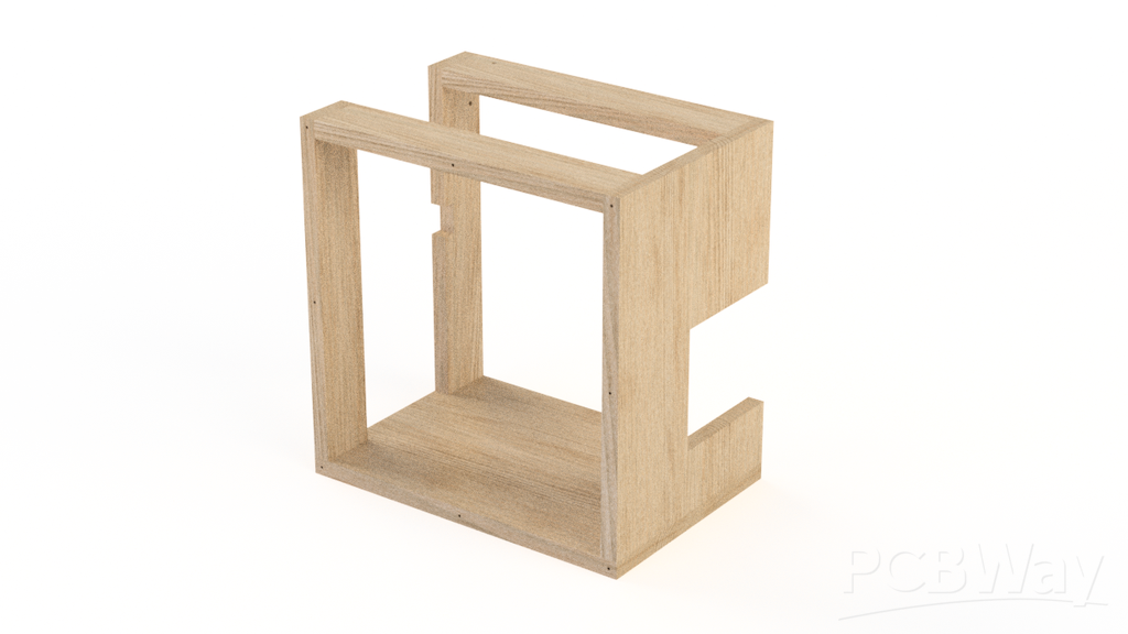
UPDATED 3D DESIGN
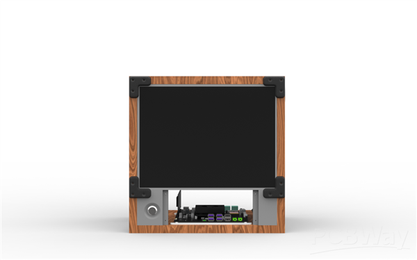
The 3D model for this project was created by reusing and modifying the model from our previous WoodWorks Fusion PC build. Reusing parts from the older project was one of the main goals, as we wanted to evolve the original design rather than start from scratch.
In the updated model, the old display was removed and replaced with a new LED panel. The new screen is slightly smaller and significantly thinner than the previous LCD monitor, which required changes to the overall size of the wooden frame and panels. Along with this, the display holder and the front screen mount were also redesigned.
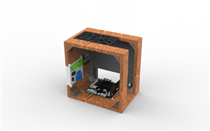
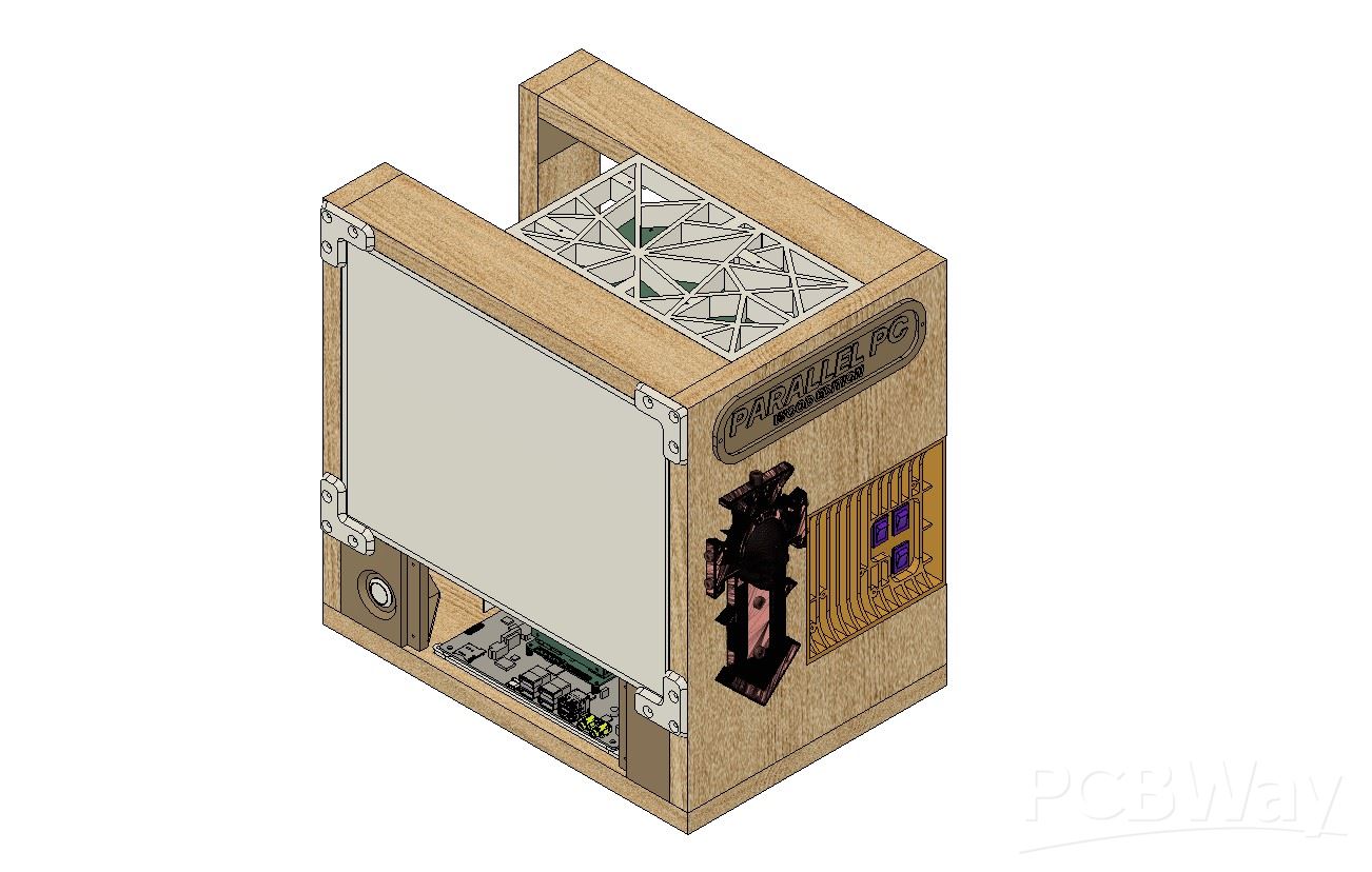
The original motherboard, power supply, and internal hardware were completely removed, leaving the model empty before adding the new components. We then integrated the 3D model of the LattePanda MU expansion board into the frame. The SMPS power supply was also modeled and positioned on the side wooden panel, slightly above the grill area.
The grill section itself was redesigned and now serves as a mounting point for both the HDMI splitter and the display driver board. On the top side, a mesh-style component was modeled, which also functions as the holder for the Raspberry Pi Compute Module.
Finally, a panel-mounted push button was added to the front of the model, which will be used to control the HDMI splitter output.
Below are the 3D model parts we used in this project and their details.
L Bracket with four Holes—a total of six of them are required, and they will be printed using brown PLA with 25% infill. These L brackets were the only things we reused from the previous woodwork fusion PC project.
L Bracket Long Version—This will be used to hold the display in place, and we need two of them with the same print settings and 25% infill.
Lattepanda MU Holder—The MU Holder was printed in White Hyper PLA, with an infill of 50%.
Screen Holder Front—four pieces were printed with Black Hyper PLA with 50% infill each.
Raspberry Pi CM5 board Frame/Grill—This grill-holder part was printed in Hyper Black PLA with an infill of 30%.
SIDE GRILL—This part was printed with White Hyper PLA.
Display Holder—We printed this part (two holders) with grey PLA with an infill of 25%.
Nametag—We printed this part with white Hyper PLA with an infill of 25%.
This is link for 3D MODEL https://a360.co/3MQalQh
WOODEN PANEL SIZE EDIT
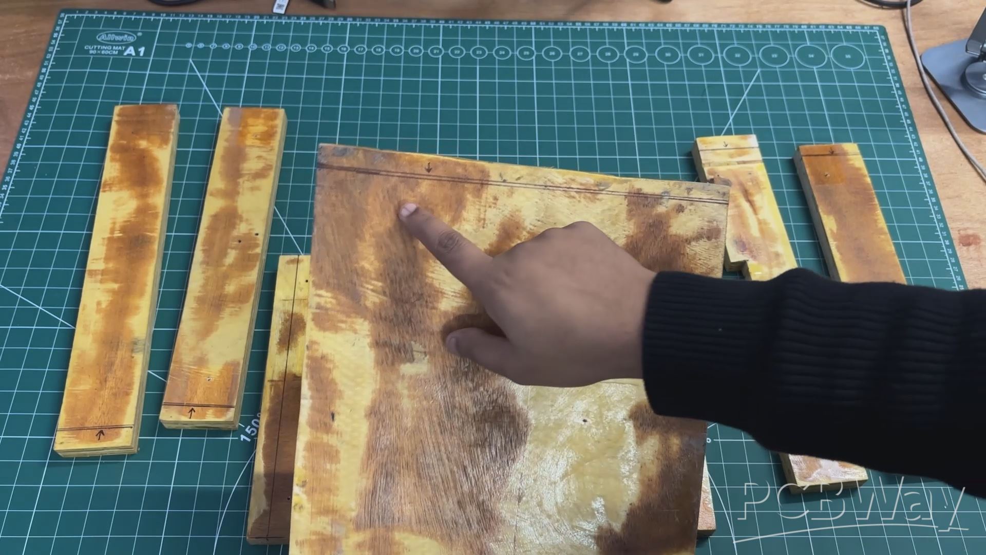
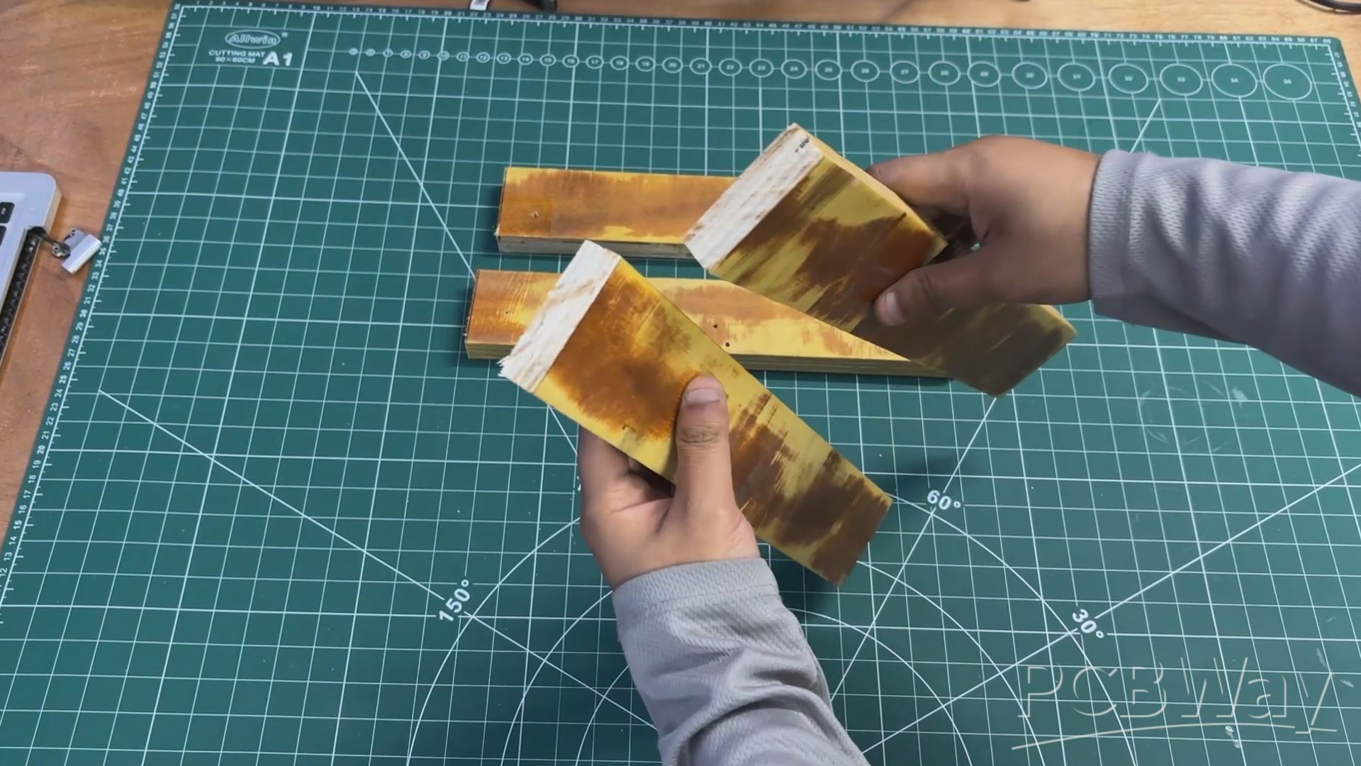
The wooden panels harvested from the original WoodWorks Fusion PC needed to be trimmed to match the updated frame dimensions.
Using the measurements defined in the CAD model, we marked the required length and width on each panel and removed the excess material using a power saw.
This ensured that all panels matched the new frame size accurately and were ready for assembly.
PCB DESIGN- LC FILTER
In our project, we wanted to use a 12 V, 5 A SMPS, which may or may not have voltage ripple at its output. These SMPS units are generally fine for driving MCUs, relay boards, motors, and other crude electronics, but something more sensitive—like an SBC or a display—can get affected by the ripple and noise generated by these supplies.
One option would be to use a well-branded SMPS, such as ones made by Mean Well or Honeywell, but those supplies are expensive. Also, in the local market, it is common to find power supplies that claim to be from these brands but may actually be knockoffs. Because of this, our approach was to improve the output quality of the SMPS by adding an LC filter circuit on the output side.
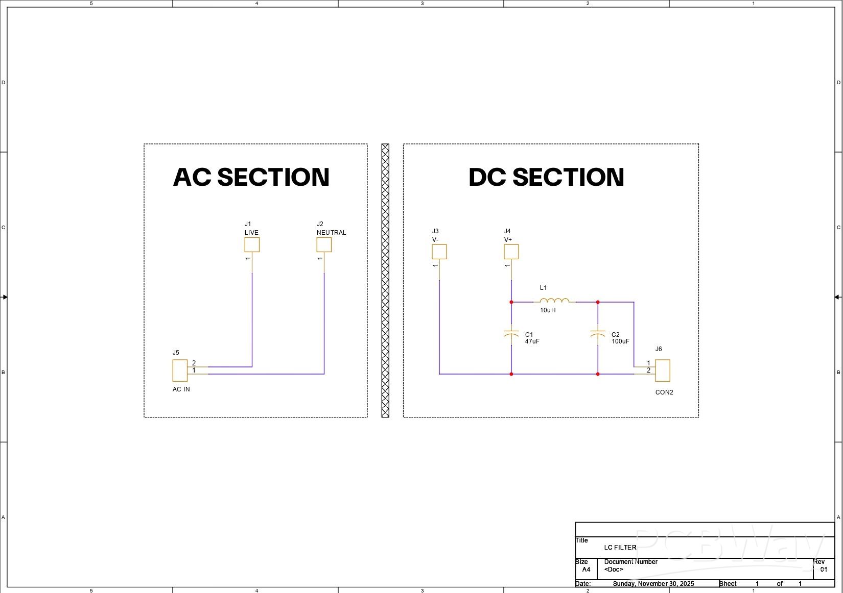
The LC filter is implemented by connecting a 10 µH inductor in series with the positive output line. On both sides of the inductor, decoupling capacitors are connected between the supply rail and ground, forming a C–L–C (π-filter) configuration. The capacitor placed before the inductor helps absorb high-frequency switching noise coming directly from the SMPS, while the capacitor placed after the inductor smooths the remaining ripple and provides a more stable voltage to the load.
At the input side of the filter, we used a 47 µF, 100 V capacitor, and at the output side, we used a 100 µF, 63 V capacitor. This simple LC filter significantly improves the DC output quality of the SMPS, making it suitable for powering sensitive loads like SBCs and displays.
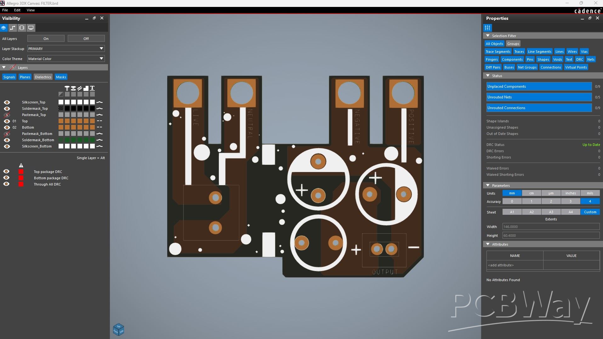
After preparing the schematic, we started the PCB design process. The board outline was taken directly from the CAD model prepared earlier and used as the main PCB outline. The AC terminal was placed close to the AC input side, and the C–L–C filter configuration was placed near the DC output side to keep the power path short and clean.
The mounting holes on the PCB are plated, so when the PCB is mounted onto the SMPS using bolts, the PCB makes a secure electrical and mechanical connection with the SMPS terminals. This ensures a reliable connection between the SMPS and the filter PCB.
PCBWAY SERVICE
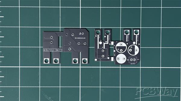
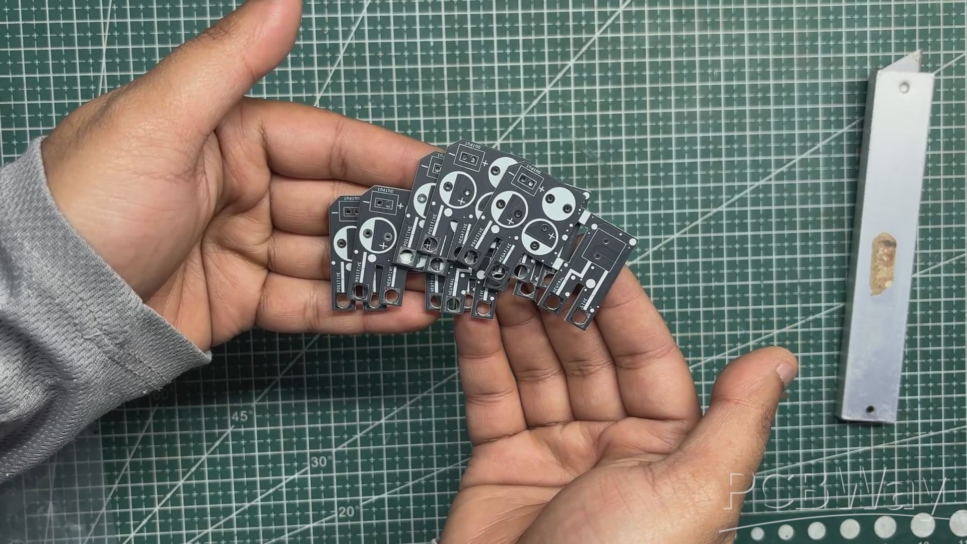
After finalizing the PCB design, we exported the Gerber files and uploaded them to the quote page on PCBWay. For this project, we chose a matte black solder mask with white silkscreen.
The PCBs were delivered within a week, and the quality was excellent, as always. While I usually stick to white or standard black solder masks for most of my builds, this time I decided to try PCBWay’s matte black finish. This was partly inspired by their Christmas sale campaign, during which matte black, purple, and pink solder mask options were available for a limited time. The matte black finish added a subtle, premium look that fit the project perfectly.
Over the past ten years, PCBWay has distinguished themselves by providing outstanding PCB manufacturing and assembly services, becoming a trusted partner for countless engineers and designers worldwide.
Also, PCBWay is organizing the PCBWay 8th Project Design Contest, a global event that invites makers, engineers, and innovators to showcase their most creative builds. With categories in Electronics, Mechanical, and AIoT, it’s a great opportunity to share your work, connect with the community, and compete for exciting prizes.
You guys can check out PCBWAY if you want great PCB service at an affordable rate.
PCB ASSEMBLY
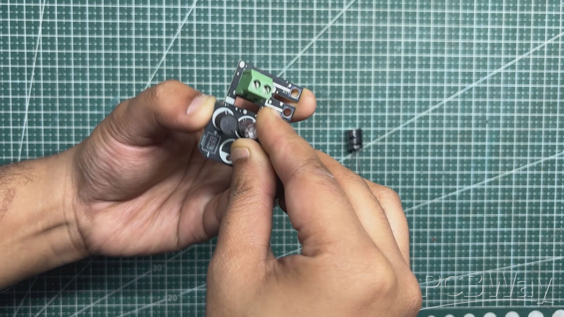
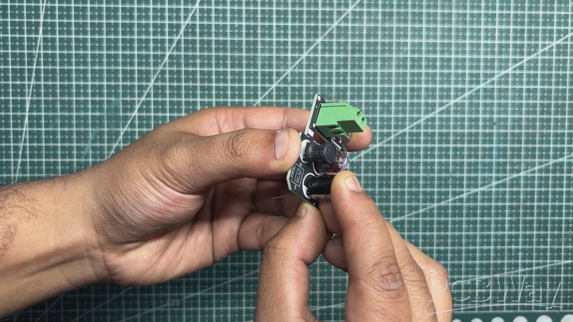
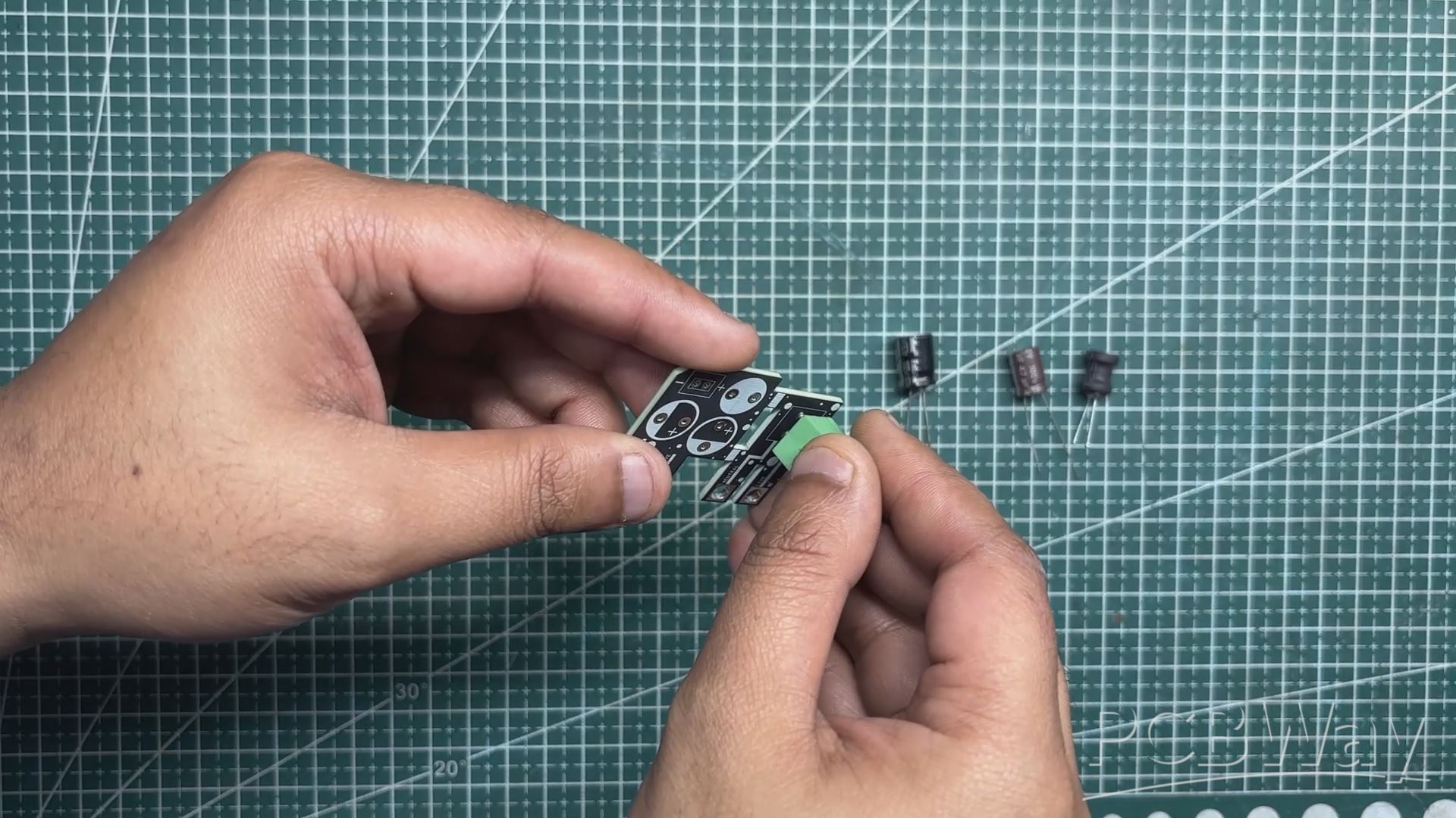
The filter circuit was assembled using only through-hole components. Assembly began with the placement of the CON2 screw terminal, followed by the 10 µH inductor.
Next, the input-side capacitor was installed, followed by the output capacitor.
Once all components were placed, the board was flipped over and the leads were soldered using a soldering iron.
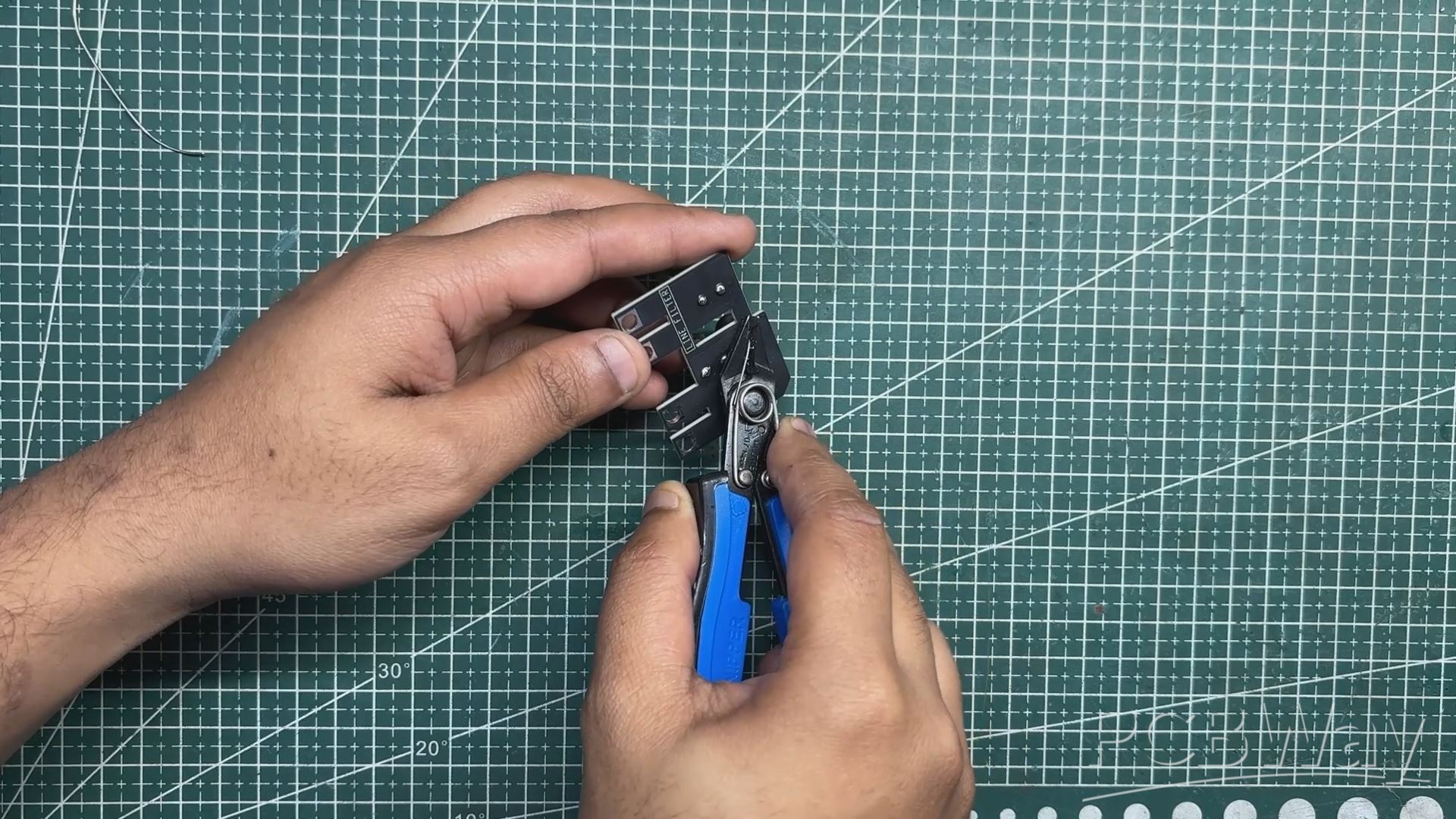
After soldering, the excess lead length was trimmed using a nipper plier to complete the assembly.
FILTER CIRCUIT & SMPS ASSEMBLY

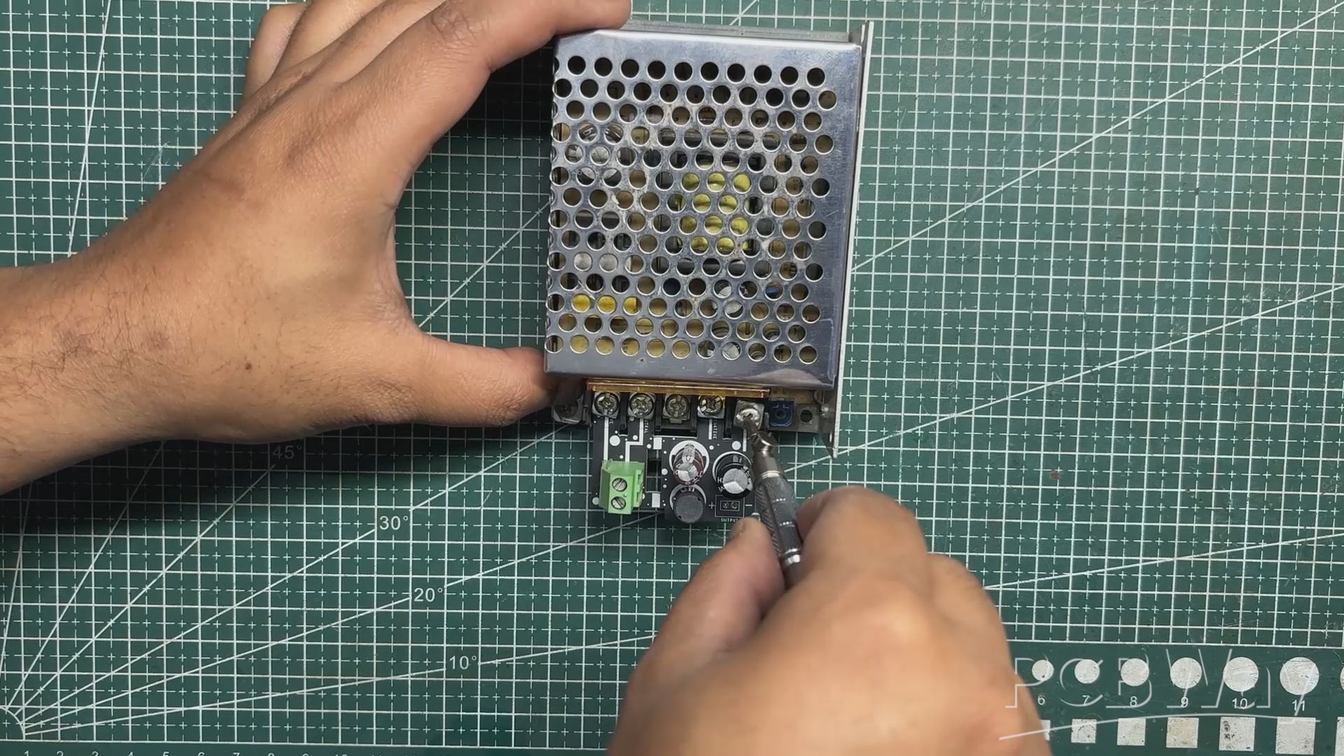
The assembled filter circuit was positioned over the mounting holes of the SMPS, ensuring that the PCB was properly aligned.
Four mounting screws were then used to secure the board firmly in place, allowing the PCB traces to interface cleanly with the SMPS connections.
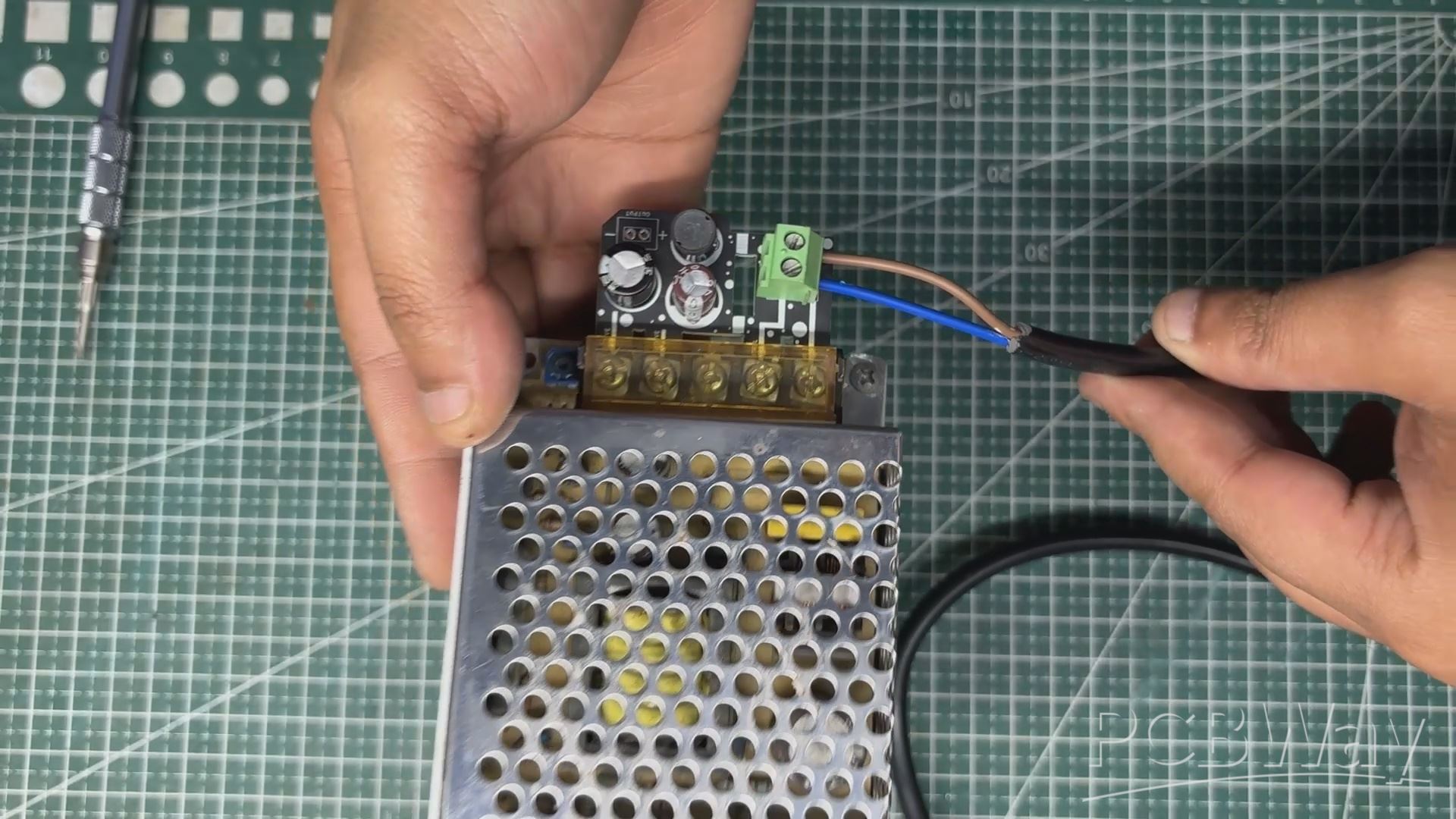
Next, a power cord was connected to the SMPS by wiring the live and neutral lines of the mains cable to the CON2 screw terminal on the filter circuit.
FILTER CIRCUIT TEST
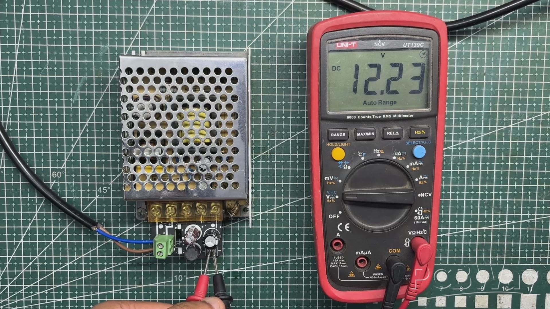

We first plugged the AC cord into the mains socket and measured the input voltage, which was around 260 V AC. Next, we measured the voltage at the output of the filter circuit and obtained a stable 12.2 V DC. This stable output is achieved by adding our LC filter at the SMPS output, which helps suppress switching noise and smooth out voltage ripple.
To verify the effectiveness of the filter, we measured the output using an oscilloscope. The scope showed a ripple of approximately 40 mV peak-to-peak, indicating that the high-frequency noise from the SMPS has been significantly attenuated. This level of ripple is well within acceptable limits and is well-suited for our SBC and display loads.
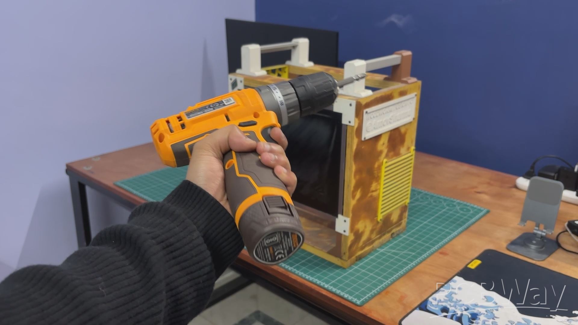
PARALLEL PC WOODEN ENCLOSURE ASSEMBLY
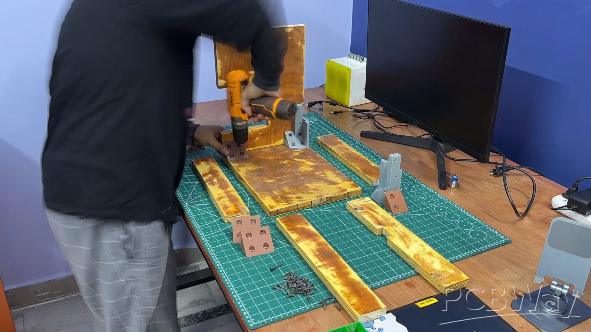
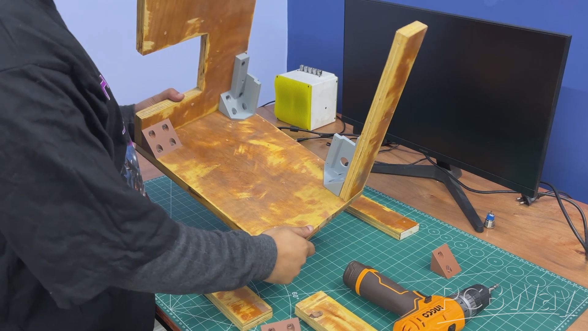
As mentioned earlier in the build log, we followed the assembly sequence defined in the 3D model. We started by attaching the right-side panel to the base using L-brackets and one of the display holder brackets. These were secured using M4 wood screws, and an electric screwdriver–drill combo was used to speed up the process.
Next, the left-side panel was added and fixed in place using two additional L-brackets.
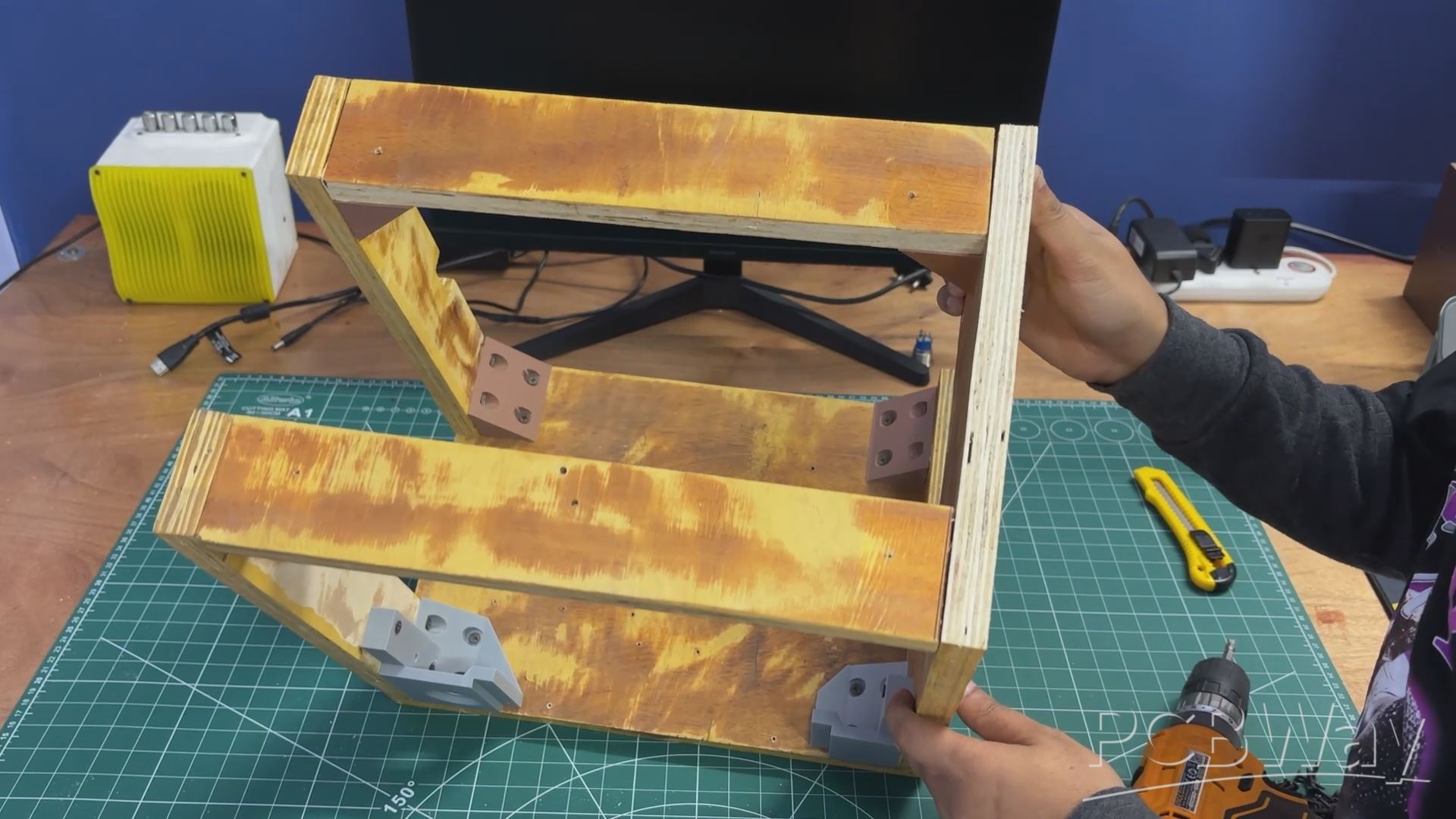
After that, four L-brackets were mounted on the top side panels—two per panel.
The top panel was then positioned and secured to both the left and right side panels.
The result of this process is a rigid wooden frame assembly that serves as the main enclosure for the PC.
SIDE GRILL ASSEMBLY
We began the side grill assembly by positioning both the HDMI splitter board and the display driver board onto their respective mounting bosses.
The HDMI splitter was secured using four M2 screws, while the display driver was mounted using three M2 screws.
To connect the HDMI output of the splitter to the HDMI input of the display driver, we used a right-angle HDMI breakout board. This breakout uses an FPC cable, making it ideal for tight spaces and close-proximity HDMI connections inside the enclosure.
Next, we installed the CON6 JST connector that came with the display. This connector is used to supply 12 V power to the display panel.
Finally, two wires were connected to the terminals of the HDMI splitter’s push button. These wires were soldered to a panel-mounted push button installed on the front face of the PC. This effectively extends the splitter’s button, allowing the user to switch the display output directly from the front panel.
LATTEPANDA MU HOLDER
The MU holder assembly process was straightforward.
The LattePanda MU full evaluation board was placed onto the 3D-printed holder, ensuring that all mounting holes were properly aligned.
Four M2 screws were then used to secure the evaluation board to the holder.
Before mounting, the PCIe-to-M.2 adapter card was temporarily removed, as it obstructed one of the mounting holes.
Once the evaluation board and 3D-printed holder were securely fastened, the PCIe-to-M.2 adapter was reinstalled into the PCIe slot.
LATTEPANDA MU WITH FRAME ASSSEMBLY
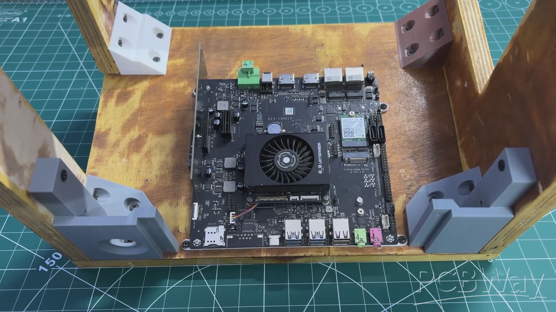
We placed the LattePanda MU holder in its position as defined in the CAD model. Next, we used four M3 screws to secure it to the wooden base, making sure that the USB port side was oriented toward the front of the enclosure.
RASPBERRY PI COMPUTE MODULE HOLDER ASSEMBLY
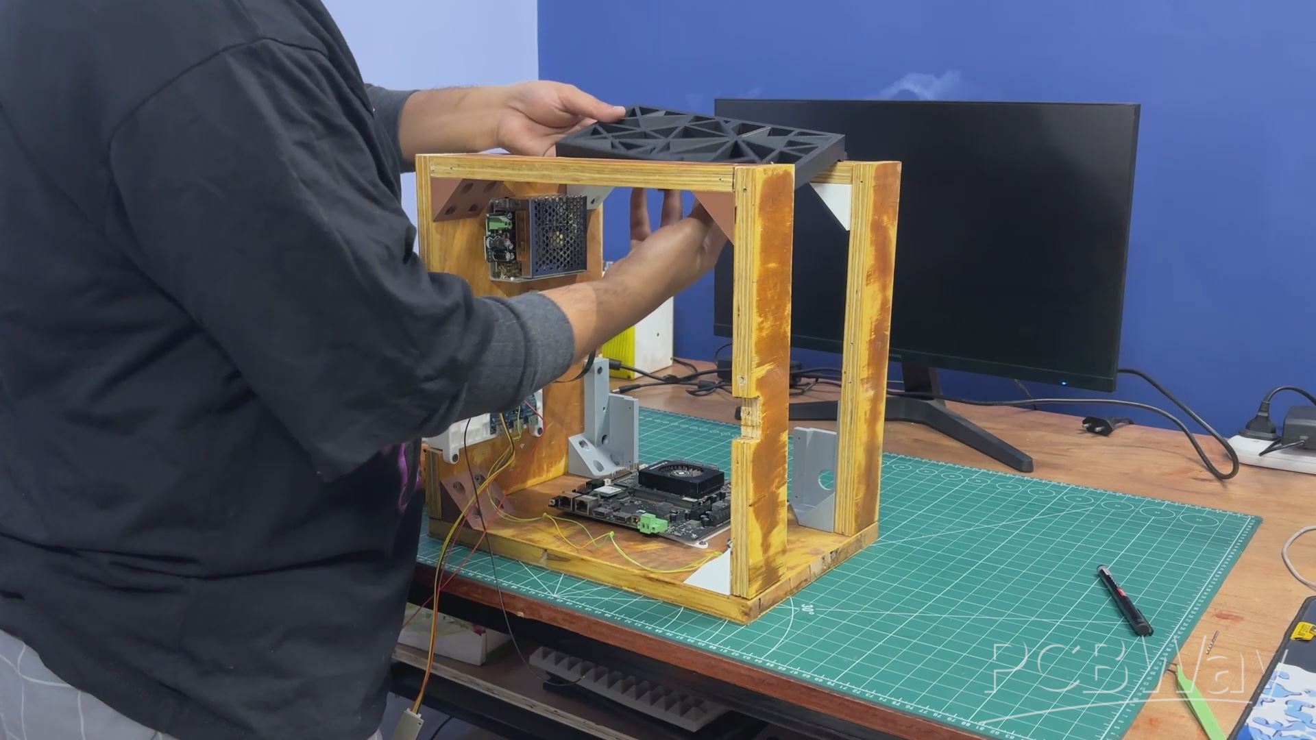
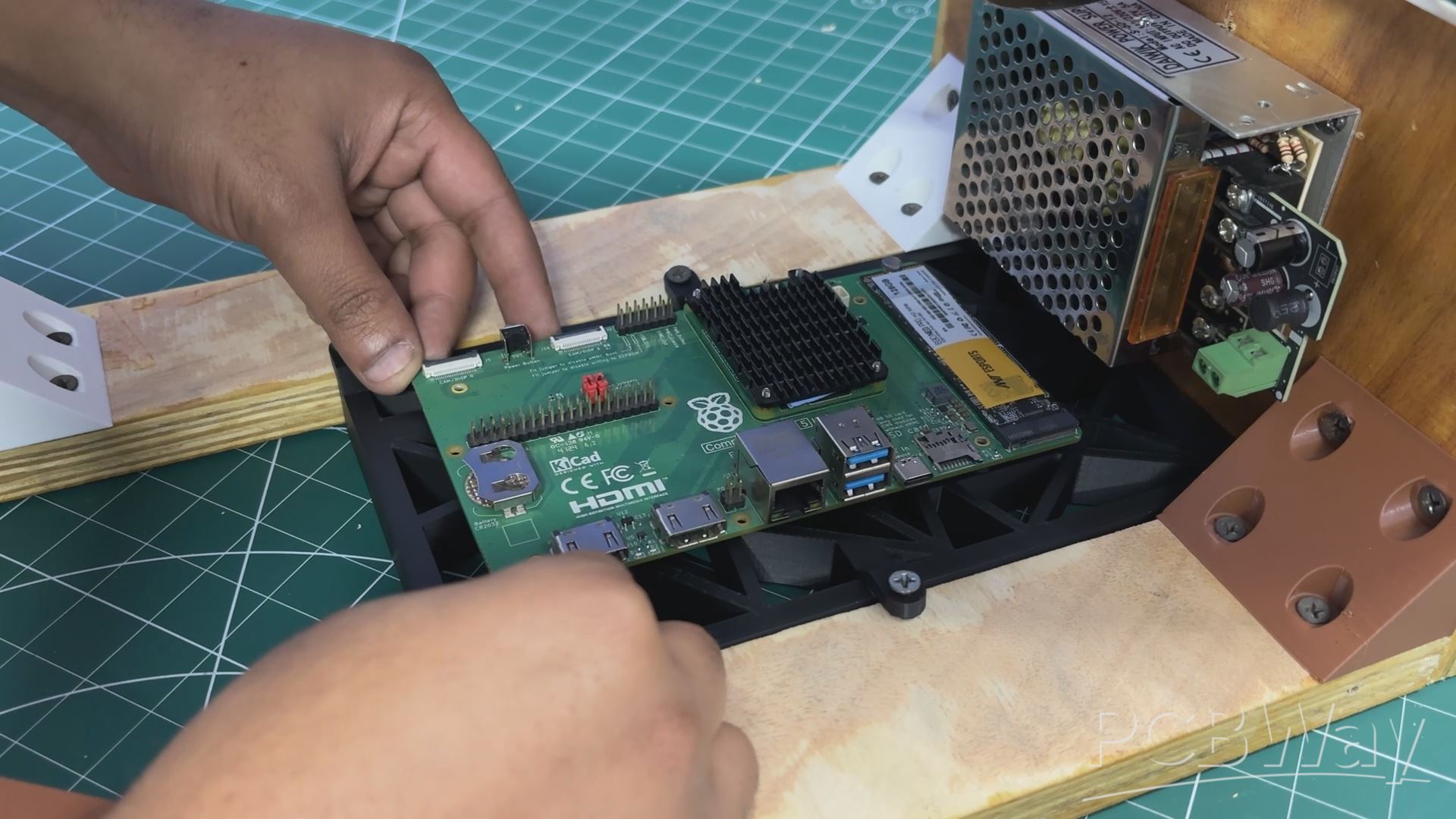
We then assembled the Raspberry Pi Compute Module. First, the Pi holder was placed at the top between the two wooden panels as defined in the CAD model and secured using four M4 wood screws.
Next, the entire PC was flipped upside down, and the Compute Module expansion board was positioned over the Pi holder’s mounting bosses. Both were then secured together using four M2.5 screws, completing the Raspberry Pi Compute Module holder assembly.
FRONT SWITCH ASSEMBLY

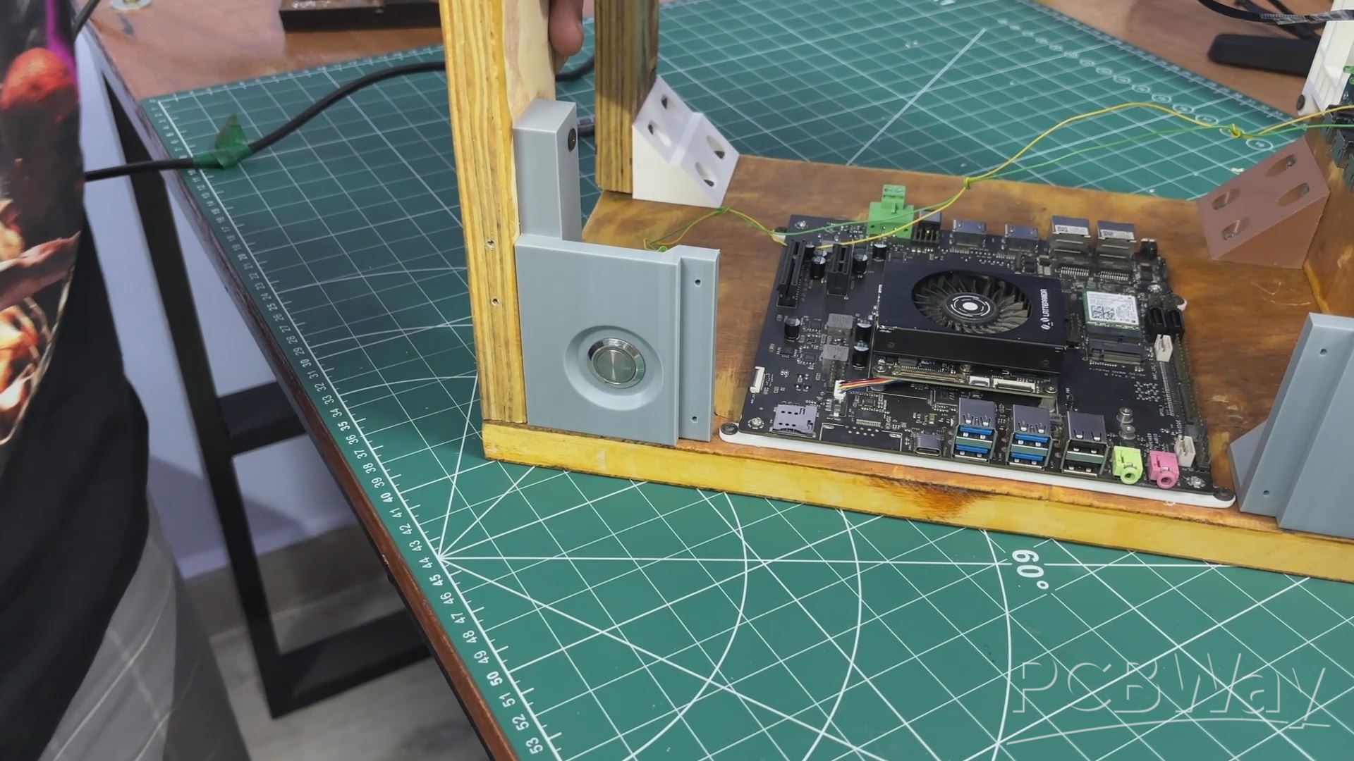
We began the front switch assembly by desoldering the existing switch wires. The switch was then passed through the hole provided in the front display holder. Since it is a panel-mount push button with a nut-and-bolt-style design, it was secured in place by tightening the nut.
After mounting the switch, the wires were resoldered to the switch terminals, completing the assembly. The HDMI output can now be controlled directly using the front-mounted button.
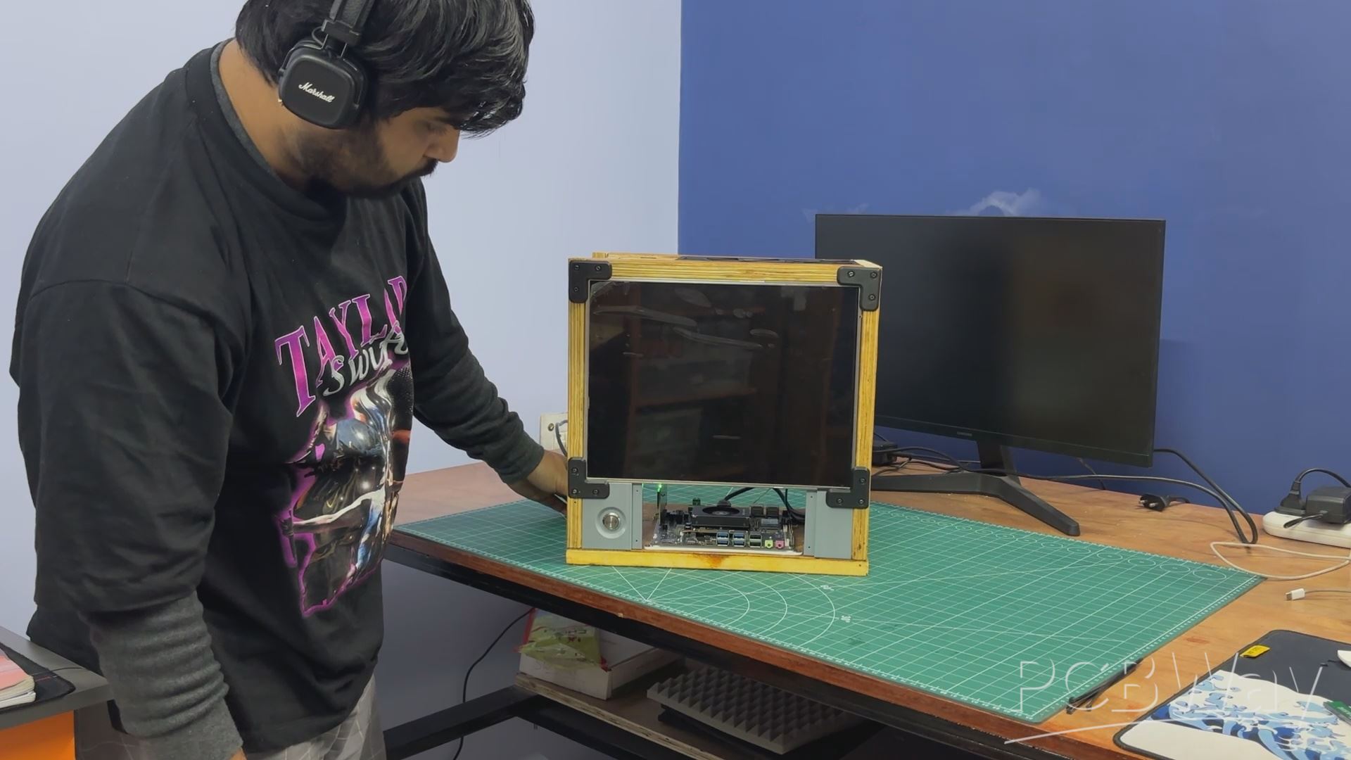
LED DISPLAY FRAME ASSEMBLY
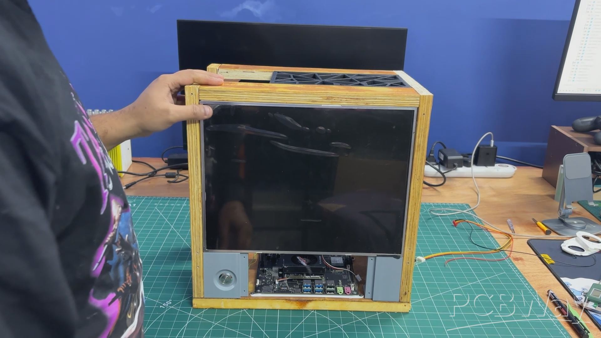
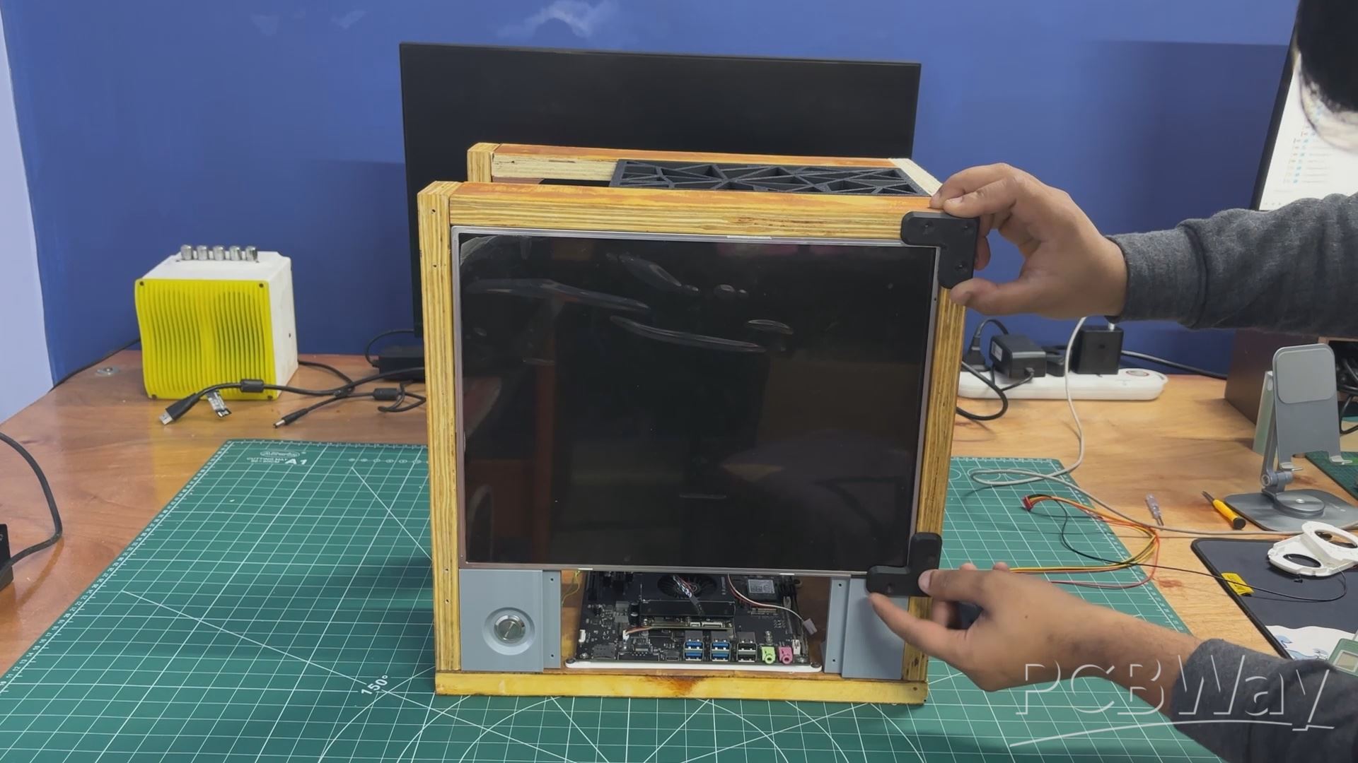
The display was installed from the front side and positioned in place. It was then secured using four screen holders, with one holder attached at each corner to lock the screen firmly.
From the inside, the screen backlight driver board was connected using the provided connector, which was plugged into the display driver. The positive and negative leads from this connector were then soldered to the corresponding positive and negative terminals of the SMPS.
This supplies a stable 12 V output from the SMPS to power the display.
POWER SOURCE WIRING
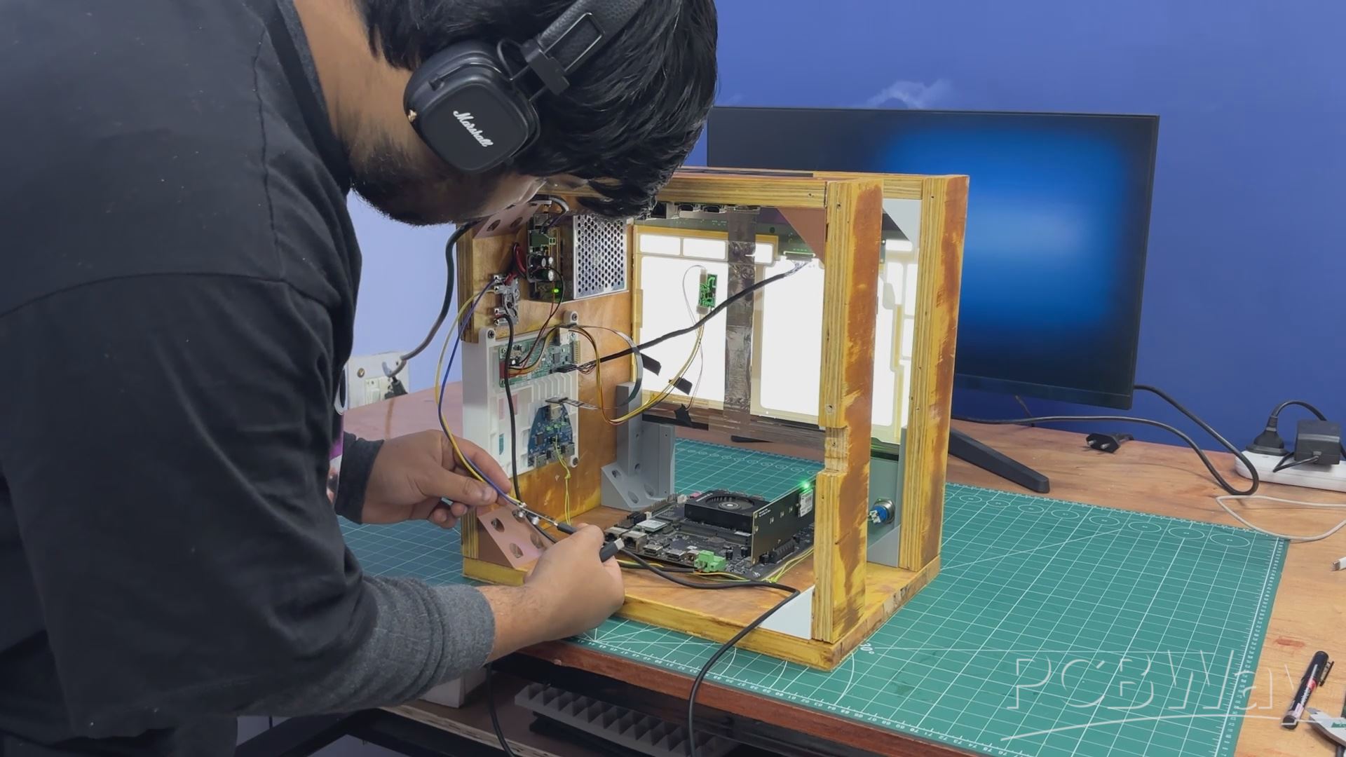
For getting power from the LC filter circuit, we used a simple makeshift solution. A bare filter circuit PCB was mounted on the side panel near the SMPS using wood screws. The 12 V and GND outputs from the LC filter were routed to this bare PCB, effectively turning it into a small power distribution board. This allowed us to easily solder additional loads and kept the wiring process simple and organized.
Next, we added a 12 V-to-5 V, 5 A buck converter board with a USB-PD output. The input of the buck converter was connected to the VCC and GND rails of the filter circuit through the distribution board. This buck converter is used to power the Raspberry Pi Compute Module setup.
We then connected another set of wires from the 12 V and GND outputs of the LC filter to the screw terminals on the LattePanda MU expansion board. Once the SMPS was powered on, both the LattePanda MU and the display turned on, confirming that the setup was functioning correctly.
In the final step, a USB-C–to–USB-C PD cable was connected from the buck converter’s USB-C port to the Raspberry Pi Compute Module expansion board. Powering the system again confirmed that the Pi booted successfully, validating the entire power distribution setup.
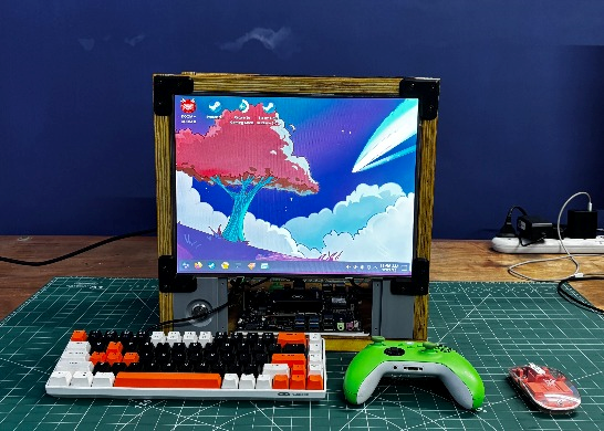
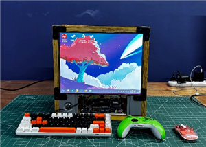
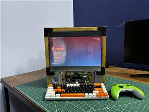
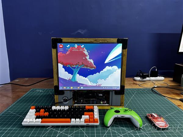
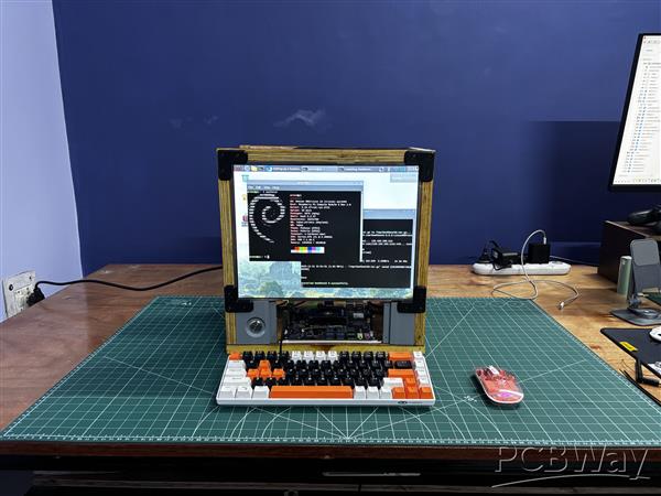
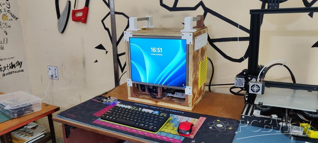
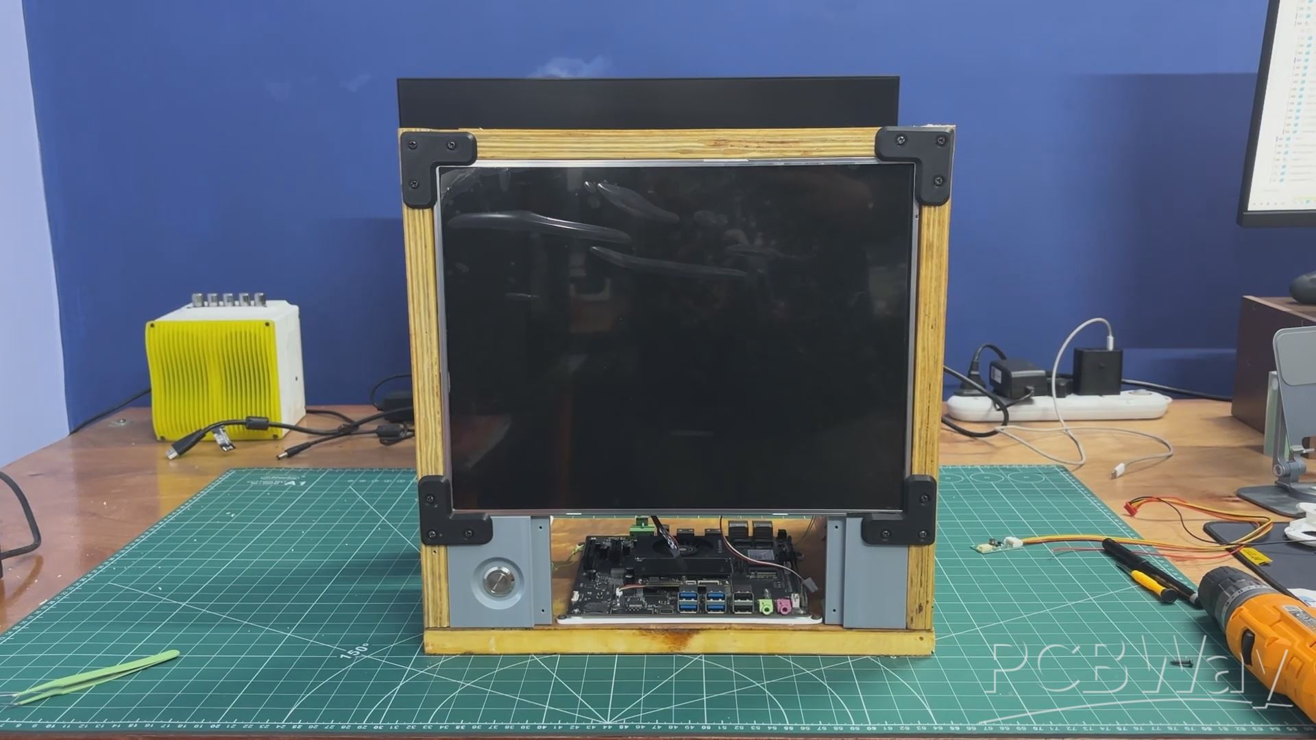
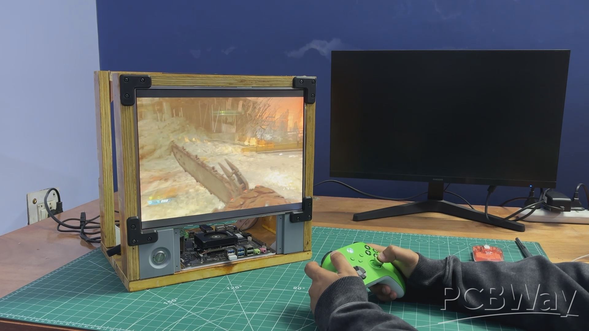
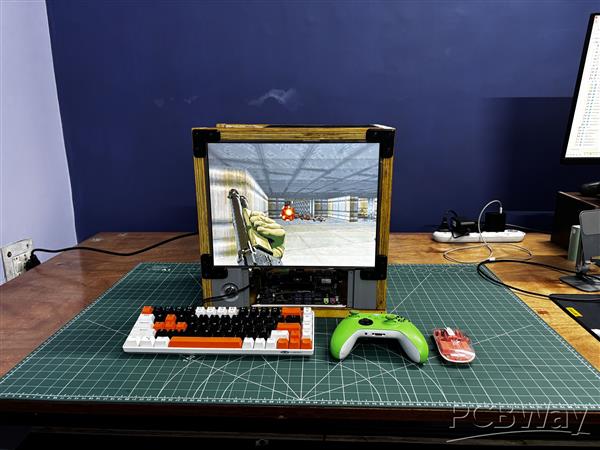
RESULT
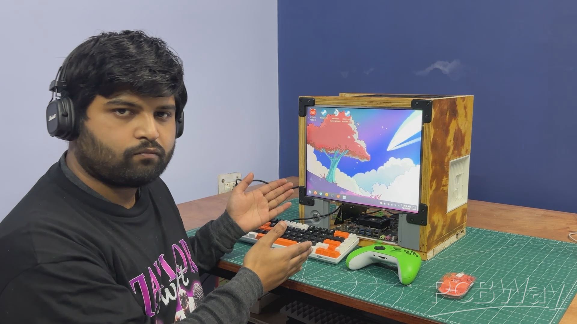
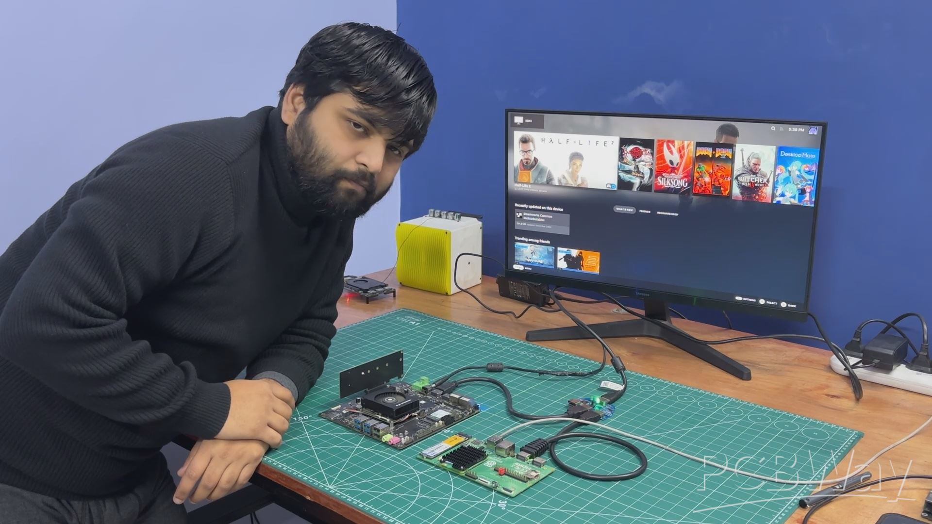
Here’s the final result of this simple yet time-intensive build: Parallel PC—Wood Edition. It’s a balanced blend of wood and 3D-printed components, brought together to create a custom all-in-one PC that features not one, but two different computing platforms. One system is an ARM-based SBC, while the other is an x86 machine powered by a mobile processor.
Having two computers in a single enclosure allows us to switch between platforms depending on the task. We can work on Raspberry Pi–based projects and embedded development, then seamlessly switch over to x86 for workloads that require it. In our case, the LattePanda MU runs Bazzite, giving us access to Steam and enabling proper PC gaming—all within the same machine.
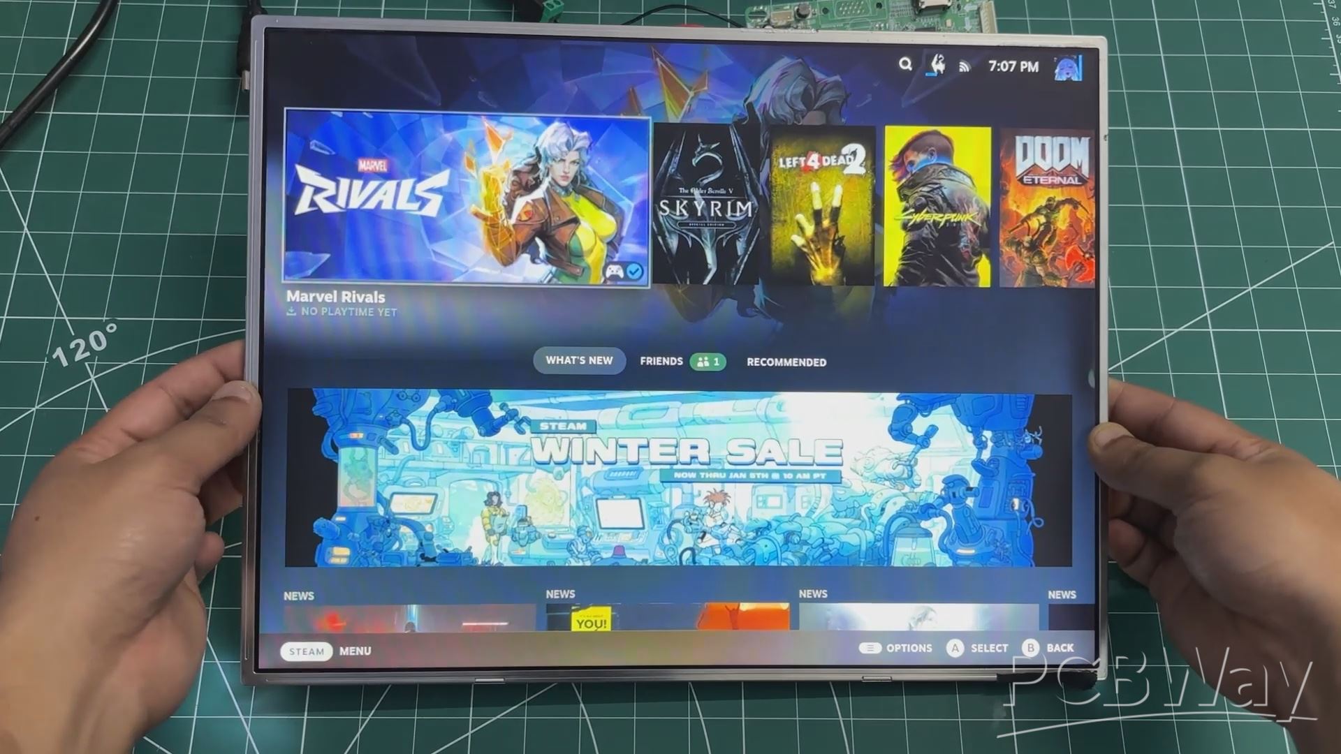
STEAM ON BAZZITE
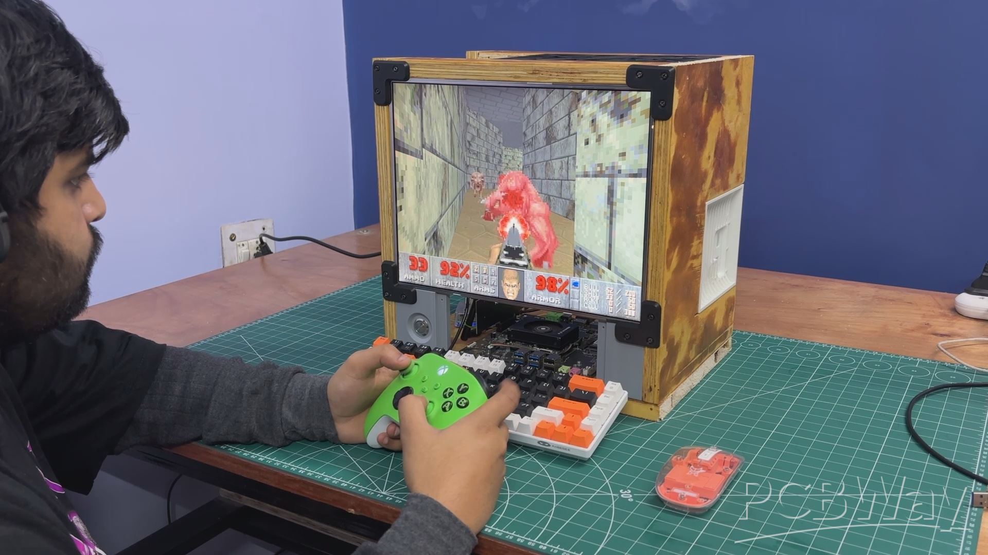

The very first thing we did on the Parallel PC was open Steam on the LattePanda MU.
And, as tradition demands, the sacred question was asked: can it run Doom?
The answer was yes. Doom (1993) ran buttery smooth—which honestly wasn’t shocking. At this point Doom has been run on everything from calculators to receipt printers, so the N305 barely breaks a sweat.
Naturally, we got cocky and asked the next question: can it run Doom Eternal? Surprisingly yes again. The game hovered around a playable 30 FPS and felt totally usable. And remember—this is without a dedicated GPU, which makes it even more impressive.
Riding that high, we went full send and tried Cyberpunk 2077. That’s where reality stepped in. At around 5–10 FPS, the experience was more slideshow than game—but hey, it did launch and run, and that alone feels like a small victory.
Next up was NieR: Automata, which ran incredibly smoothly and ended up being the best-performing title we tested. We followed that with Left 4 Dead 2 and The Elder Scrolls V: Skyrim, both of which ran without any issues. These tests confirmed that the setup shines when it comes to older and moderately demanding games.
In a future revision, we plan to add a dedicated GPU and run these tests again to see just how far we can push this system.
Another big win with running Bazzite on the LattePanda MU is that it’s not just about gaming. You can drop straight into desktop mode and get a full Linux environment with a proper terminal—perfect for tinkering, testing, and doing regular Linux stuff in between game sessions.
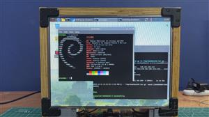
RASPBERRY PI OS (TRIXIE)
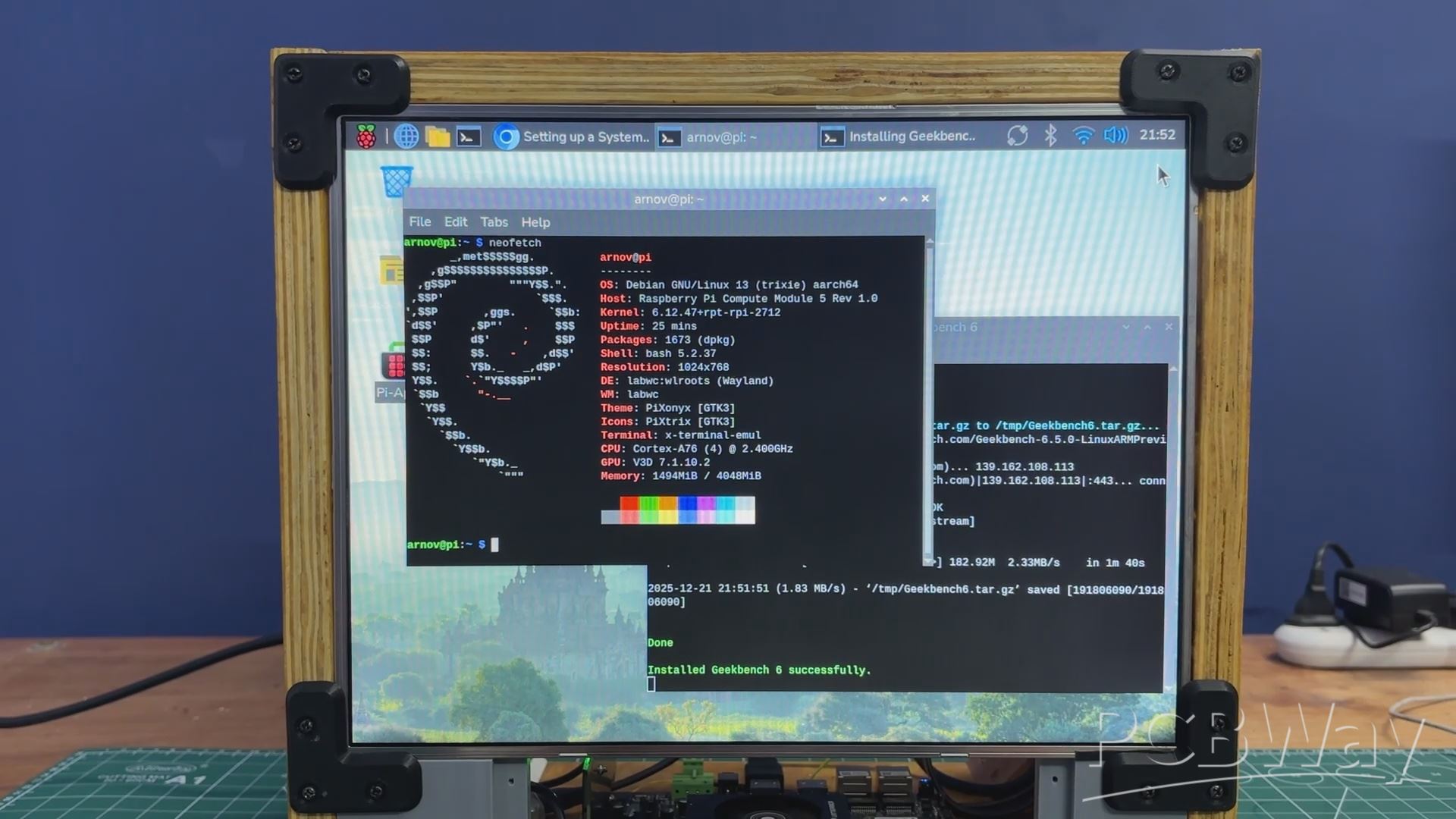
Next, using the front-mounted button, we switch the display output from the LattePanda MU to the Raspberry Pi Compute Module 5, which is running the new Trixie OS—a port of Debian Trixie.
Once switched, the system behaves like a full Raspberry Pi 5–class setup. It supports everything people typically use a Pi for, including general Linux desktop work, coding and scripting, hardware interfacing, and embedded project testing. It can even run Steam—we’ve already shared a YouTube Short where we tested Half-Life and Minecraft Java on a Pi 5.
The system can be used for writing and compiling code, running Python scripts, experimenting with GPIO, and working with networking tools and services. Tasks such as controlling LEDs and sensors, running a local web server, or building and testing IoT applications are all possible using the integrated CM5 inside the Parallel PC.
One planned upgrade for Version 2 is to add a breakout board that brings the GPIO pins from inside the enclosure to the front panel, allowing quick connections to the CM5 using jumper wires.
CONCLUSION & WHAT'S NEXT?
Overall, this setup works remarkably well in its current form. The dual-system approach allows seamless switching between an ARM-based Raspberry Pi environment and an x86 desktop system, making the machine flexible and genuinely useful in day-to-day workflows. The shared display, compact layout, and modular construction validate the core idea behind Parallel PC—Wood Edition.
That said, there are a few areas planned for improvement in future revisions. Audio output is currently missing, and the LattePanda MU would benefit from a dedicated GPU for improved graphics performance. On the Raspberry Pi side, a front-mounted expansion board and GPIO breakout would make prototyping more accessible. Additional covers on the left side of the enclosure are also planned to clean up the overall look.
There’s also plenty of room to experiment further. Adding internal partitions within the frame would allow more compute modules to be integrated, potentially turning this into a multi-computer platform. Future ideas include adding sensors, experimenting with a RISC-V–based system, expanding storage, and making aesthetic upgrades such as painting or finishing the wooden panels.
Overall, the project has been a success and serves as a strong foundation for future iterations. A new revision is already in the works, which will incorporate many of these improvements and push the concept even further.
In addition, we appreciate PCBWAY's support of this project. Visit them for a variety of PCB-related services, such as stencil and PCB assembly services, as well as 3D printing services.
Thanks for reaching this far, and I will be back with a new project pretty soon.
Peace.
PARALLEL PC- Wood Edition
*PCBWay community is a sharing platform. We are not responsible for any design issues and parameter issues (board thickness, surface finish, etc.) you choose.


Raspberry Pi 5 7 Inch Touch Screen IPS 1024x600 HD LCD HDMI-compatible Display for RPI 4B 3B+ OPI 5 AIDA64 PC Secondary Screen(Without Speaker)
BUY NOW


- Comments(1)
- Likes(4)
More by Arnov Arnov sharma
-
 DIY XBOX Controller
Greetings everyone, and welcome back. Here's something fun and custom.This is my version of an Xbox ...
DIY XBOX Controller
Greetings everyone, and welcome back. Here's something fun and custom.This is my version of an Xbox ...
-
 Pocket SNES
Greetings everyone, and welcome back! Today, I’ve got something fun and tiny to share—the Pocket SNE...
Pocket SNES
Greetings everyone, and welcome back! Today, I’ve got something fun and tiny to share—the Pocket SNE...
-
 Batocera Arcade Box
Greetings everyone and welcome back, Here's something. Fun and nostalgic. Right now, we are using ou...
Batocera Arcade Box
Greetings everyone and welcome back, Here's something. Fun and nostalgic. Right now, we are using ou...
-
 64x32 Matrix Panel Setup with PICO 2
Greetings everyone and welcome back.So here's something fun and useful: a Raspberry Pi Pico 2-powere...
64x32 Matrix Panel Setup with PICO 2
Greetings everyone and welcome back.So here's something fun and useful: a Raspberry Pi Pico 2-powere...
-
 Portable Air Quality Meter
Hello everyone, and welcome back! Today, I have something incredibly useful for you—a Portable Air Q...
Portable Air Quality Meter
Hello everyone, and welcome back! Today, I have something incredibly useful for you—a Portable Air Q...
-
 WALKPi PCB Version
Greetings everyone and welcome back, This is the WalkPi, a homebrew audio player that plays music fr...
WALKPi PCB Version
Greetings everyone and welcome back, This is the WalkPi, a homebrew audio player that plays music fr...
-
 Delete Button XL
Greetings everyone and welcome back, and here's something fun and useful.In essence, the Delete Butt...
Delete Button XL
Greetings everyone and welcome back, and here's something fun and useful.In essence, the Delete Butt...
-
 Arduino Retro Game Controller
Greetings everyone and welcome back. Here's something fun.The Arduino Retro Game Controller was buil...
Arduino Retro Game Controller
Greetings everyone and welcome back. Here's something fun.The Arduino Retro Game Controller was buil...
-
 Super Power Buck Converter
Greetings everyone and welcome back!Here's something powerful, The SUPER POWER BUCK CONVERTER BOARD ...
Super Power Buck Converter
Greetings everyone and welcome back!Here's something powerful, The SUPER POWER BUCK CONVERTER BOARD ...
-
 Pocket Temp Meter
Greetings and welcome back.So here's something portable and useful: the Pocket TEMP Meter project.As...
Pocket Temp Meter
Greetings and welcome back.So here's something portable and useful: the Pocket TEMP Meter project.As...
-
 Pico Powered DC Fan Driver
Hello everyone and welcome back.So here's something cool: a 5V to 12V DC motor driver based around a...
Pico Powered DC Fan Driver
Hello everyone and welcome back.So here's something cool: a 5V to 12V DC motor driver based around a...
-
 Mini Solar Light Project with a Twist
Greetings.This is the Cube Light, a Small and compact cube-shaped emergency solar light that boasts ...
Mini Solar Light Project with a Twist
Greetings.This is the Cube Light, a Small and compact cube-shaped emergency solar light that boasts ...
-
 PALPi V5 Handheld Retro Game Console
Hey, Guys what's up?So this is PALPi which is a Raspberry Pi Zero W Based Handheld Retro Game Consol...
PALPi V5 Handheld Retro Game Console
Hey, Guys what's up?So this is PALPi which is a Raspberry Pi Zero W Based Handheld Retro Game Consol...
-
 DIY Thermometer with TTGO T Display and DS18B20
Greetings.So this is the DIY Thermometer made entirely from scratch using a TTGO T display board and...
DIY Thermometer with TTGO T Display and DS18B20
Greetings.So this is the DIY Thermometer made entirely from scratch using a TTGO T display board and...
-
 Motion Trigger Circuit with and without Microcontroller
GreetingsHere's a tutorial on how to use an HC-SR505 PIR Module with and without a microcontroller t...
Motion Trigger Circuit with and without Microcontroller
GreetingsHere's a tutorial on how to use an HC-SR505 PIR Module with and without a microcontroller t...
-
 Motor Driver Board Atmega328PU and HC01
Hey, what's up folks here's something super cool and useful if you're making a basic Robot Setup, A ...
Motor Driver Board Atmega328PU and HC01
Hey, what's up folks here's something super cool and useful if you're making a basic Robot Setup, A ...
-
 Power Block
Hey Everyone what's up!So this is Power block, a DIY UPS that can be used to power a bunch of 5V Ope...
Power Block
Hey Everyone what's up!So this is Power block, a DIY UPS that can be used to power a bunch of 5V Ope...
-
 Goku PCB Badge V2
Hey everyone what's up!So here's something SUPER cool, A PCB Board themed after Goku from Dragon Bal...
Goku PCB Badge V2
Hey everyone what's up!So here's something SUPER cool, A PCB Board themed after Goku from Dragon Bal...
-
Programmable Mist Maker - XIAO / QT PY Extension
800 1 0 -
RadioHAT - Raspberry Pi radio development platform
644 0 1 -
-
-
-
-
ARPS-2 – Arduino-Compatible Robot Project Shield for Arduino UNO
3112 0 6 -
A Compact Charging Breakout Board For Waveshare ESP32-C3
3731 3 8 -
AI-driven LoRa & LLM-enabled Kiosk & Food Delivery System
4055 2 2


