


|
KiCad 9.0 |
|

|
STM32CubeIDESTMicroelectronics
|
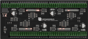
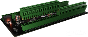
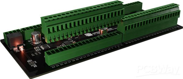
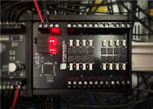
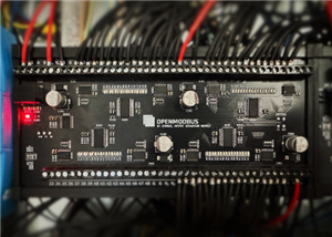
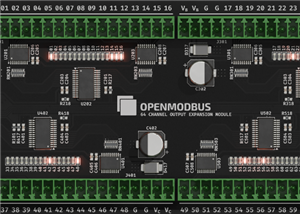
Open Modbus OM-64DO - 64-channel Modbus RTU output module
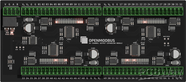
A compact industrial-grade 64-channel Modbus RTU output module featuring low-side drivers, per-channel LEDs, wide input voltage, DIN-rail support, and full configuration via Modbus holding registers. Designed for automation, distributed I/O, and custom control applications.
1. Product Overview
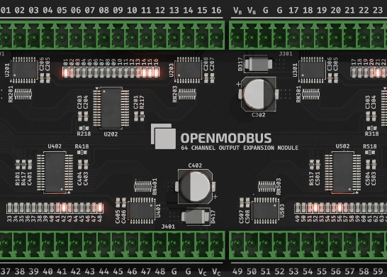
The Open Modbus OM-64DO is a 64-channel low-side output expansion module intended for industrial automation, machine control, and distributed I/O networks using Modbus RTU over RS-485.
It switches DC loads such as solenoids, relays, indicator lamps, locks, and alarms up to 48 VDC.
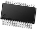
The module combines an STM32G031 microcontroller, four MCP23S17 SPI expanders, and eight TBD62083 Darlington driver arrays.
This architecture enables reliable, flexible, and scalable output control with built-in protection and per-channel LED indication.
📦 Hardware Files
The full schematic, PCB layout, and BOM are available at:
- Schematic → https://github.com/OpenModbus/OM-64DO/blob/main/assets/schematics.pdf
- PCB Design → https://github.com/OpenModbus/OM-64DO/blob/main/assets/board_design.pdf
- BOM → https://github.com/OpenModbus/OM-64DO/blob/main/production/OM-64DO.csv
2. Key Features
- 64 open-collector low-side outputs
- Up to 500 mA per output, 2 A max per driver package
- 5–48 VDC recommended load voltage (50 V absolute maximum)
- Wide supply input: 7–28 VDC
- RS-485 Modbus RTU communication (THVD1450 transceiver)
- Fully configurable serial parameters
- Per-channel LED indicators
- DEGSON 15EDG pluggable screw terminals
- DIN-rail mount using UM72S profile
- Compact PCB (163.1 × 72 mm)
3. Applications
Ideal for:
- PLC expansion
- Building automation
- Access control
- Alarm and signaling systems
- Relay switching
- Industrial prototyping
4. Hardware Architecture
Microcontroller
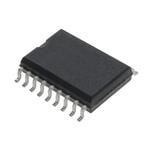
The STM32G031F8P6 MCU handles Modbus RTU processing, configuration storage, SPI communication, and output refresh logic.
I/O Expanders
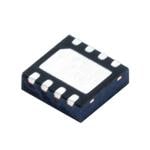
Four MCP23S17 SPI-based expanders provide the 64 output control signals in groups of 16.
Output Drivers
The TBD62083 Darlington arrays switch the actual loads.
Their key characteristics include:
- 8 channels per IC
- 500 mA per channel
- 2 A total per IC
- Integrated flyback diodes
- LED indication per channel
RS-485 Communication
A robust THVD1450 transceiver provides differential RS-485 communication with:
- Fail-safe features
- High ESD immunity
- Suitable for long cable runs
Power
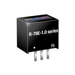
The board accepts 7–28 VDC and includes a high-efficiency R-78E3.3-1.0 regulator for its 3.3 V logic domain.
5. Electrical Specifications
Supply
- 7–28 VDC input
- Internal regulated 3.3 V logic
- Low power MCU operation
Outputs
- 64 open-collector low-side channels
- 5–48 VDC recommended load
- 50 VDC absolute maximum
- 500 mA max per output
- 2 A max per driver IC
- Built-in flyback protection
- LED indicator on each output
Communication
- RS-485, 2-wire
- Modbus RTU protocol
- Default settings: 9600 baud, 8N1, address 1
- All communication parameters can be reconfigured via holding registers
6. Mechanical Information
- PCB: 163.1 × 72 mm
- DIN-rail enclosure compatibility: UM72S profile
- DEGSON 15EDG pluggable screw terminals
- Mounting suitable for industrial control cabinets
7. Functional Overview
Each output activates when its Modbus coil value is 1, causing the driver to sink current to ground.
When the coil value is 0, the channel turns off, leaving the load unpowered.
A dedicated LED mirrors the state of each output channel.
8. Modbus Interface
Supported Function Codes
- 0x01 — Read Coils
- 0x05 — Write Single Coil
- 0x0F — Write Multiple Coils
- 0x03 — Read Holding Registers
- 0x06 — Write Single Register
- 0x10 — Write Multiple Registers
Coils (Outputs 1–64)
Coils map directly to output channels.
Addressing begins at 0x00.
Mapping available here: https://github.com/OpenModbus/OM-64DO?tab=readme-ov-file#coils-outputs-164
Holding Registers
Configuration registers start at 0x00 and are stored in non-volatile memory.
Mapping available here: https://github.com/OpenModbus/OM-64DO?tab=readme-ov-file#holding-registers
Example Modbus Commands
Below are typical Modbus RTU frames for controlling and configuring the OM-64DO.
Turn ON Output 1
Function: Write Single Coil (0x05)
Coil address: 0x0000
Value: ON → 0xFF00
Frame: 01 05 00 00 FF 00 8C 3A
Turn ON Outputs 5–12
Function: Write Multiple Coils (0x0F)
Start address: 0x0004
Quantity: 0x0008 (8 coils)
Data: FF (all eight bits ON)
Frame: 01 0F 00 04 00 08 01 FF 4F 15
Turn ON All Outputs (1–64)
Function: Write Multiple Coils (0x0F)
Start address: 0x0000
Quantity: 0x0040 (64 coils)
Data: FF FF FF FF FF FF FF FF
Frame: 01 0F 00 00 00 40 08 FF FF FF FF FF FF FF FF AA 20
Turn OFF All Outputs
Function: Write Multiple Coils (0x0F)
Start address: 0x0000
Quantity: 0x0040
Data: 00 00 00 00 00 00 00 00
Frame: 01 0F 00 00 00 40 08 00 00 00 00 00 00 00 00 EB A4
Read All Outputs
Function: Read Coils (0x01)
Start address: 0x0000
Quantity: 0x0040
Frame: 01 01 00 00 00 40 3D FA
Set Device Address
Function: Write Single Register (0x06)
Register: 0x0000 (Slave Address)
Value: 0x0005
Frame: 01 06 00 00 00 05 49 C9
Set Baud Rate
Function: Write Single Register (0x06)
Register: 0x0001 (Baud Rate Code)
Value: 0x0007 → 115200 baud
Frame: 01 06 00 01 00 07 99 C8
9. Wiring
The OM-64DO uses low-side (open-collector) switching.
That means the module connects the load to ground when ON, and the load must be powered from your external power supply.
The 64 outputs are grouped into four banks of 16 (Bank A–D).
This allows one board to drive devices powered from different voltages simultaneously.
Examples:
- Bank A → 12 V devices
- Bank B → 24 V relays
- Bank C → 48 V solenoids
- Bank D → 5 V indicators
Low-Side Output Principle
Each output contains a protected Darlington transistor that sinks current:
Load +V ─────── Load ─────── OUTx (SINK)
Recommended Wiring Steps
- Connect the load voltage (5–48 VDC) to the Vx terminal of the bank.
- Connect the output pin (OUTx) to the negative side of the load.
- Tie power supply GND to OM-64DO GND.
- Ensure the supply can support the total current of that bank.
⚠️ Important Grounding Requirement:
All load power supplies must share a common ground with the OM-64DO.
This is required for the low-side drivers and internal logic to reference the same electrical 0 V.
Wiring Example
The example below shows how to drive 24 V and 12 V relays at the same time using separate banks.
- Bank A (VA) → 24 V relays
- Bank B (VB) → 12 V relays
- Both supplies share a common ground
- Loads return their negative side to the selected OUTx channel

This wiring approach can be extended to all four banks, each with its own voltage.
10. Safety Notes
- Do not exceed 50 VDC load voltage
- Ensure load currents stay within limits
- For inductive loads, external suppression can further improve reliability
- Maintain proper RS-485 termination and shielding
11. Contact & Support
For questions, feedback, or technical assistance regarding the Open Modbus OM-64DO, the following support channels are available:
📧 Email Support
For general inquiries, firmware questions, or troubleshooting:
🛠 GitHub Repository
Issue tracker, source code, hardware design files, and community contributions:
https://github.com/OpenModbus/OM-64DO
💬 Open Modbus Discussions
Share projects, ask for help, or suggest features:
https://github.com/orgs/OpenModbus/discussions
📝 Bug Reports & Feature Requests
Submit issues directly via GitHub Issues:
https://github.com/OpenModbus/OM-64DO/issues
WARNING: This PCB is an unverified prototype and has not been tested yet. Use it entirely at your own risk.
Open Modbus OM-64DO - 64-channel Modbus RTU output module
Project images are for reference only. Actual production is based on the manufacturing files on the project page.
Please review the designer's notes (e.g., PCB thickness) and select the appropriate options.
PCBWay is not responsible
for issues caused by unsuitable parameter selections.
For more important ordering information, please refer to
Read More


Raspberry Pi 5 7 Inch Touch Screen IPS 1024x600 HD LCD HDMI-compatible Display for RPI 4B 3B+ OPI 5 AIDA64 PC Secondary Screen(Without Speaker)
BUY NOW

- Comments(0)
- Likes(3)
More by Sebastian Szczepański
-
 Open Modbus OM-16LED
A compact industrial-grade 16-channel Modbus RTU LED driver module featuring high-current MOSFET out...
Open Modbus OM-16LED
A compact industrial-grade 16-channel Modbus RTU LED driver module featuring high-current MOSFET out...
-
 Open Modbus OM-64DO - 64-channel Modbus RTU output module
A compact industrial-grade 64-channel Modbus RTU output module featuring low-side drivers, per-chann...
Open Modbus OM-64DO - 64-channel Modbus RTU output module
A compact industrial-grade 64-channel Modbus RTU output module featuring low-side drivers, per-chann...
-
Programmable Mist Maker - XIAO / QT PY Extension
1052 2 1 -
RadioHAT - Raspberry Pi radio development platform
849 0 2 -
-
-
-
-
ARPS-2 – Arduino-Compatible Robot Project Shield for Arduino UNO
3315 0 6 -
A Compact Charging Breakout Board For Waveshare ESP32-C3
3918 3 8 -
AI-driven LoRa & LLM-enabled Kiosk & Food Delivery System
4305 2 2


