


|
Autodesk Fusion 360Autodesk
|
|

|
arduino IDEArduino
|
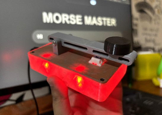
Morse Master
Greetings everyone, and welcome back.
Morse code, a timeless art form, continues to be revered for its ingenuity and history. Imagine developing a device that bridges the gap between traditional communication methods and current technologies.
Meet Morse Master, a Morse Code translator that can be controlled with a sleek web app or a tactile push button. The Morse Master goes beyond utility by combining interactive LED displays, Wi-Fi connectivity, and manual input choices in a single attractive design.

This device is powered by the Raspberry Pi PICO W Dev Board, allowing us to connect it to the internet. We created a webapp that allows users to enter any message, which is subsequently translated and outputted via the four 5mm LEDs linked to the Raspberry Pi pico W.
Furthermore, we have included a mechanical switch on this device that allows us to manually enter the morse code.
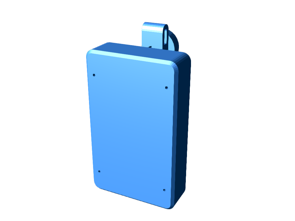
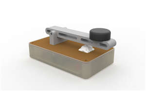
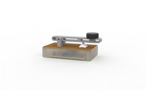
We designed the 3D model of Morse master in Fusion 360, borrowing inspiration from real Morse Key devices used to type Morse code. The idea here was to create a device that could be easily 3D printed and assembled.
Using one of our previously designed Raspberry PI PICO Expansion board PCBs from a previous project, we used the custom board to create a simple Raspberry Pi PICO W and 5mm LED setup that would be used to display Morse code via RED LEDs.
This whole article is about the build process of this Morse Master device, so let's get started with the build.
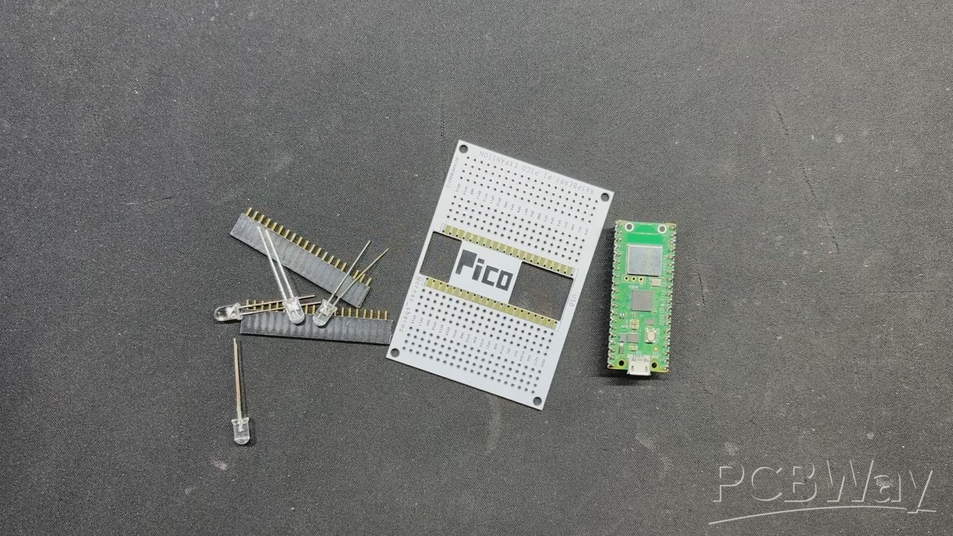
MATERIALS REQUIRED
These are the materials used in this build:
- Raspberry Pi PICO W
- Custom PICO Expansion Board PCB
- Header Pins
- 5mm RED LED
- 3D Printed Parts
- M2 Screws
- M3 Bolt
- DC Barrel Jack
MORSE CODE—History and Facts

The Morse code was created in the early 1830s by Samuel Morse, an American artist and inventor, and his collaborator Alfred Vail. It was initially developed as a way to send communications over large distances using the telegraph, a revolutionary communication instrument at the time.
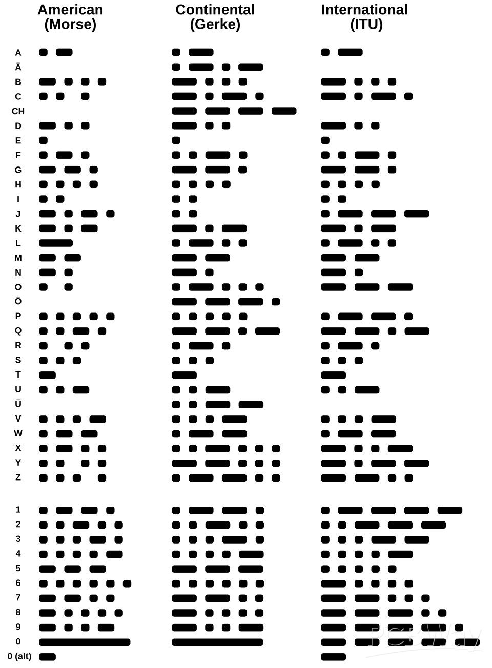
The first version, known as "American Morse Code," employed dots and dashes to represent letters, numerals, and punctuation.
In 1851, a more standardized form known as the "International Morse Code" was established to incorporate non-English characters and diacritical markings, making it appropriate for global use. This form became the universal norm, and it is still acknowledged today.
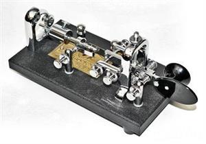
The Morse key, also referred to as a telegraph key, was a device for manually transmitting Morse code signals via telegraph lines. It consisted of a lever that could be depressed to complete an electrical circuit, letting current to flow and provide a signal. Operators would press the key to create short signals (dots) and hold it down for long signals (dashes). These messages were sent as electrical pulses across telegraph cables to a receiver, where they were decoded into letters, numbers, and symbols.
The Morse key required aptitude and precision since operators had to keep consistent timing for dots, dashes, and gaps between characters and sentences. Experienced telegraphers may convey messages at astounding rates, generally measured in words per minute. The device was widely employed in communication systems, particularly in railways, maritime operations, and military settings, where it played an important role in transmitting critical information rapidly and reliably. Over time, the Morse key came to represent early telecommunications and the era's innovation.
DESIGN

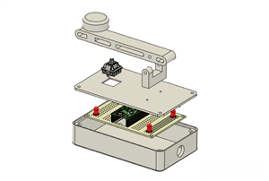
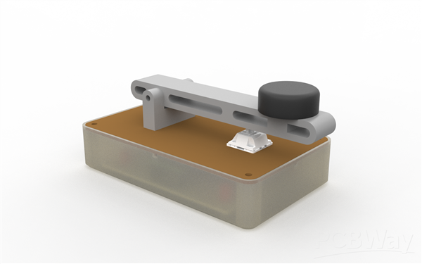
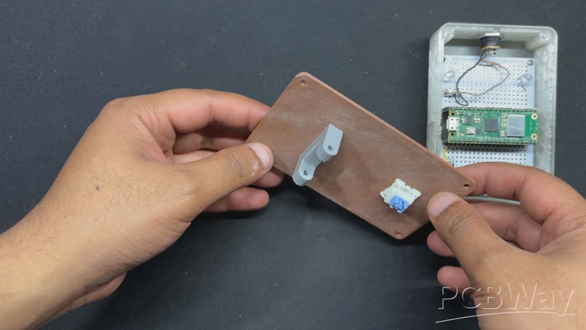
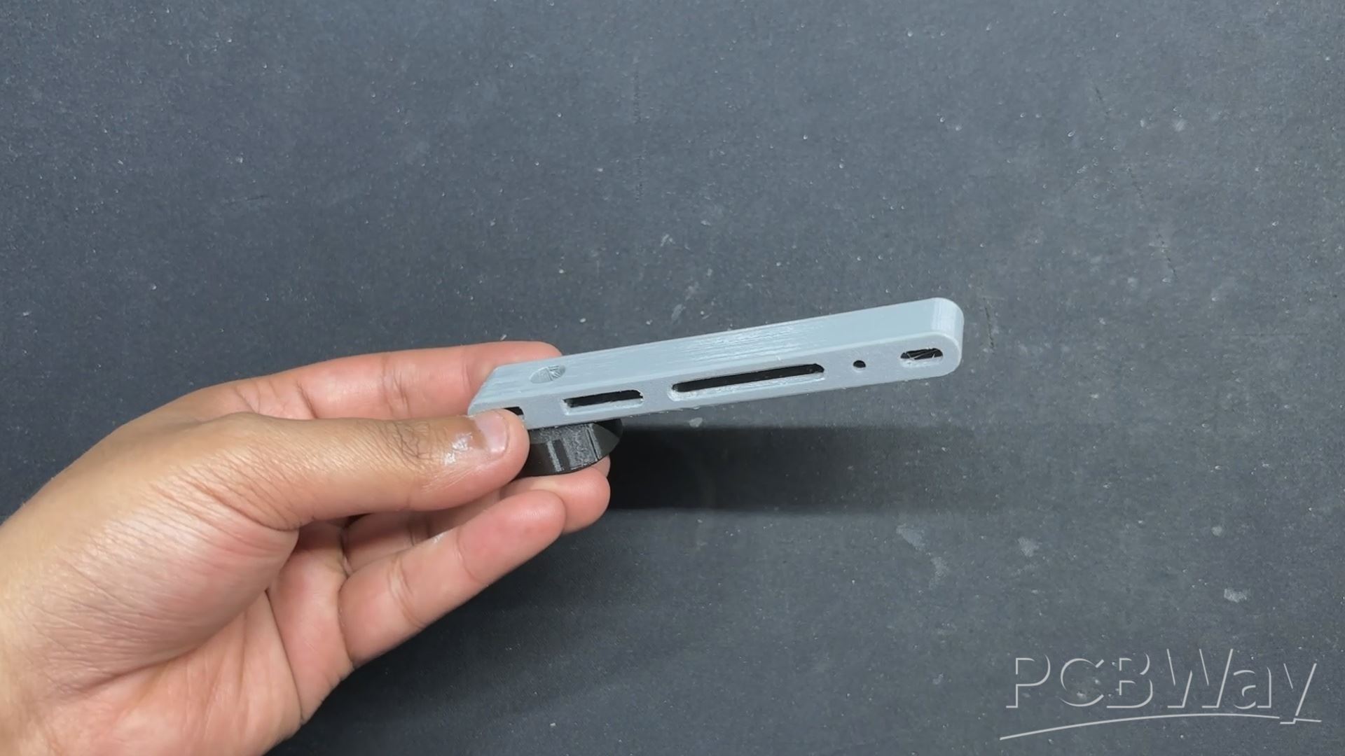
We modeled our design after the Morse key, creating an enclosure that holds the Pico W circuit within; this comprises of a main body and a lid, to which we have attached a lever holder.
We included a lever alongside the Lever holder, and on one side of the lever, we included a knob similar to the one found on a Morse key, which allows the user to correctly grip the lever and operate the device.
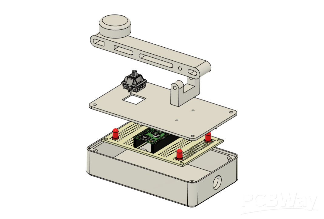
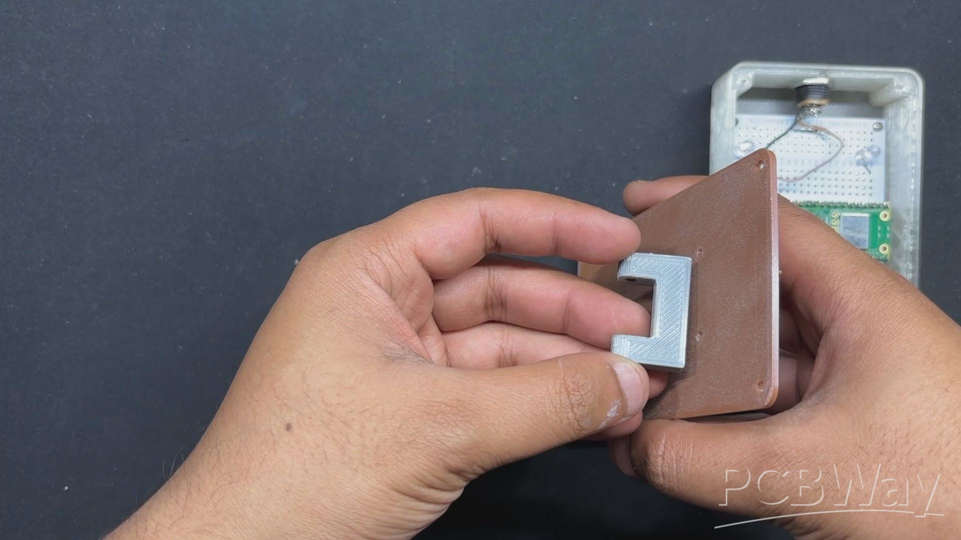
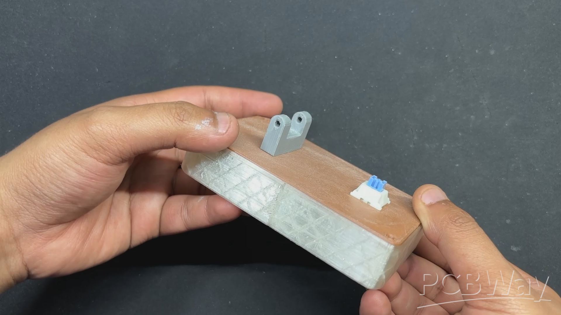
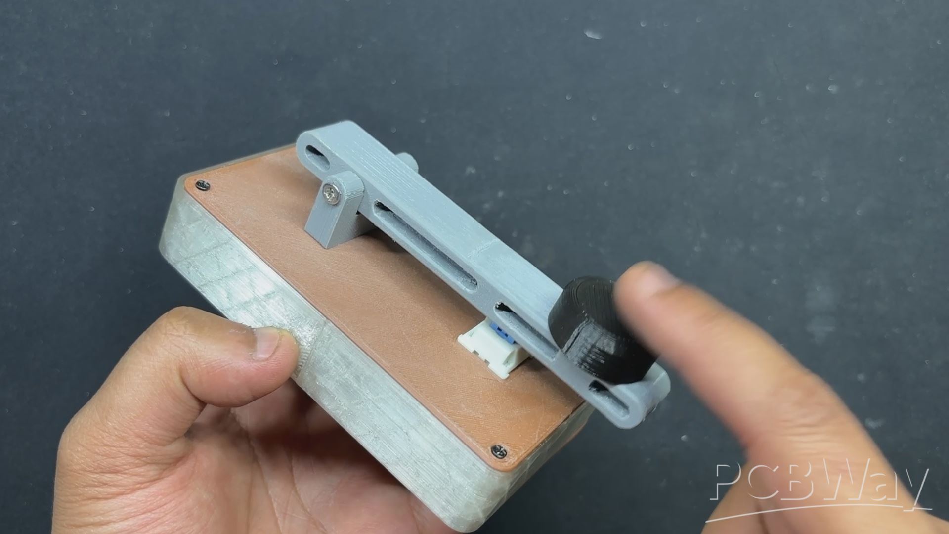
A mechanical Blue Switch has been added to the Lid part, and the Lever is positioned above the Mechanical Switch; when the lever is pressed down, the switch toggles, and a switch press is registered by the PICO W.
To hold the mechanical switch in place, we built a square opening in the lid; the mechanical switch slides into this slot and is kept in place with two locks on its body. These two locks enabled us to securely hold the switch in place on the lid section.
The circuit is mounted inside the main body and held in place with four M2 screws, each with its own screw boss.
Regarding the design of the lid section and main body assembly, we have added four screw holes in each corner, as well as four screw bosses next to each screw hole. We'll be using four M2 screws here as well.
To secure the lever to the lever holder, we just use a Long 30mm M3 Bolt.
Our design follows the design language of prior Morse Keys that have been used in the past.
We printed the main body with transparent PLA to diffuse the red color glow. The lid part was printed with brown PLA, the lever and lever holder were printed with grey PLA, and the knob was printed with black PLA.
RASPBERRY PI PICO W SETUP

The Raspberry Pi Pico W, a compact and versatile microcontroller that adds wireless connectivity to the already popular Pico series, will be used as the project's brain. It is powered by the Raspberry Pi's RP2040 chip and has a dual-core Arm Cortex-M0+ processor that can run at up to 133 MHz, making it both efficient and powerful for a variety of applications. This microcontroller, which includes built-in 2.4 GHz Wi-Fi, was ideal for our Morse Code Translator devices project, which utilizes a WEB APP.
https://www.raspberrypi.com/documentation/microcontrollers/pico-series.html
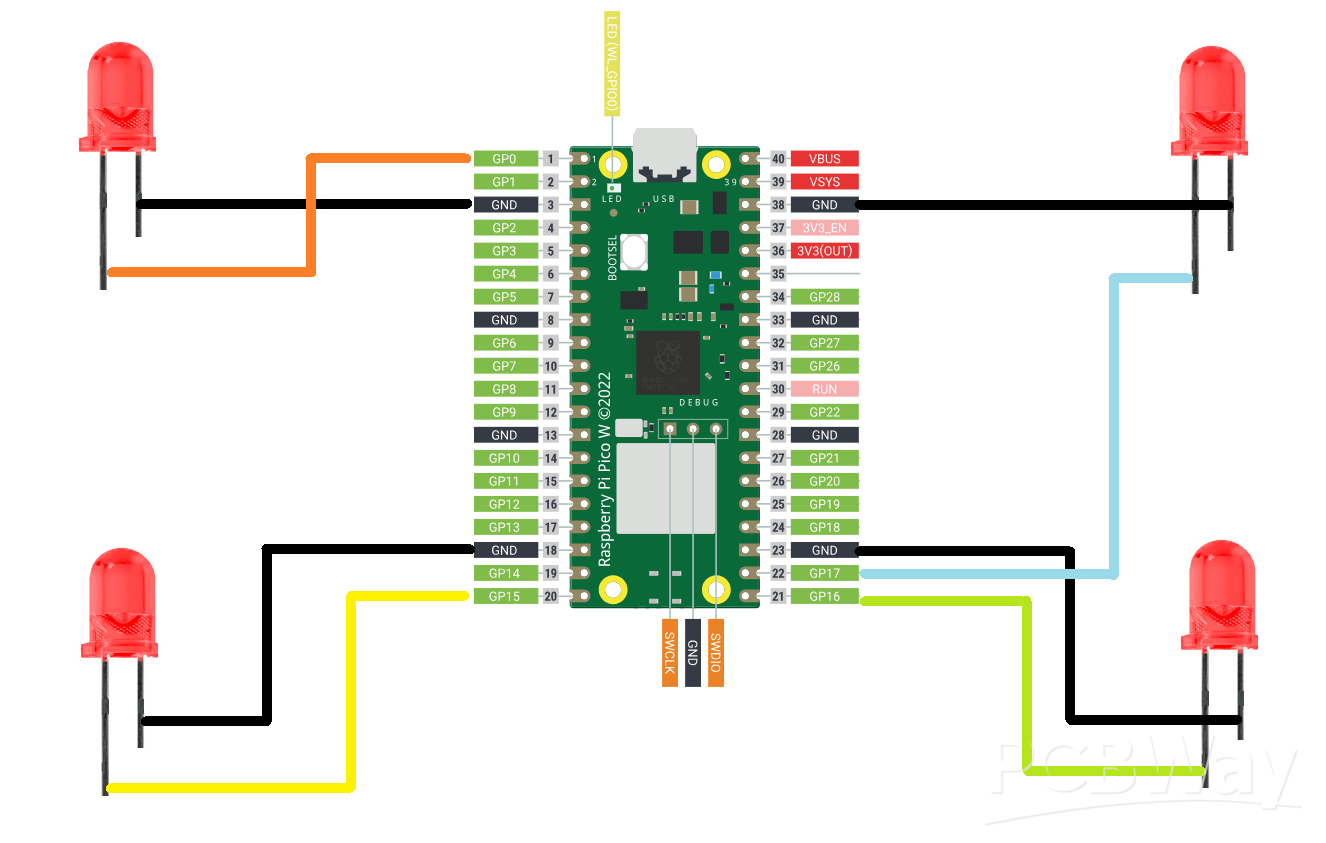
We coupled the PICO W with our previously created PICO Expansion board, which breaks out all of PICO's GPIO pins and adds extra pins that may be used to pair sensors and other electronic devices with PICO. In our case, we added four 5mm RED LEDs to PICO W's GPIO pins.
The anode of the LEDs is linked to GPIO0, GPIO15, GPIO16, and GPIO17, while the cathode of all LEDs is connected in parallel and then coupled with the GND of PICO W.
PCBWAY SERVICE

Let's have a look at the Expansion Board PCB which was designed from scratch and then sent to PCBWAY for samples.
Expansion board order was placed for White Soldermask and Black silkscreen.
After placing the order, the PCBs were received within a week, and the PCB quality was pretty great.
Their commitment to quality and customer satisfaction has been unwavering, leading to significant growth and expansion.
Also, PCBWAY is organizing a PCB badge-making competition to mark their 11th anniversary, inviting designers and makers to showcase their creativity by designing badges that celebrate the company's legacy and envision a bold future. Participants must incorporate the elements "PCBWay" and the number "11" in their designs and can use PCB, PCB+SMT/THT, or PCB+3D printing techniques. Submissions can be posted in the comments, emailed, or shared on social media with the hashtag #PCBWay11BadgeContest.
Prizes include cash, PCBway coupons, and free prototyping services for all qualifying entries.
You guys can check out PCBWAY if you want great PCB service at an affordable rate.
BOARD ASSEMBLY
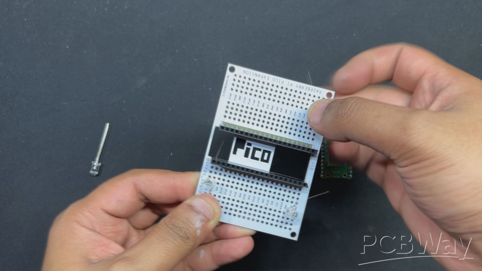
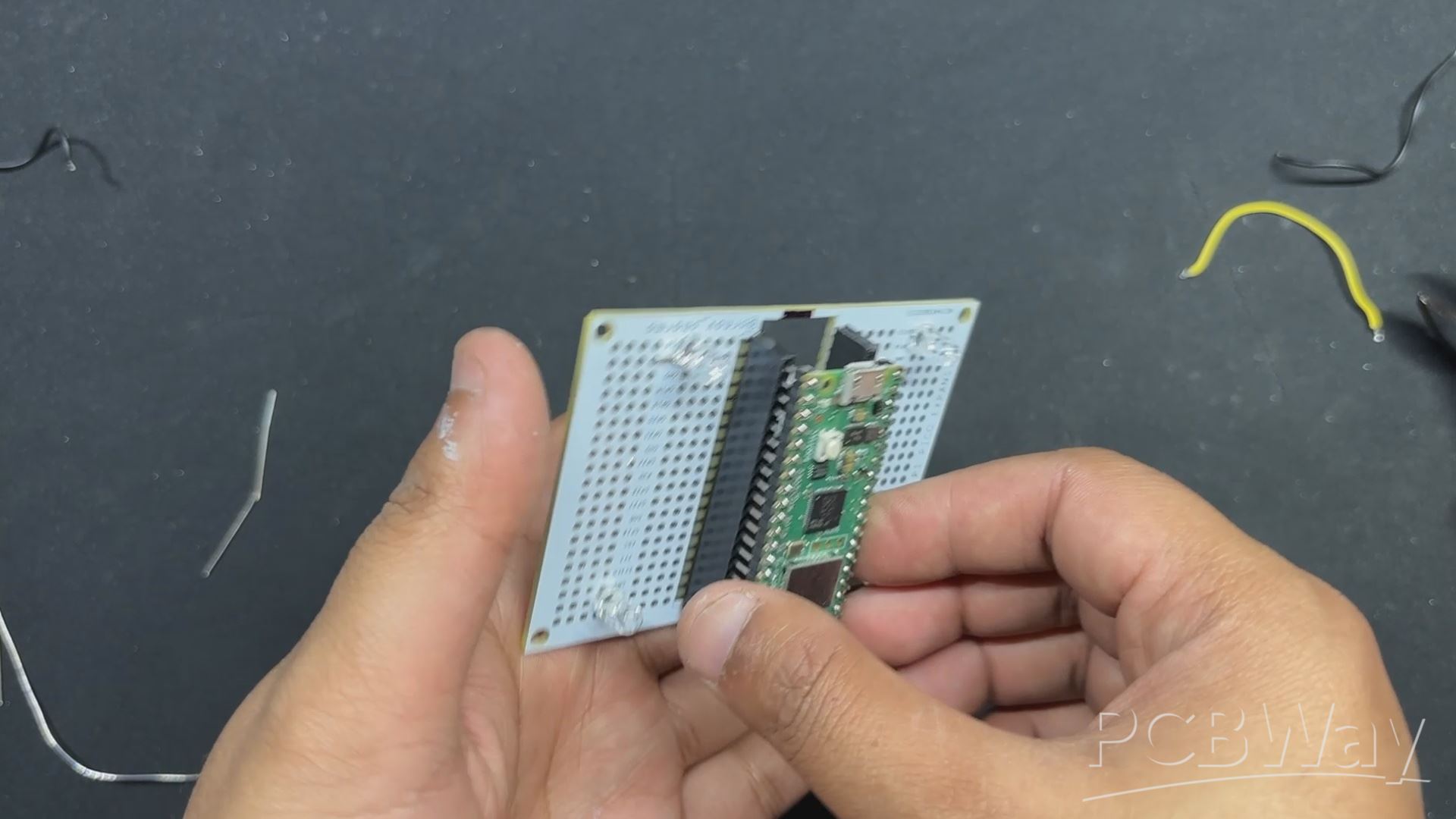
- The board assembly process begins with the installation of two CON20 Female header pin connectors in place of PICO W. We will use these header pin connectors in place of PICO.
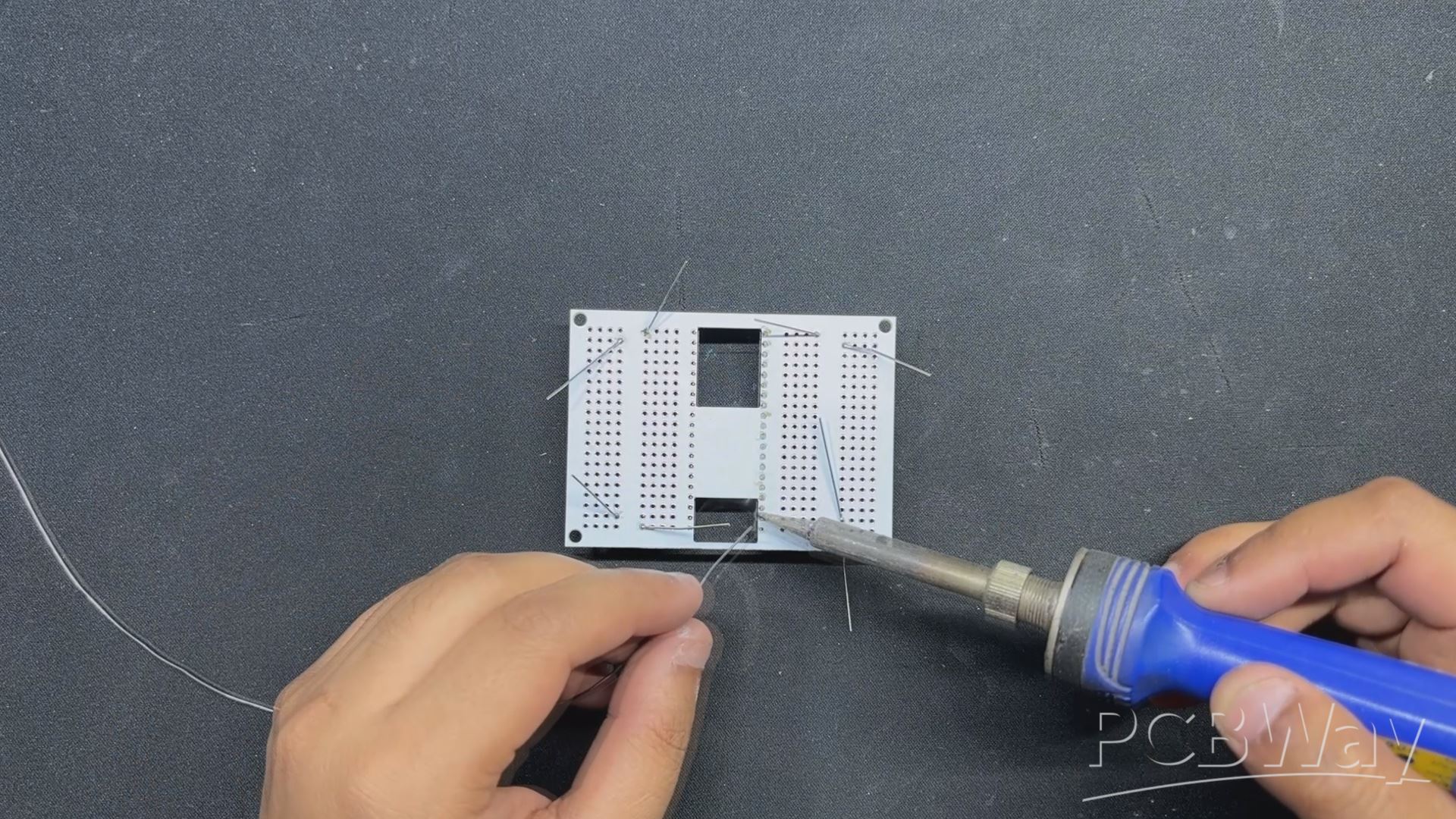
- Next, we place four 5mm LEDs near each corner of the expansion board.
- By flipping the board over, we use a soldering iron to solder each through-hole pad, securing all THT components in place.
- Using pliers, we align the excess legs of a 5mm LED and attach them to the PICO GPIO pins. We built connections and linked all of the LED anode pins to GPIO0, GPIO15, GPIO16, and GPIO17. The cathode of all LEDs is linked to GND.
- After finishing the soldering, we installed PICO W over the CON20 header pin connector.
TEST SKETCH
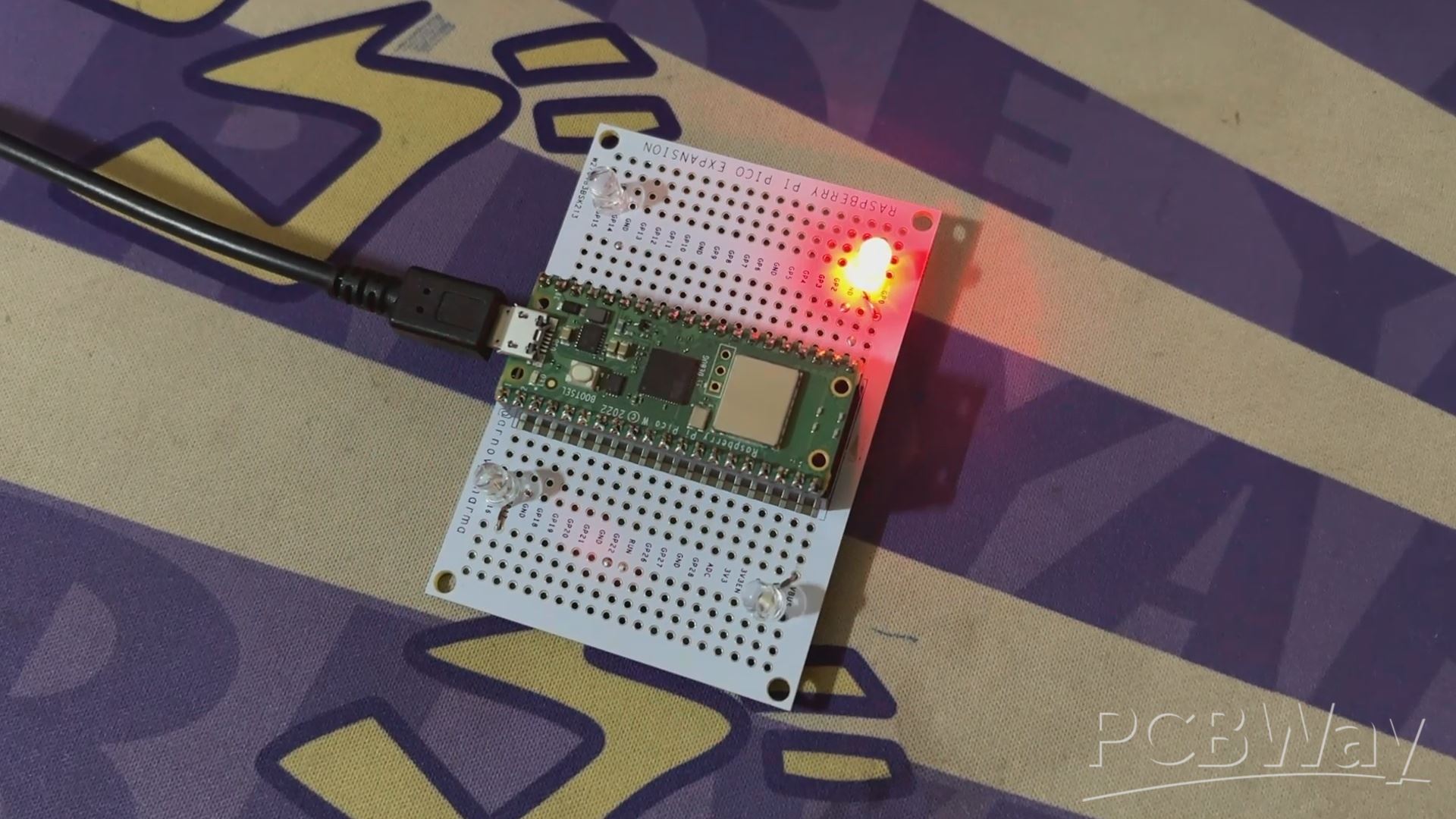
For testing the LEDs, we uploaded a Sample Chaser sketch to our PICO W, which turns ON and OFF each LED in a Chaser Sequence in a Loop.
// Define the GPIO pins for the LEDs const int ledPins[] = {0, 15, 16, 17}; const int numLeds = sizeof(ledPins) / sizeof(ledPins[0]); void setup() { // Initialize each LED pin as an output for (int i = 0; i < numLeds; i++) { pinMode(ledPins[i], OUTPUT); digitalWrite(ledPins[i], LOW); // Make sure LEDs are off initially } } void loop() { // Iterate through each LED, turning it ON and then OFF in sequence for (int i = 0; i < numLeds; i++) { digitalWrite(ledPins[i], HIGH); // Turn ON the current LED delay(200); // Wait for 200 milliseconds digitalWrite(ledPins[i], LOW); // Turn OFF the current LED } }
After making sure that our Setup is working electrically, let's move to the assembly process.
BUTTON ASSEMBLY
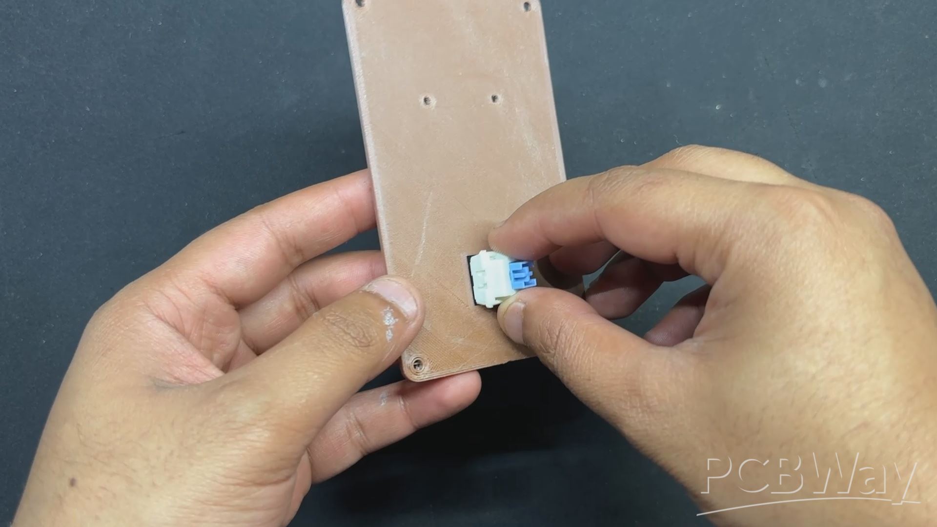
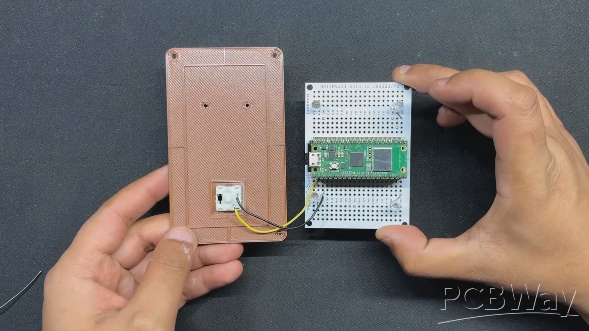
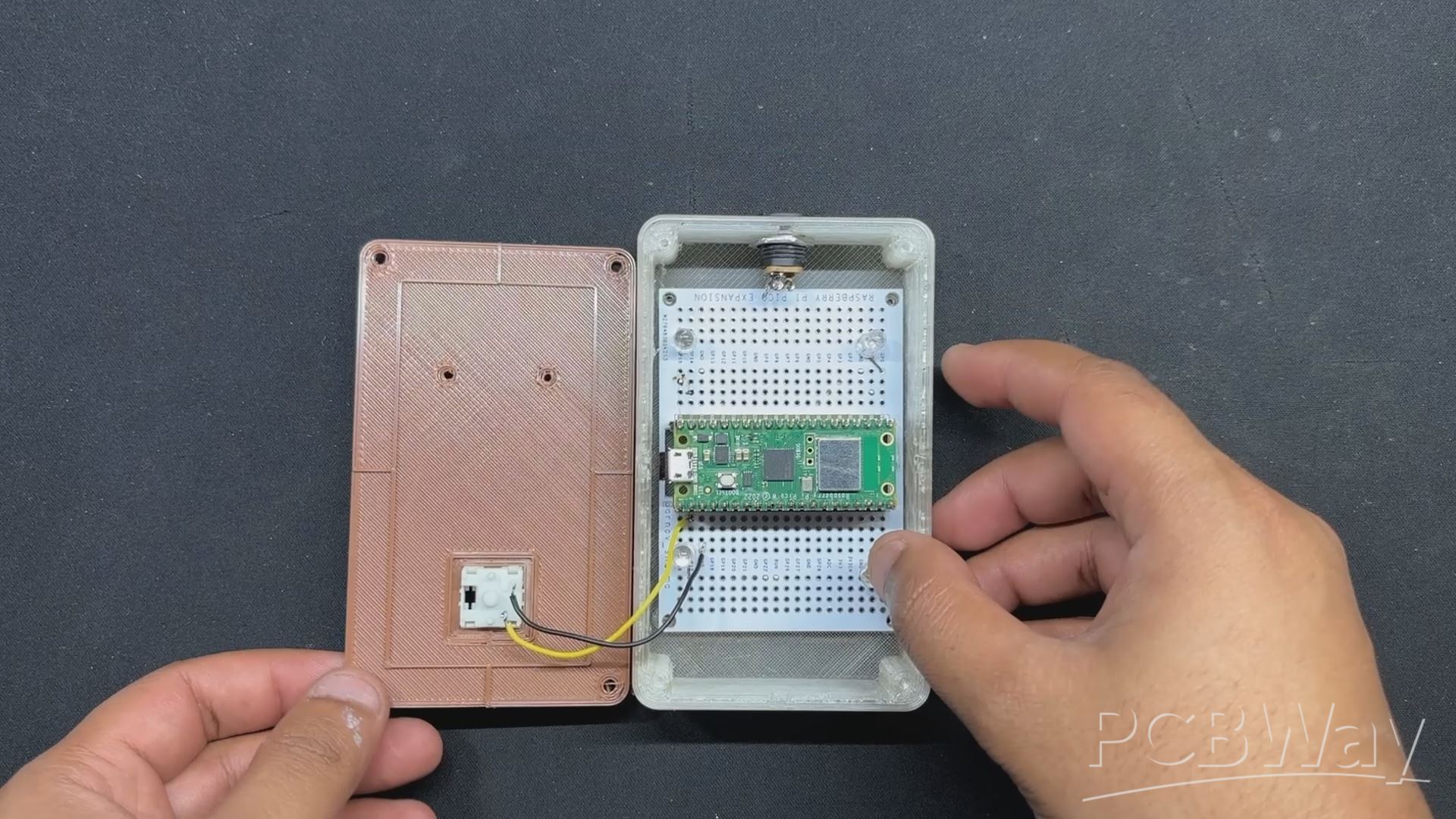
- We place the mechanical switch in its slot on the lid section, pushing it downwards to secure it in place.
- Next, we solder wires from GPIO1 to one terminal of the switch, while the other terminal is linked to the GND terminal.
DC JACK ASSEMBLY
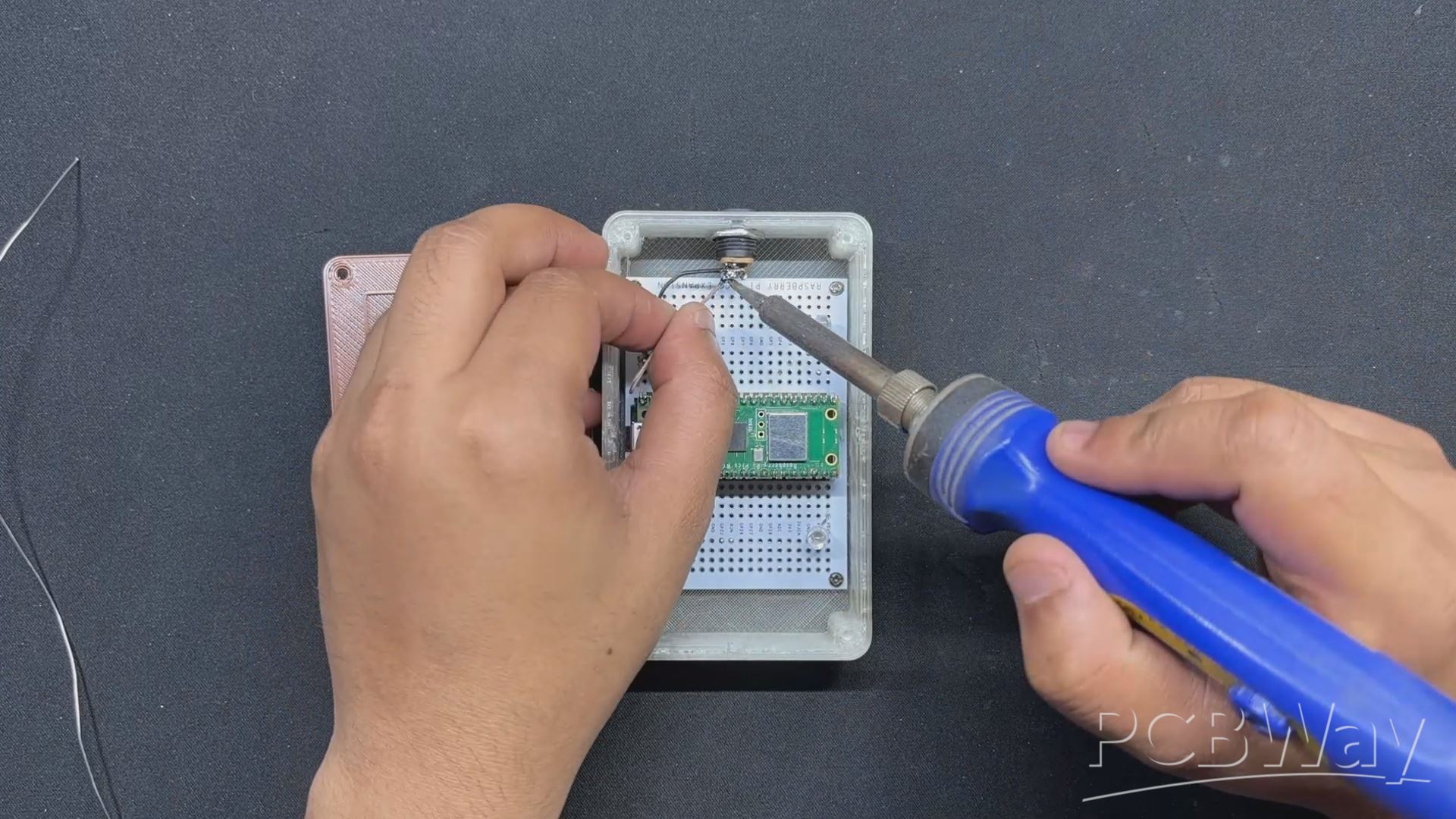
DC barrel The jack is then inserted in its mounting hole on one face of the main body and fastened in place with its nut.
BASE BODY & LID ASSEMBLY
- The PICO W Circuit is then installed within the Main body, over four screw bosses, and tightened with four M2 screws.
- Next, we connected two wires to the PICO's VBUS and GND terminals, then connected the VBUS wire to the DC jack's VCC and the GND wire to the DC jack's ground.
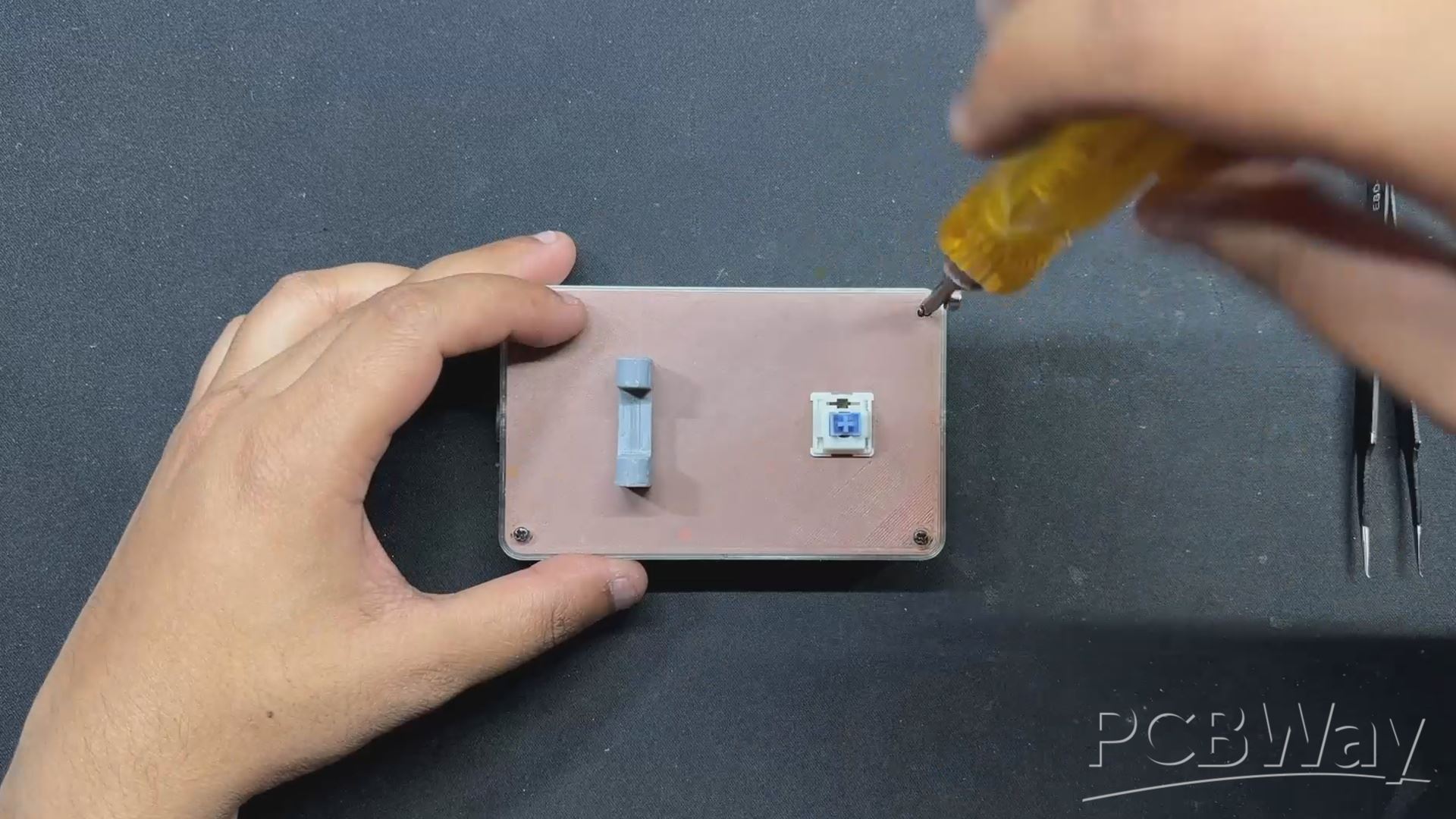
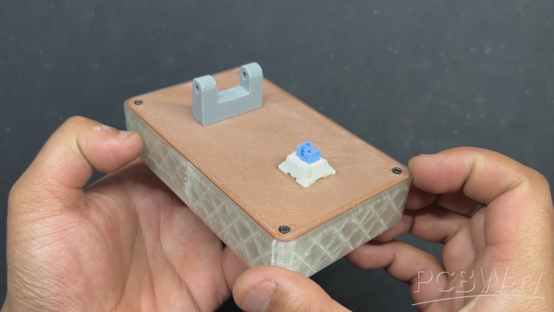
- We then install the lever holder on top of the lid by aligning the mounting holes and secure both of them with two m2 screws.
- The Lid Part is then installed from the top side of the Main Body, and four m2 screws are used to attach both of them together.
LEVER ASSEMBLY
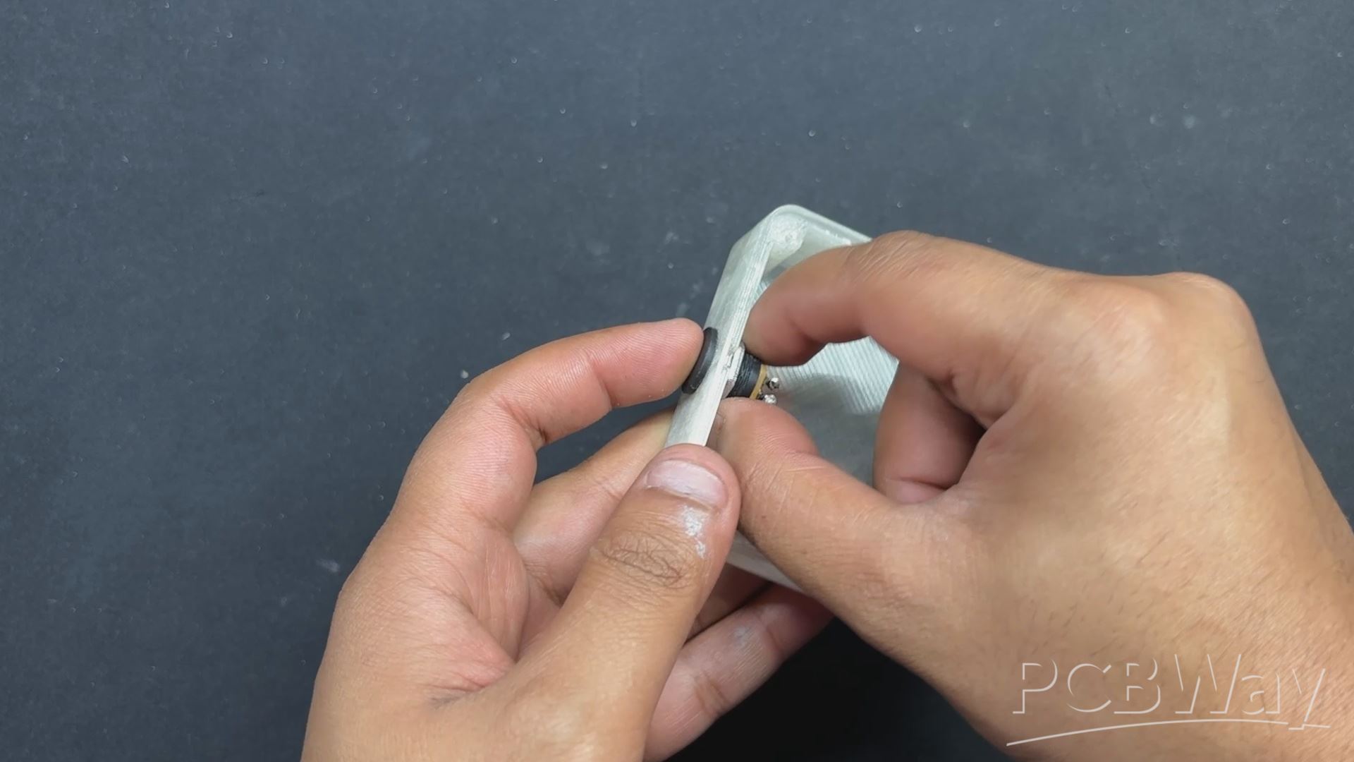
For the Lever Assembly, we placed the 3D Printed Knob over the lever and secured it with an M2 screw.
FINAL ASSEMBLY
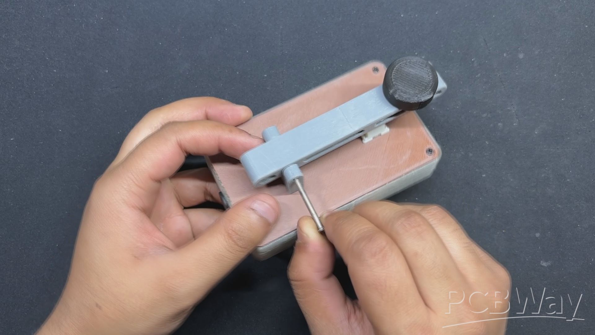
- For the final assembly, the lever is attached to the lever-holding part, and a Long M3 Bolt is utilized to connect them both.
- We tighten the M3 bolt with a secure driver, and the assembly is now complete.
POWER SOURCE
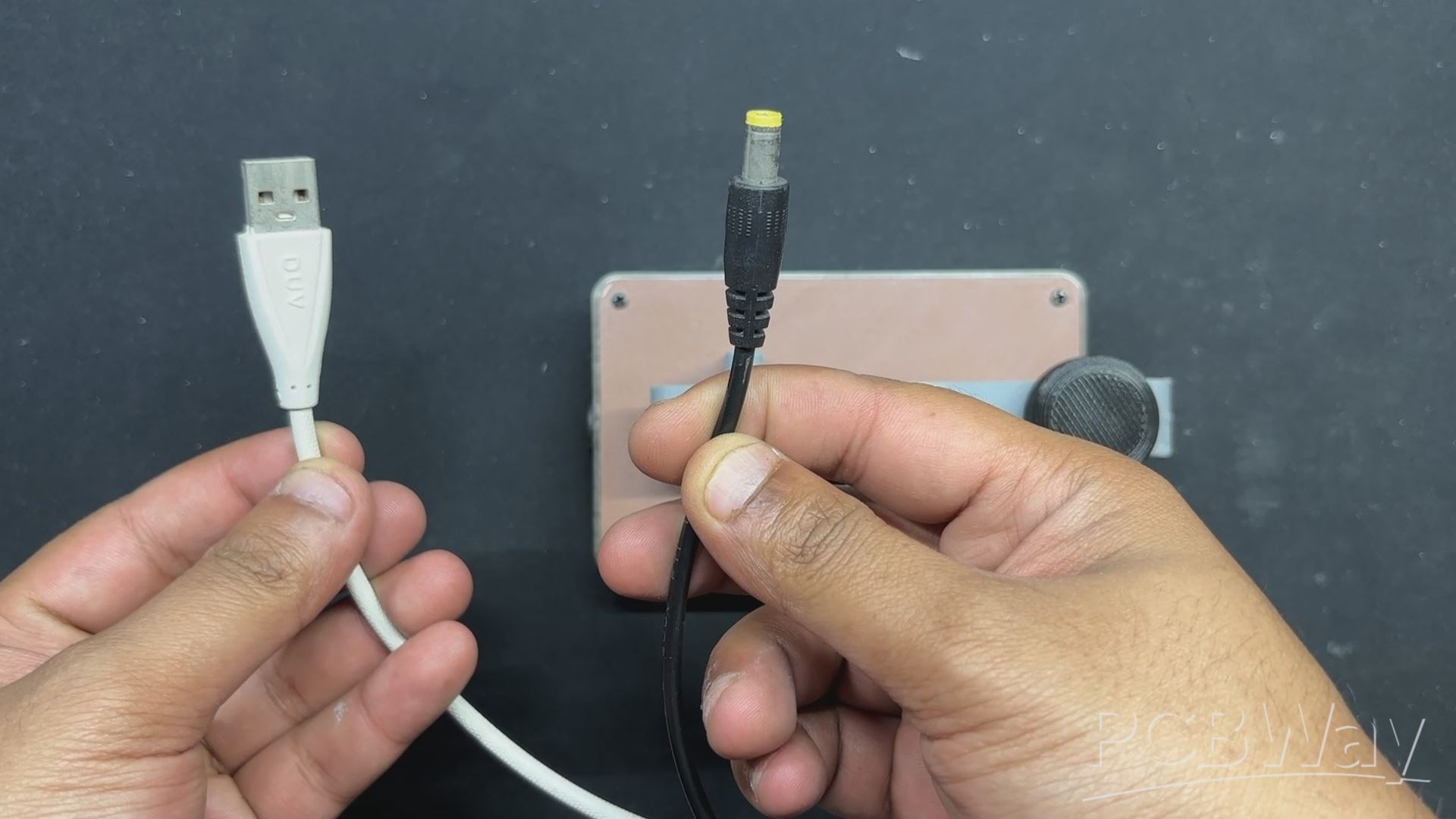
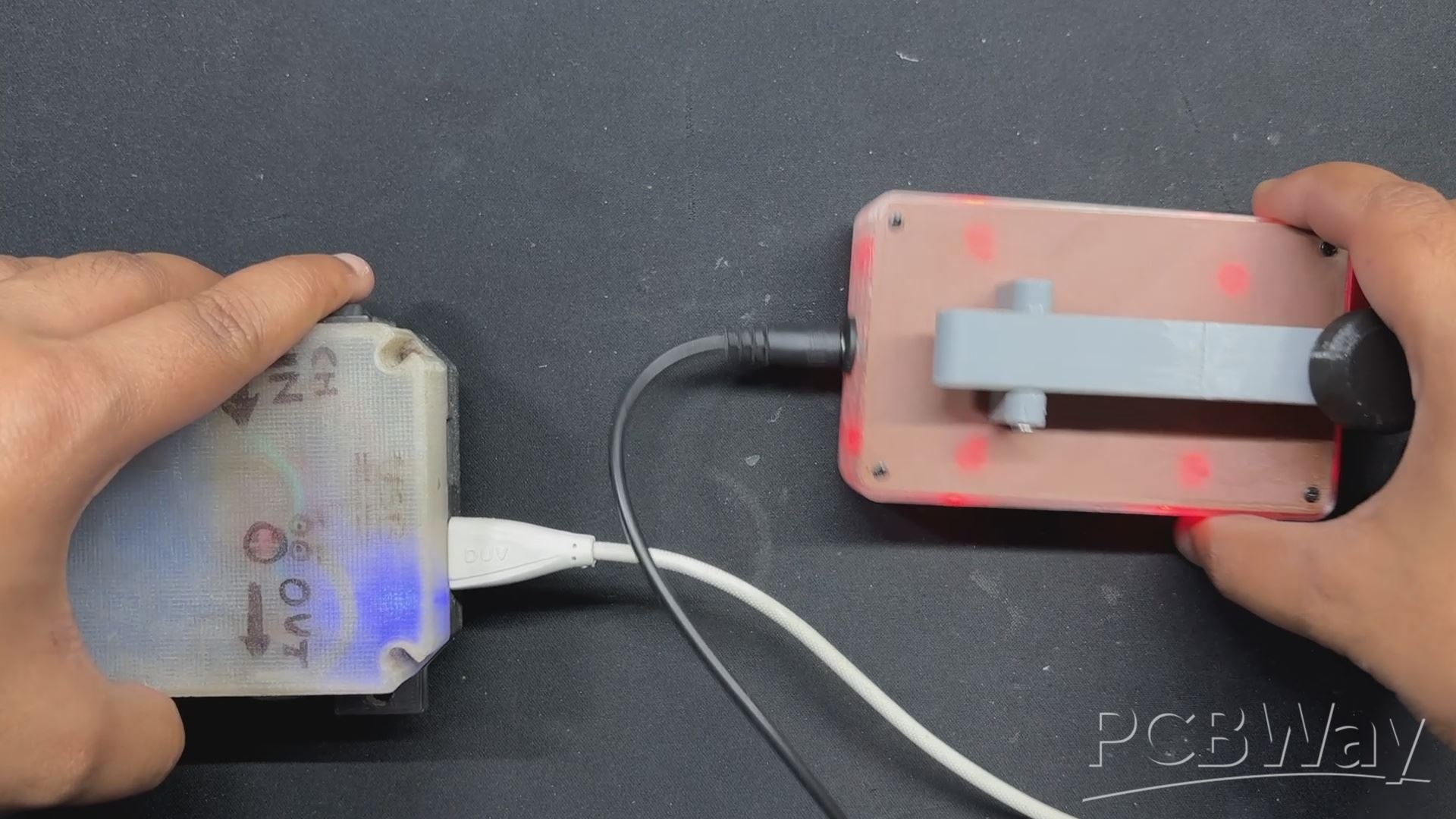
For the power source, we will use a 5V power bank, and to connect the power bank's 5V to our device, we will use a modified USB cable. One end of the cable will have a regular USB port, and the other end will have a barrel jack connector with 5V of USB linked with the barrel jack's 5V and GND to ground.
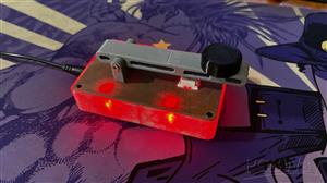
RESULT
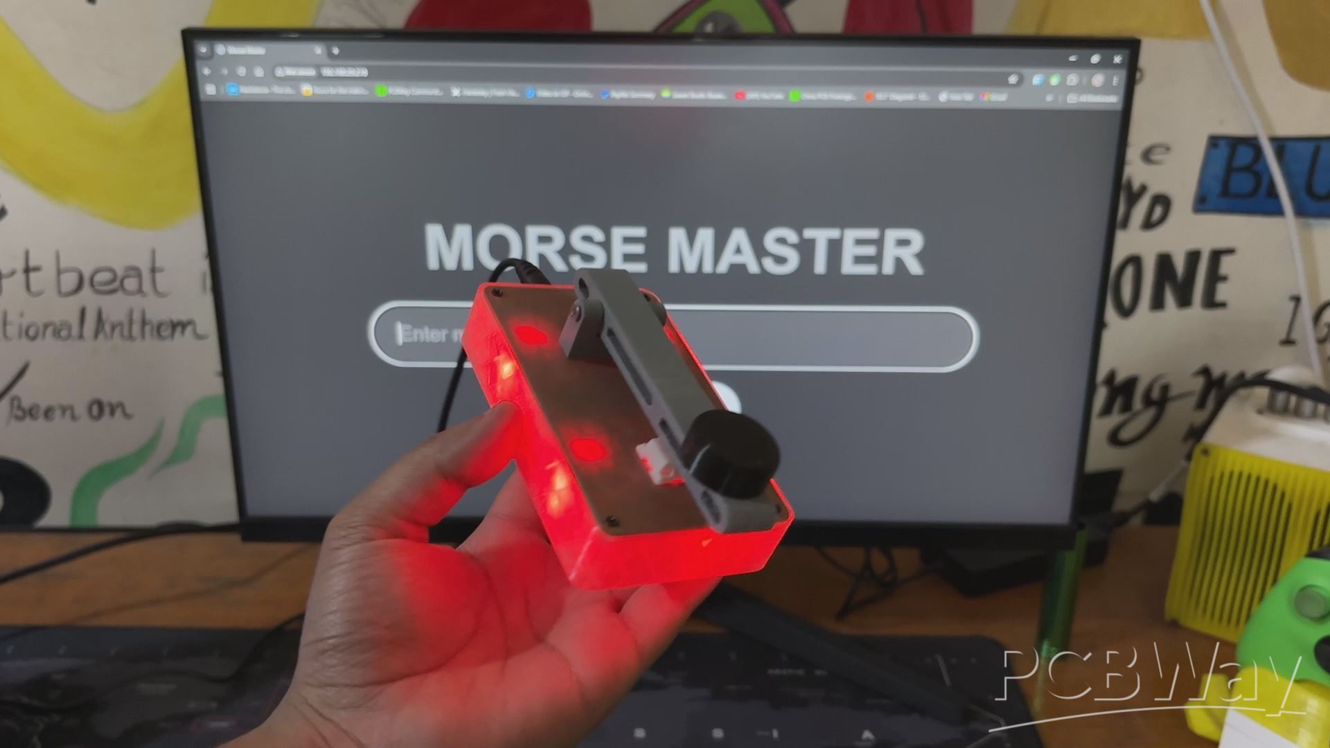
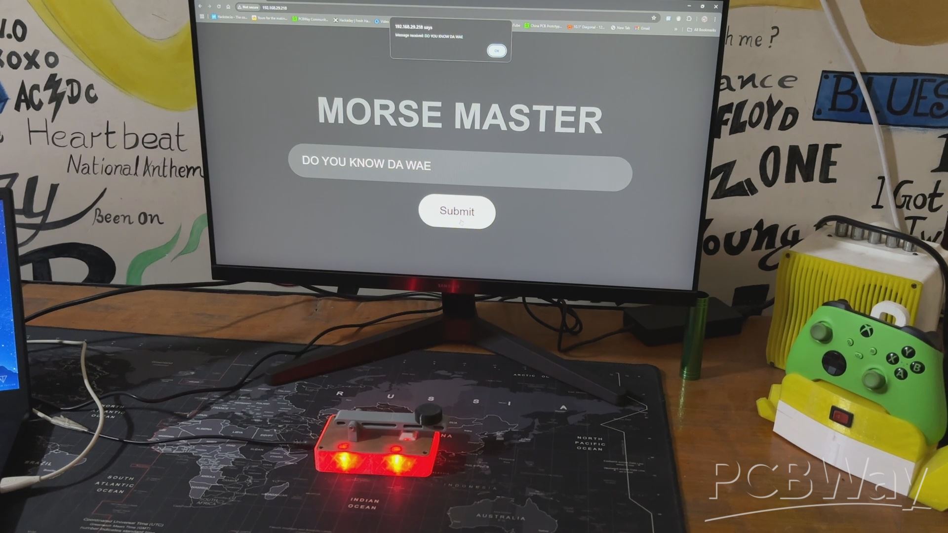
The ultimate result of this Build is a Functional Morse Code Translator device that can be operated via a web app or by using the onboard Key Mechanism to input Morse code, which will be displayed via the LED.
Using this device, one can access the webpage and translate whatever message he wants by entering the message into the Enter Message Bar and then clicking the Submit button, which will start the translation process. LED blinks in response to each letter Morse code.
MORSE CODE TRANSLATION
Let's have a look at some of the alphabets we attempted inputting into the website. We'll start with the letter A, which is represented by a dot followed by a dash. In our case, a short Blink (dot) is immediately followed by a longer Blink (dash).
Next, we tried Letter B, which is represented by a dash followed by three dots. In our example, it begins with a longer Blink (dash), followed by three short Blinks (dots) in rapid succession.
We then entered Letter C, which consists of a dash, a dot, another dash, and a final dot. In our case, the sequence would be a long blink (dash), a short blink (dot), another long blink (dash), and finally a short blink (dot).
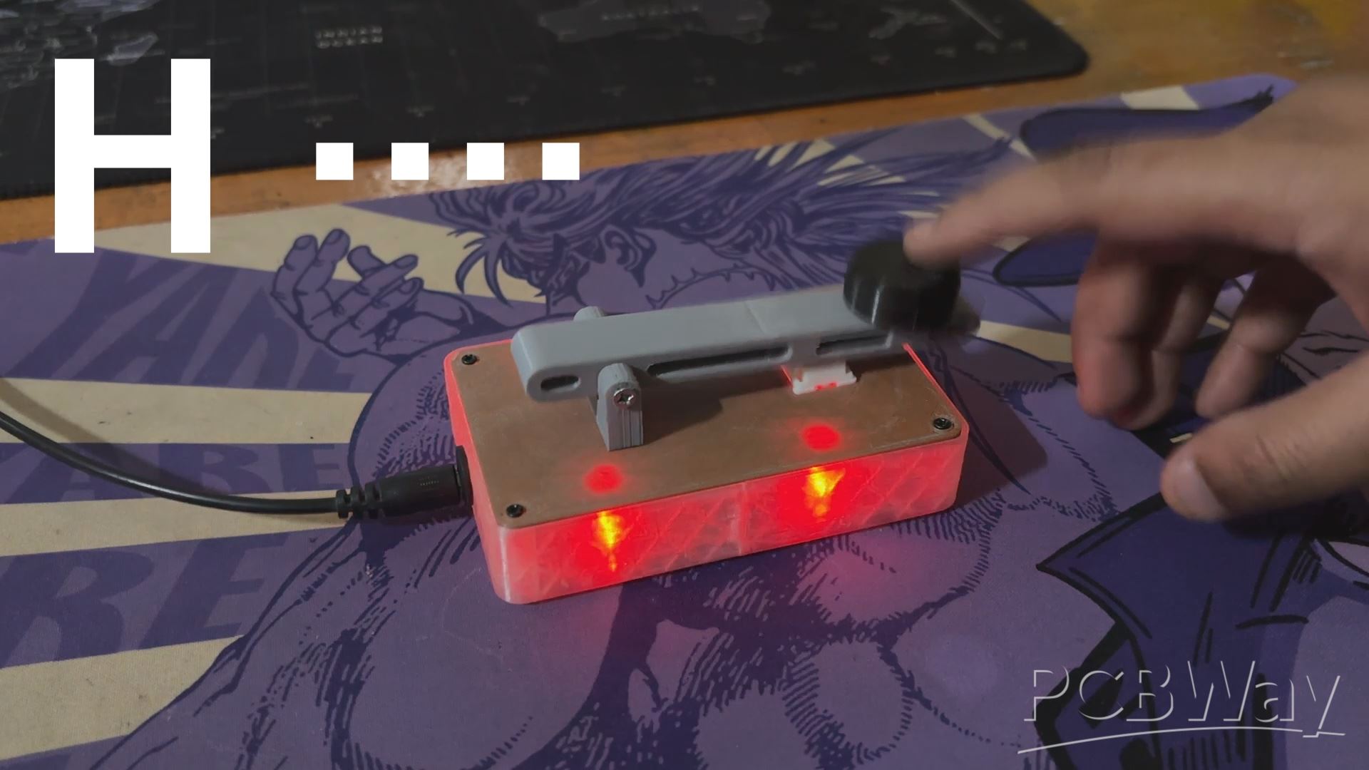
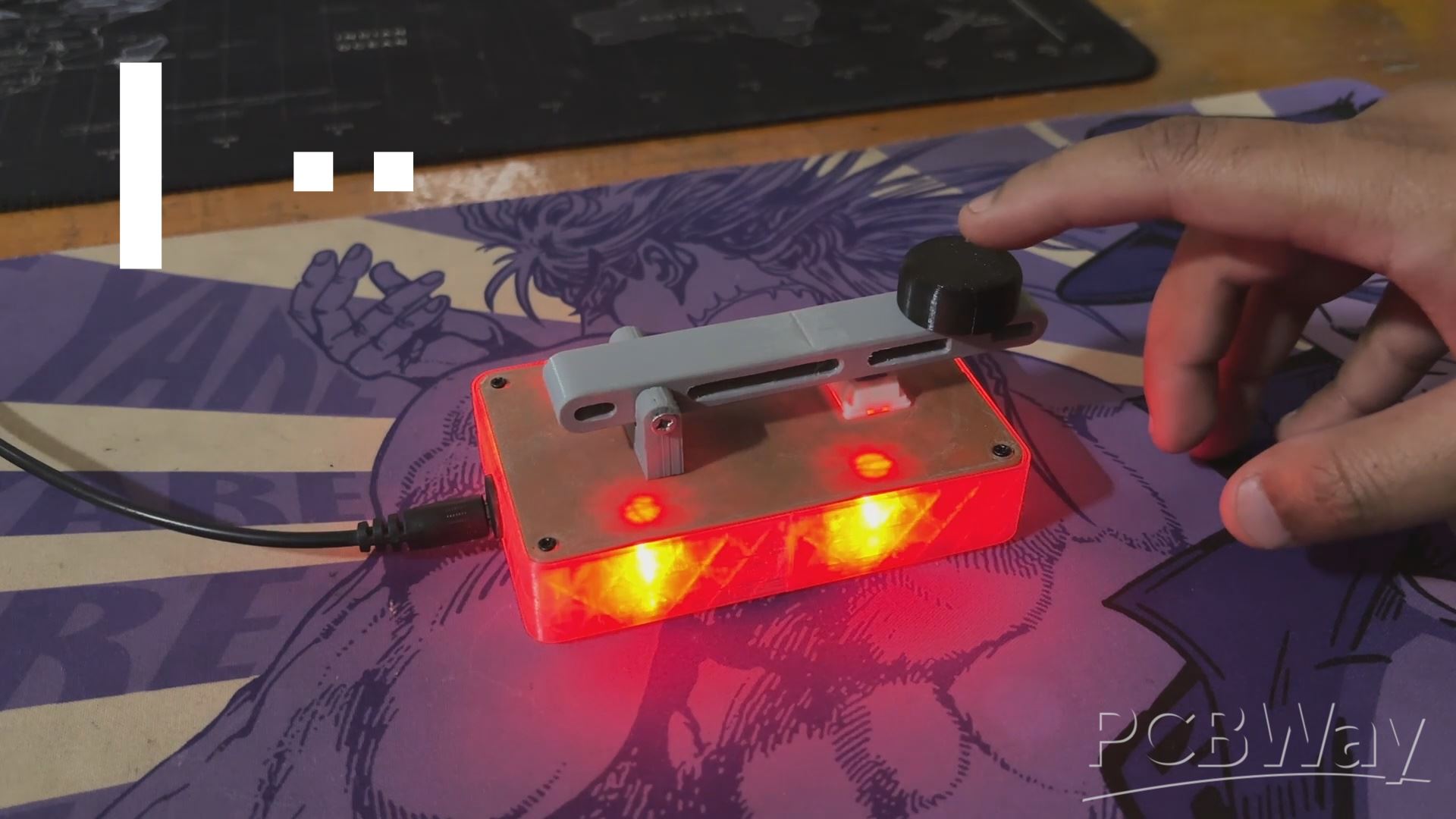
After mastering the code, we were able to pronounce HI in Morse code, which consists of H (four rapid blinks) followed by I (two quick blinks), with tiny intervals between each blink and a somewhat longer break between the two letters.
This device allows you to translate sentences, characters, and alphabets into Morse code by accessing the WEB PAGE or manually entering the Morse code using the onboard Morse key configuration.
Please let me know if you require any additional assistance; all the documents, files, and code are included in the article.
In addition, we appreciate PCBWAY's support of this project. Visit them for a variety of PCB-related services, such as stencil and PCB assembly services, as well as 3D printing services
Thanks for reaching this far, and I will be back with a new project pretty soon.
Peace.
#include <WiFi.h>
#include <WebServer.h>
// Replace with your Wi-Fi credentials
const char* ssid = "YOUR SSID";
const char* password = "YOUR PASS";
// Set up GPIO pins
const int LED_PINS[] = {0, 15, 16, 17}; // Array of GPIO pins for LEDs
const int BUTTON_PIN = 1;              // Push button for manual input
// Morse code timings
const int dotDuration = 200;    // Duration of a dot in milliseconds
const int dashDuration = 600;   // Duration of a dash in milliseconds
const int pauseDuration = 200;  // Pause between symbols
const int wordPause = 800;      // Pause between words
const int buttonThreshold = 500; // Threshold for differentiating dot/dash
// Web server instance
WebServer server(80);
String morseMessage = "";
// Morse code dictionary (simplified)
String translateToMorse(char c) {
switch (toupper(c)) {
case 'A': return ".-";
case 'B': return "-...";
case 'C': return "-.-.";
case 'D': return "-..";
case 'E': return ".";
case 'F': return "..-.";
case 'G': return "--.";
case 'H': return "....";
case 'I': return "..";
case 'J': return ".---";
case 'K': return "-.-";
case 'L': return ".-..";
case 'M': return "--";
case 'N': return "-.";
case 'O': return "---";
case 'P': return ".--.";
case 'Q': return "--.-";
case 'R': return ".-.";
case 'S': return "...";
case 'T': return "-";
case 'U': return "..-";
case 'V': return "...-";
case 'W': return ".--";
case 'X': return "-..-";
case 'Y': return "-.--";
case 'Z': return "--..";
case ' ': return " ";
default: return ""; // Ignore unsupported characters
}
}
// Function to initialize LEDs
void initializeLEDs() {
for (int i = 0; i < 4; i++) {
pinMode(LED_PINS[i], OUTPUT);
digitalWrite(LED_PINS[i], HIGH); // Ensure LEDs are ON initially
}
}
// Function to set the state of all LEDs
void setLEDState(bool state) {
for (int i = 0; i < 4; i++) {
digitalWrite(LED_PINS[i], state ? HIGH : LOW); // Set LEDs ON or OFF
}
}
// Function to blink LEDs for Morse code
void blinkMorse(String morseCode) {
for (int i = 0; i < morseCode.length(); i++) {
char c = morseCode[i];
if (c == '.') {
setLEDState(false); // Turn LEDs OFF
delay(dotDuration);
setLEDState(true); // Turn LEDs ON
delay(pauseDuration);
} else if (c == '-') {
setLEDState(false); // Turn LEDs OFF
delay(dashDuration);
setLEDState(true); // Turn LEDs ON
delay(pauseDuration);
} else if (c == ' ') {
delay(wordPause);
}
}
}
// Updated Function to handle button presses
void manualMorseInput() {
static unsigned long pressStartTime = 0;
static bool buttonPressed = false;
if (digitalRead(BUTTON_PIN) == LOW) { // Button is pressed
if (!buttonPressed) { // Button was not already pressed
pressStartTime = millis();
buttonPressed = true;
}
setLEDState(false); // Keep LEDs off while the button is pressed
} else { // Button is released
if (buttonPressed) { // Only process if button was previously pressed
unsigned long pressDuration = millis() - pressStartTime;
if (pressDuration < buttonThreshold) {
blinkMorse("."); // Short press = dot
} else {
blinkMorse("-"); // Long press = dash
}
buttonPressed = false;
}
setLEDState(true); // Turn LEDs back on when button is not pressed
}
}
// Convert text to Morse and blink it
void displayMorseCode(String text) {
for (int i = 0; i < text.length(); i++) {
String morseCode = translateToMorse(text[i]);
blinkMorse(morseCode);
delay(pauseDuration); // Pause between letters
}
}
// Handle root page
void handleRoot() {
server.send(200, "text/html",
"<!DOCTYPE html>"
"<html>"
// (HTML content omitted for brevity)
"</html>");
}
// Handle message submission
void handleSend() {
if (server.hasArg("message")) {
morseMessage = server.arg("message");
server.send(200, "text/plain", "Message received: " + morseMessage);
displayMorseCode(morseMessage);
} else {
server.send(400, "text/plain", "Invalid Request");
}
}
void setup() {
Serial.begin(115200);
initializeLEDs(); // Initialize multi-LED setup
pinMode(BUTTON_PIN, INPUT_PULLUP); // Configure the button as input
// Connect to Wi-Fi
WiFi.begin(ssid, password);
Serial.println("Connecting to Wi-Fi...");
while (WiFi.status() != WL_CONNECTED) {
delay(1000);
Serial.print(".");
}
Serial.println("\nConnected to Wi-Fi!");
Serial.print("IP Address: ");
Serial.println(WiFi.localIP());
// Start the web server
server.on("/", handleRoot);
server.on("/send", handleSend);
server.begin();
Serial.println("Web server started!");
}
void loop() {
server.handleClient(); // Handle web server requests
manualMorseInput();    // Monitor button presses for Morse input
}

Morse Master
*PCBWay community is a sharing platform. We are not responsible for any design issues and parameter issues (board thickness, surface finish, etc.) you choose.


Raspberry Pi 5 7 Inch Touch Screen IPS 1024x600 HD LCD HDMI-compatible Display for RPI 4B 3B+ OPI 5 AIDA64 PC Secondary Screen(Without Speaker)
BUY NOW


- Comments(0)
- Likes(0)
More by Arnov Arnov sharma
-
 DIY XBOX Controller
Greetings everyone, and welcome back. Here's something fun and custom.This is my version of an Xbox ...
DIY XBOX Controller
Greetings everyone, and welcome back. Here's something fun and custom.This is my version of an Xbox ...
-
 Pocket SNES
Greetings everyone, and welcome back! Today, I’ve got something fun and tiny to share—the Pocket SNE...
Pocket SNES
Greetings everyone, and welcome back! Today, I’ve got something fun and tiny to share—the Pocket SNE...
-
 Batocera Arcade Box
Greetings everyone and welcome back, Here's something. Fun and nostalgic. Right now, we are using ou...
Batocera Arcade Box
Greetings everyone and welcome back, Here's something. Fun and nostalgic. Right now, we are using ou...
-
 64x32 Matrix Panel Setup with PICO 2
Greetings everyone and welcome back.So here's something fun and useful: a Raspberry Pi Pico 2-powere...
64x32 Matrix Panel Setup with PICO 2
Greetings everyone and welcome back.So here's something fun and useful: a Raspberry Pi Pico 2-powere...
-
 Portable Air Quality Meter
Hello everyone, and welcome back! Today, I have something incredibly useful for you—a Portable Air Q...
Portable Air Quality Meter
Hello everyone, and welcome back! Today, I have something incredibly useful for you—a Portable Air Q...
-
 WALKPi PCB Version
Greetings everyone and welcome back, This is the WalkPi, a homebrew audio player that plays music fr...
WALKPi PCB Version
Greetings everyone and welcome back, This is the WalkPi, a homebrew audio player that plays music fr...
-
 Delete Button XL
Greetings everyone and welcome back, and here's something fun and useful.In essence, the Delete Butt...
Delete Button XL
Greetings everyone and welcome back, and here's something fun and useful.In essence, the Delete Butt...
-
 Arduino Retro Game Controller
Greetings everyone and welcome back. Here's something fun.The Arduino Retro Game Controller was buil...
Arduino Retro Game Controller
Greetings everyone and welcome back. Here's something fun.The Arduino Retro Game Controller was buil...
-
 Super Power Buck Converter
Greetings everyone and welcome back!Here's something powerful, The SUPER POWER BUCK CONVERTER BOARD ...
Super Power Buck Converter
Greetings everyone and welcome back!Here's something powerful, The SUPER POWER BUCK CONVERTER BOARD ...
-
 Pocket Temp Meter
Greetings and welcome back.So here's something portable and useful: the Pocket TEMP Meter project.As...
Pocket Temp Meter
Greetings and welcome back.So here's something portable and useful: the Pocket TEMP Meter project.As...
-
 Pico Powered DC Fan Driver
Hello everyone and welcome back.So here's something cool: a 5V to 12V DC motor driver based around a...
Pico Powered DC Fan Driver
Hello everyone and welcome back.So here's something cool: a 5V to 12V DC motor driver based around a...
-
 Mini Solar Light Project with a Twist
Greetings.This is the Cube Light, a Small and compact cube-shaped emergency solar light that boasts ...
Mini Solar Light Project with a Twist
Greetings.This is the Cube Light, a Small and compact cube-shaped emergency solar light that boasts ...
-
 PALPi V5 Handheld Retro Game Console
Hey, Guys what's up?So this is PALPi which is a Raspberry Pi Zero W Based Handheld Retro Game Consol...
PALPi V5 Handheld Retro Game Console
Hey, Guys what's up?So this is PALPi which is a Raspberry Pi Zero W Based Handheld Retro Game Consol...
-
 DIY Thermometer with TTGO T Display and DS18B20
Greetings.So this is the DIY Thermometer made entirely from scratch using a TTGO T display board and...
DIY Thermometer with TTGO T Display and DS18B20
Greetings.So this is the DIY Thermometer made entirely from scratch using a TTGO T display board and...
-
 Motion Trigger Circuit with and without Microcontroller
GreetingsHere's a tutorial on how to use an HC-SR505 PIR Module with and without a microcontroller t...
Motion Trigger Circuit with and without Microcontroller
GreetingsHere's a tutorial on how to use an HC-SR505 PIR Module with and without a microcontroller t...
-
 Motor Driver Board Atmega328PU and HC01
Hey, what's up folks here's something super cool and useful if you're making a basic Robot Setup, A ...
Motor Driver Board Atmega328PU and HC01
Hey, what's up folks here's something super cool and useful if you're making a basic Robot Setup, A ...
-
 Power Block
Hey Everyone what's up!So this is Power block, a DIY UPS that can be used to power a bunch of 5V Ope...
Power Block
Hey Everyone what's up!So this is Power block, a DIY UPS that can be used to power a bunch of 5V Ope...
-
 Goku PCB Badge V2
Hey everyone what's up!So here's something SUPER cool, A PCB Board themed after Goku from Dragon Bal...
Goku PCB Badge V2
Hey everyone what's up!So here's something SUPER cool, A PCB Board themed after Goku from Dragon Bal...
-
Programmable Mist Maker - XIAO / QT PY Extension
172 0 0 -
RadioHAT - Raspberry Pi radio development platform
182 0 1 -
-
-
-
-
ARPS-2 – Arduino-Compatible Robot Project Shield for Arduino UNO
2767 0 5 -
A Compact Charging Breakout Board For Waveshare ESP32-C3
3275 3 8 -
AI-driven LoRa & LLM-enabled Kiosk & Food Delivery System
3529 2 2


