


|
EagleAutodesk
|
|

|
OnShapeOnShape
|
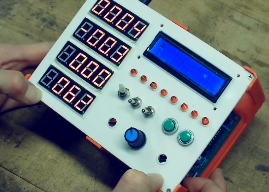
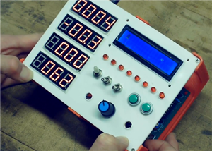
Mars Lander Simulator Panel
Mars Lander Simulator
A physical Mars Lander control panel that runs a simple landing simulation on an 8051-family microcontroller. This repository documents the project, its history, hardware, firmware, and notes.
Quick summary
Hardware: STC125A60S2 (8051 family), 4× seven‑segment displays, 8 LEDs, buttons, potentiometers
Firmware: SDCC (Small Device C Compiler) for 8051
Prototypes:
- Prototype 1 — basic microcontroller + 16×2 LCD (early prototype; see /src/lcd)
- Prototype 2 — finished Dec 2024: full control panel with segmented displays, LEDs, buttons, pots, LCD screen (code in /src/panel)
Video demo: https://youtu.be/TvxShnH4dns?si=FG6ILegN3fnswcwK (see above)
Why I Built This
I built the first prototype in 7th grade to learn microcontrollers, it was just a dev board and a 16×2 LCD. Over time I changed the design, learning about display multiplexing and a tiny real‑time physics loop. The second, upgraded prototype was completed in December 2024 and replaced the LCD with a 4‑digit seven‑segment panel, added LEDs, pots, and buttons for an authentic control‑panel feel.
Highlights / features
- Real-time physics: gravity, thrust, fuel consumption, collision detection, and landing-success criteria.
- Story with sim: real situations (eg. sandstorm) with messages from Houston display on LCD screen. Also has a intro not enabled in video (see above).
- 4× seven‑segment displays for info (altitude, speed, acceleration, fuel/temp).
- 8 LEDs used for warnings/indicators.
- Physical inputs: buttons (on/off, select) and potentiometers (throttle).
- Firmware written in C for an 8051 MCU and compiled with SDCC.
Technical notes
- MCU: STC125A60S2 (8051 derivative from STC)
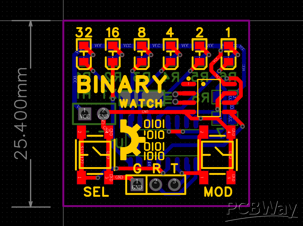
- Seven‑segment: multiplexing (digit transistors + segment bus), current limiting resistors per segment
- Input handling: simple input for buttons; ADC reads for potentiometers; map ADC range to throttle values
- Physics constants: used the actual g (Mars ≈ 3.71 m/s²) and tuned thrust/fuel consumption to make it playable
Lessons learned
- Multiplexed seven‑segment displays are easy on pins but I ran into timing issues. I designed a circuit to cascade two 4017's with only two capacitors. This enabled me to multiplex up to 20 seven-segment digits. Another thing was the use of a synchronize pin on 8051 that synced the 4017's to the correct position (see circuit schematic for more information).
- I learned a lot about human‑centered feedback: tactile buttons + LEDs make the small simulation feel surprisingly immersive.
Future things to improve on
- Accurate temp reading: right now the temp is not physically accurate, something to work on.
- Use all indicator led's: Right now only three of them actually have a function.
- More realistic physics: Add air resistance, 3D motion, spin, etc.
Mars Lander Simulator Panel


Raspberry Pi 5 7 Inch Touch Screen IPS 1024x600 HD LCD HDMI-compatible Display for RPI 4B 3B+ OPI 5 AIDA64 PC Secondary Screen(Without Speaker)
BUY NOW


- Comments(0)
- Likes(0)
 More by Bolan Xu
-
Programmable Mist Maker - XIAO / QT PY Extension
1051 2 1 -
RadioHAT - Raspberry Pi radio development platform
849 0 2 -
-
-
-
-
ARPS-2 – Arduino-Compatible Robot Project Shield for Arduino UNO
3315 0 6 -
A Compact Charging Breakout Board For Waveshare ESP32-C3
3918 3 8 -
AI-driven LoRa & LLM-enabled Kiosk & Food Delivery System
4304 2 2


