


IOTA STATION- A Mini PC with Giant Rotary Knob
Greetings everyone, and welcome back.
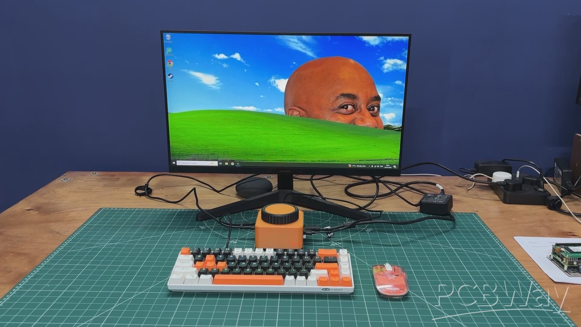
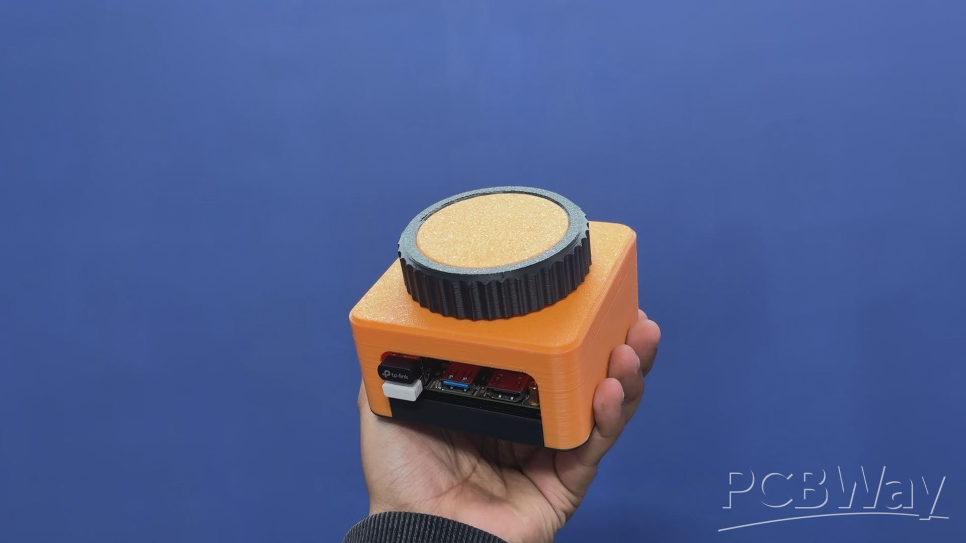
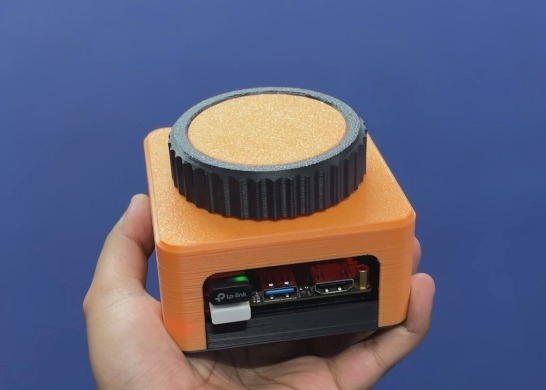
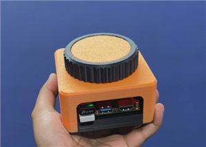
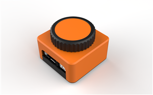
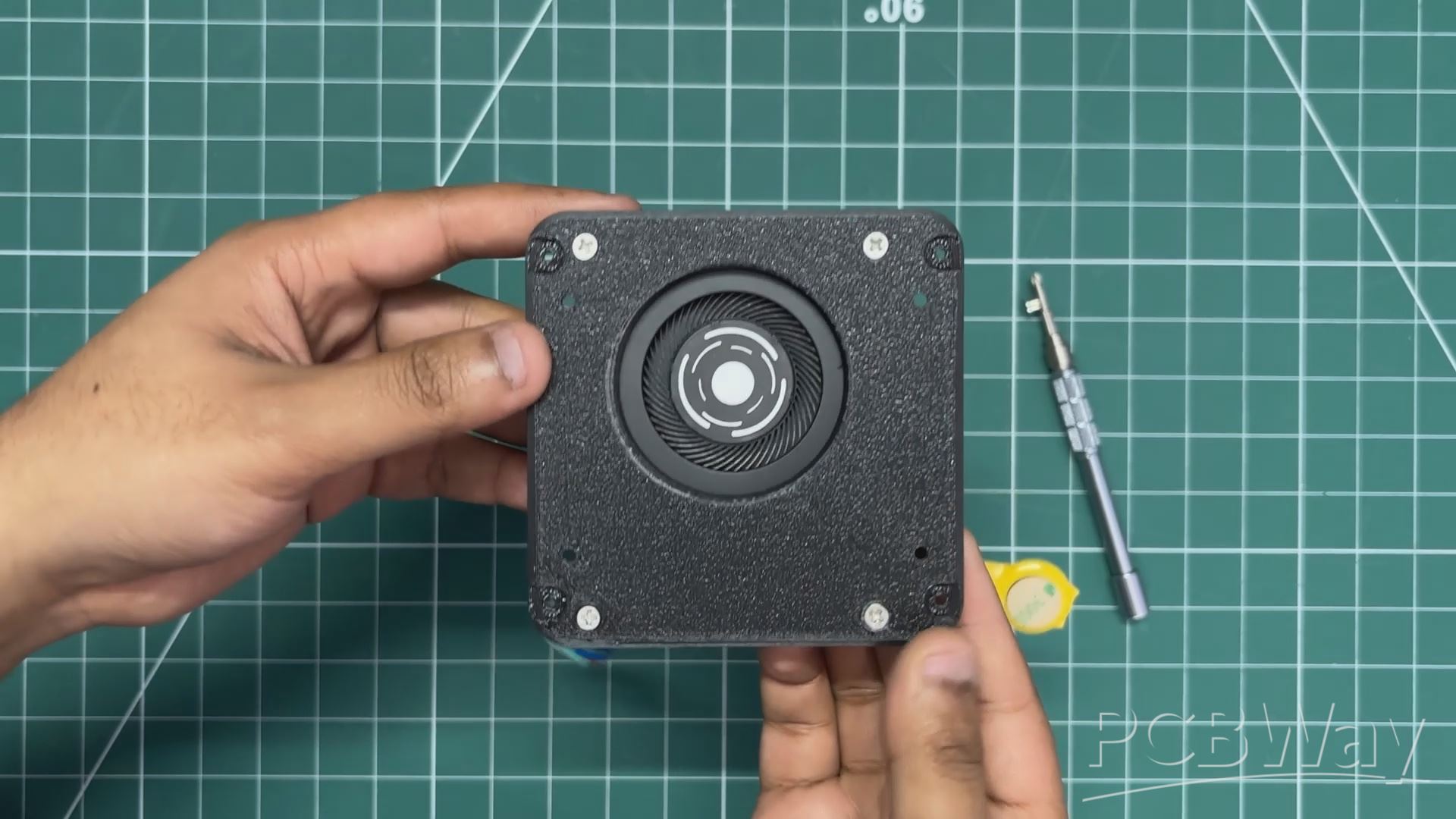
Meet IOTA STATION, a super-compact mini PC built completely from scratch, featuring a giant rotary knob used to control system volume as well as page scrolling up and down.
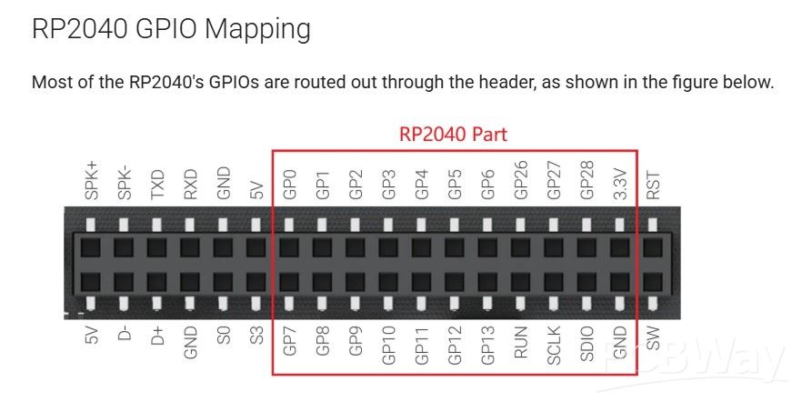
At the heart of this mini PC is the LattePanda IOTA, powered by an Intel N150 4-core processor, capable of handling far more than just basic tasks. By using the LattePanda IOTA’s onboard RP2040 co-processor, we were able to implement the HID-based volume control and scrolling encoder functionality.
The entire project was modeled in Fusion 360, then 3D printed and assembled.
This Article covers the complete build process of the project, so let’s get started with the build.
MATERIALS REQUIRED
These were the materials used in this project:
- Lattepanda IOTA Single Board Computer
- Custom PCB
- Header Pins
- Speaker 8 ohms 0.5W
- 10K Resistors
- 3D Printed Parts
- Rotary Encoder
- Jumper wires
- breadboard
HARDWARE- LATTEPANDA IOTA
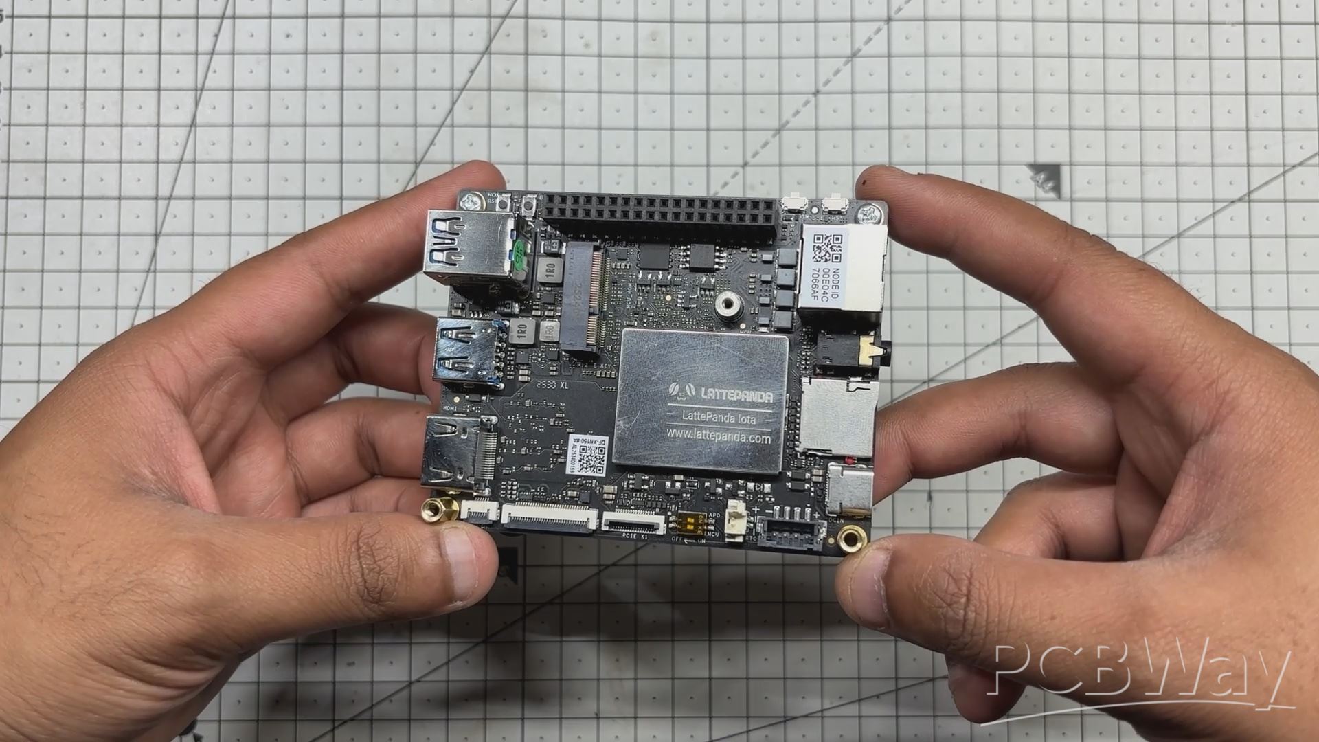
At the heart of this project is the LattePanda IOTA, a compact yet powerful x86 single-board computer designed for edge computing, embedded applications, and serious maker projects. I’m using the 16 GB RAM variant, which provides significantly more headroom than most SBCs of this size.
The LattePanda IOTA shares the same form factor as the original LattePanda V1, but thanks to its newer Intel N150 processor with 4 cores and 4 threads, it can handle much heavier workloads. I even experimented with running Bazzite on it, effectively turning it into a low-power Steam Machine.
We selected the IOTA for this project to build a super-compact mini PC capable of running Windows, making it suitable for general-purpose tasks such as web browsing.
Key Specifications (16 GB Variant)
Processor: Intel x86 CPU (energy-efficient, PC-class architecture)
Memory: 16 GB LPDDR4 RAM
Storage: Onboard eMMC (expandable via M.2 Port)
Connectivity: USB ports for peripherals, HDMI for display output, Ethernet + Wi-Fi (model dependent)
You can check out more about this board from Lattepanda's wiki page.
https://docs.lattepanda.com/content/iota_edition/get_started/
DESIGN
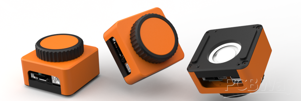
The main idea behind the design of this mini PC was simple: we wanted a giant rotary knob that actually houses the PC inside it.
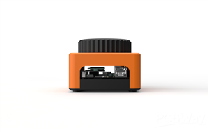
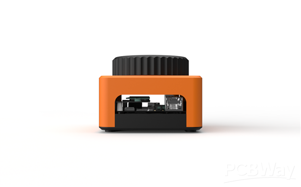
We started by creating a 3D model of the LattePanda, and around it we designed a cuboid-shaped enclosure with a large rotary knob mounted on the top. Openings were added on the left and right sides to allow easy access to the LattePanda’s I/O ports.
To ensure that all parts could be 3D printed without support material, the rotary knob mechanism was designed as a detachable assembly. This mechanism is connected to the main body using five M2 screws. The holder-like internal structure is secured to the main body from the inside, and the rotary knob is mounted on top of this holder.
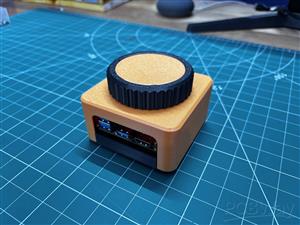
The rotary knob itself is made from two separate parts that are pressure-fitted together. Printing the knob in two different colors gives it a dual-tone black and orange finish, inspired by our mechanical keyboard, which is also used later in the demo. Inside the enclosure, the rotary encoder is positioned and held securely using a retaining bracket.
The main body is attached to the base using four M2 screws inserted from the bottom. The LattePanda itself is mounted to the base using the provided mounting holes, secured with M2.5 bolts.
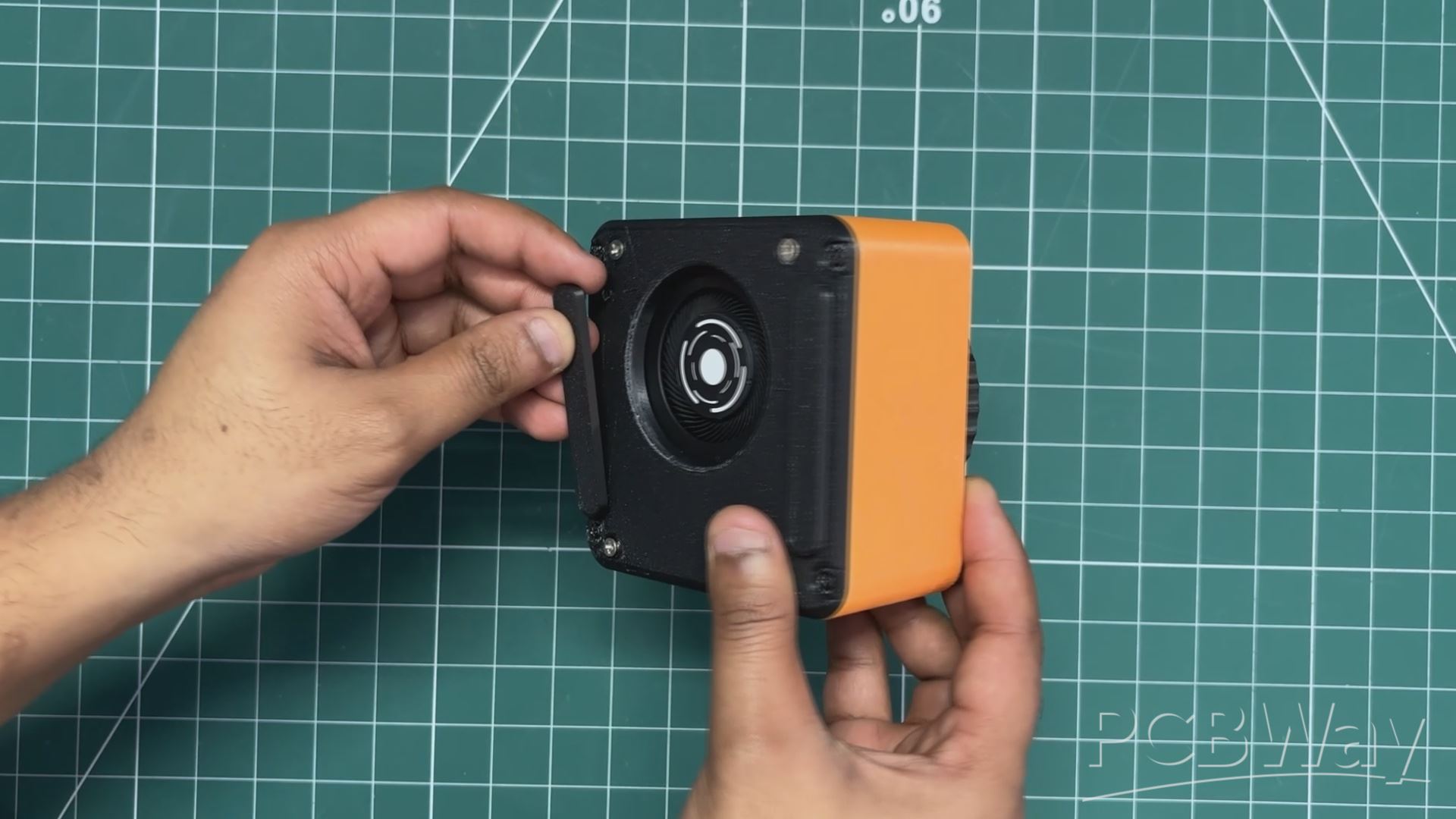
Since the base includes an opening for the LattePanda’s heatsink air intake, we also designed two small lift parts that raise the entire PC a few millimeters off the ground to improve airflow. These parts are secured using alignment pins modeled on their backside. Matching holes were added to the base, allowing the parts to be aligned and pressure-fitted into place.
3D PARTS
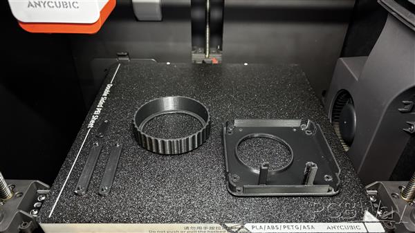
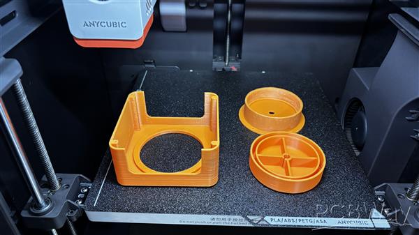
All parts were exported as mesh files before printing. We first 3D printed the outer part of the knob using black Hyper PLA, along with the base, two base resting parts, and the encoder holder. Orange Hyper PLA was used to print the encoder knob and its fixture, as well as the main body.
All components were printed with a 0.16 mm layer height and 25% infill, using my Anycubic Kobra S1 for printing all the parts.
PCB DESIGN
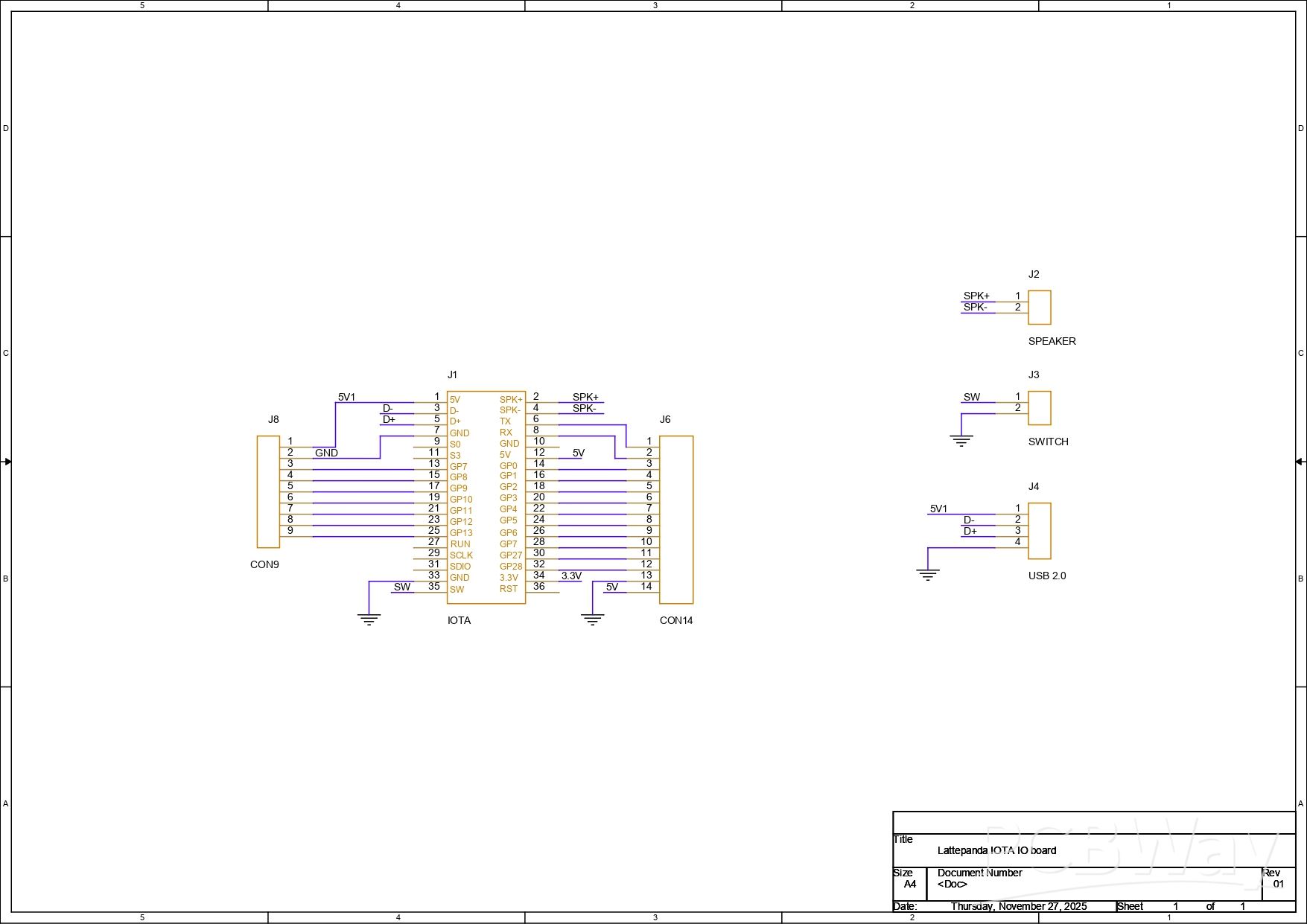
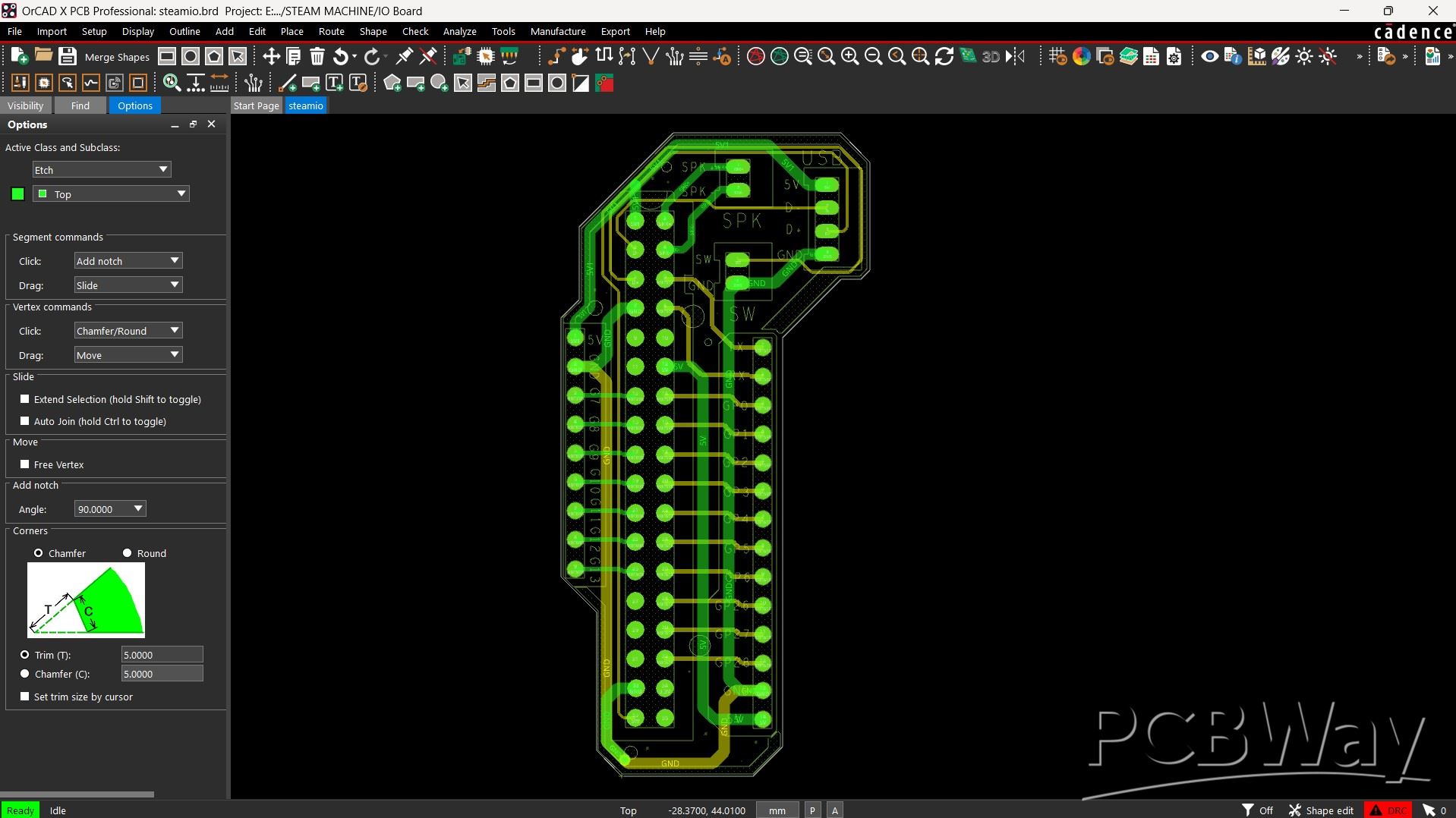
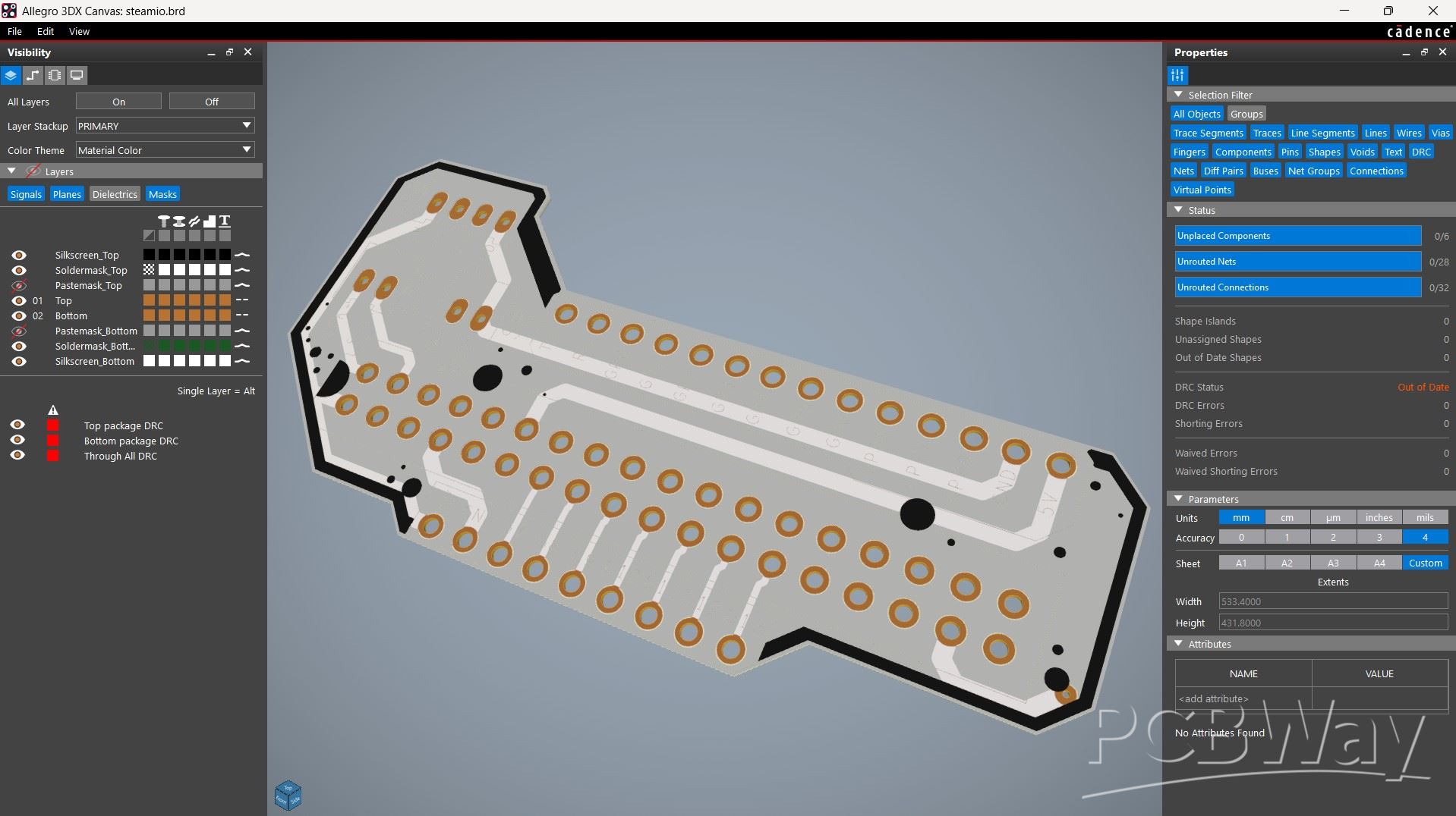
The PCB design for this project was super simple. We just needed a cleaner and more organized way to use the LattePanda’s GPIO pins for connecting the encoder and the speaker output. So the best solution was to design a breakout board that brings out all the I/O pins of the LattePanda.
We made this PCB in a way that it can also be reused in future projects, making it a handy and practical addition beyond this build.
PCBWAY SERVICE
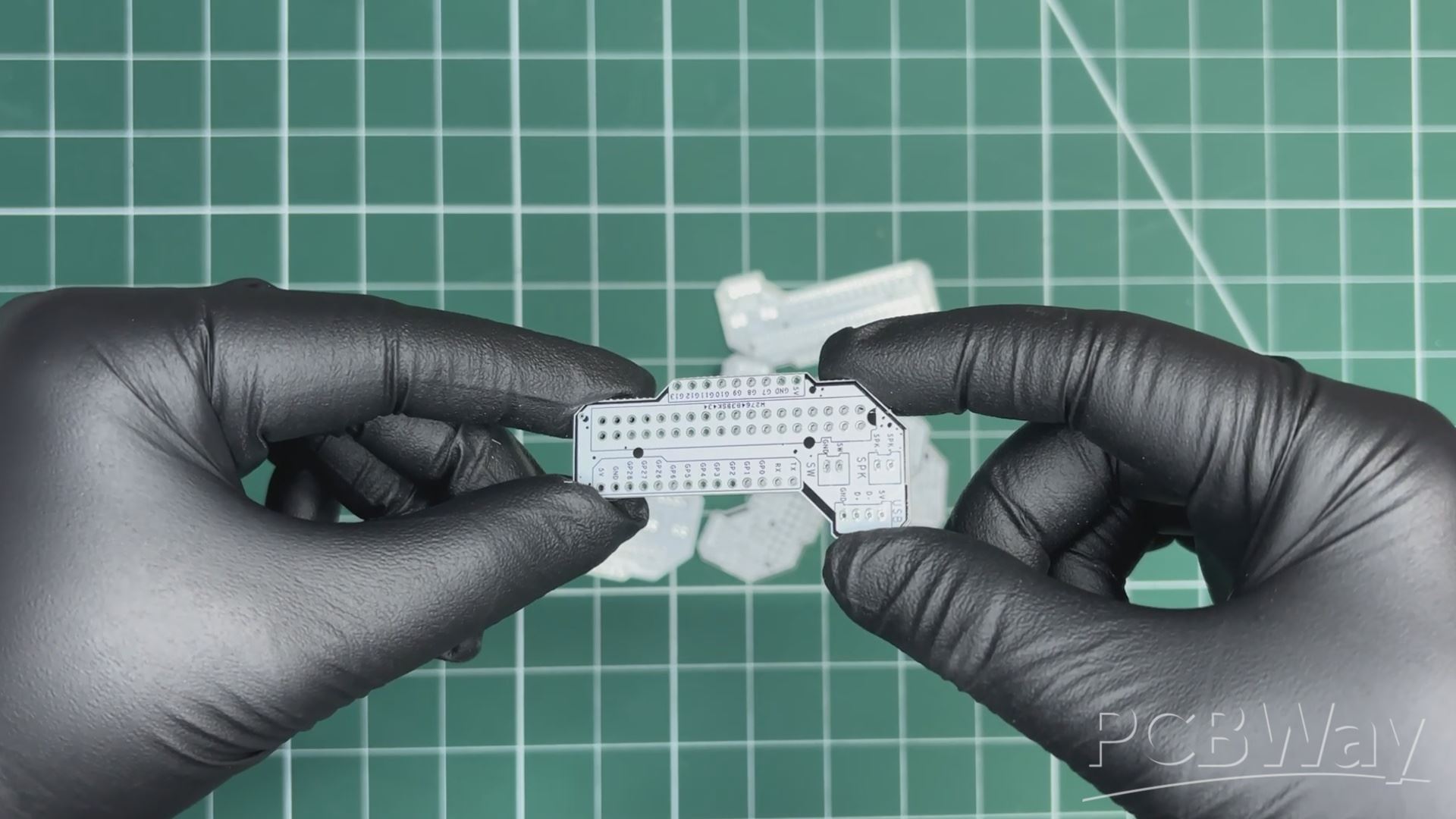
We uploaded the Gerber files to PCBWay’s quote page and placed an order for a white solder mask PCB with black silkscreen.
PCBs were received within a week, and the PCB quality was outstanding. Here, we added a few design elements on the board's silkscreen layer to increase the aesthetic appeal of the project. PCBWAY made the custom layer properly, which shows their great PCB manufacturing capabilities.
Over the past ten years, PCBWay has distinguished themselves by providing outstanding PCB manufacturing and assembly services, becoming a trusted partner for countless engineers and designers worldwide.
You guys can check out PCBWAY if you want great PCB service at an affordable rate.
PCB ASSEMBLY
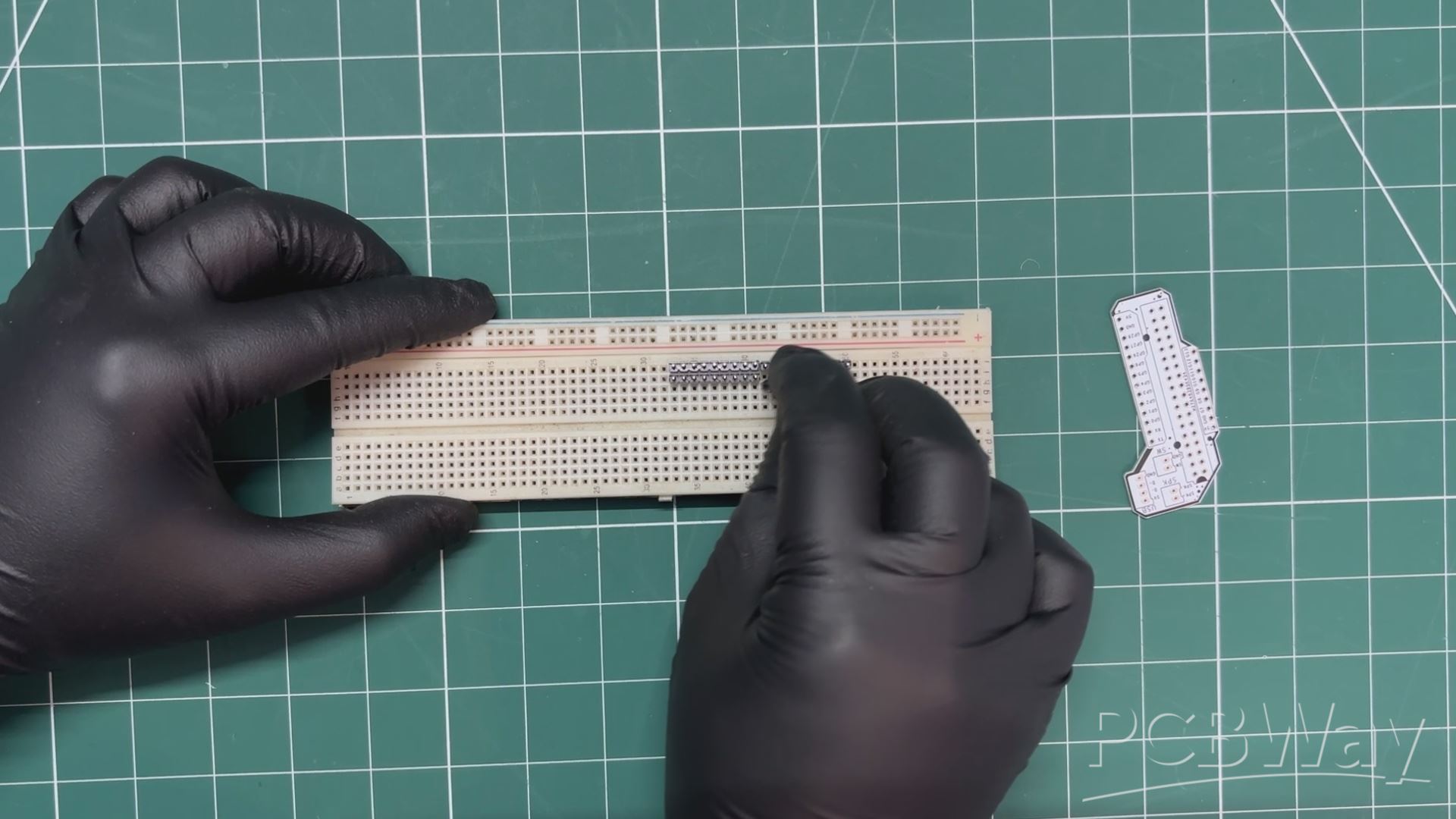
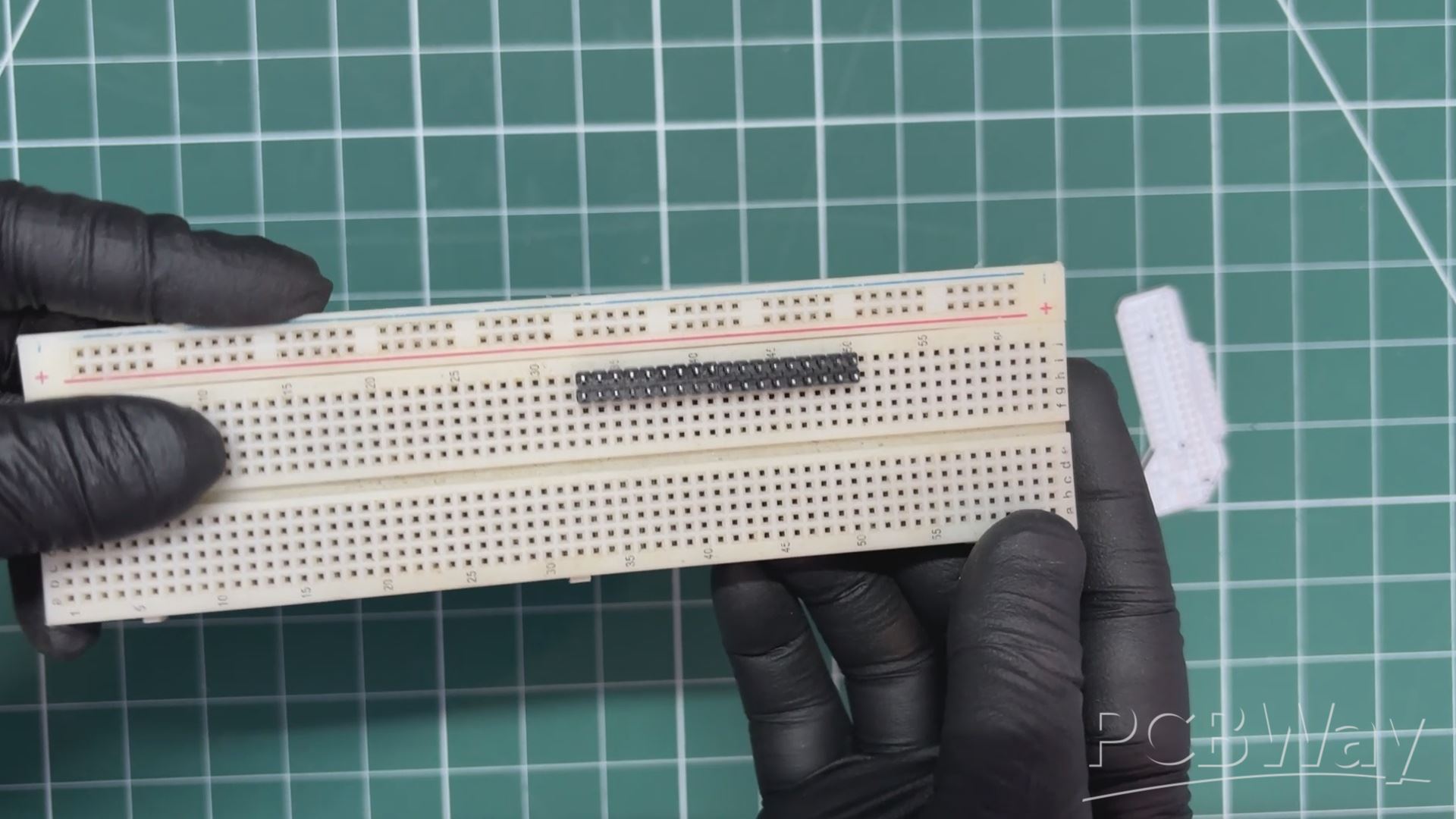
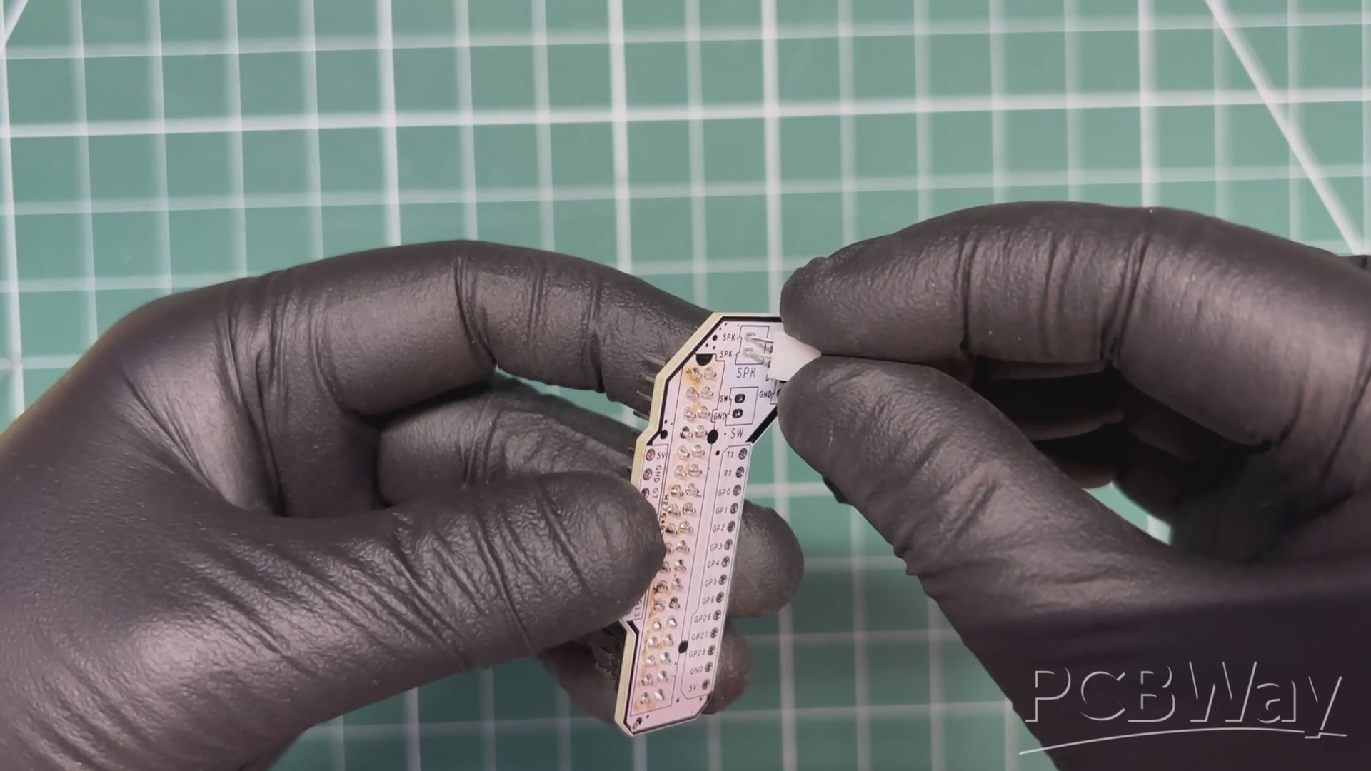
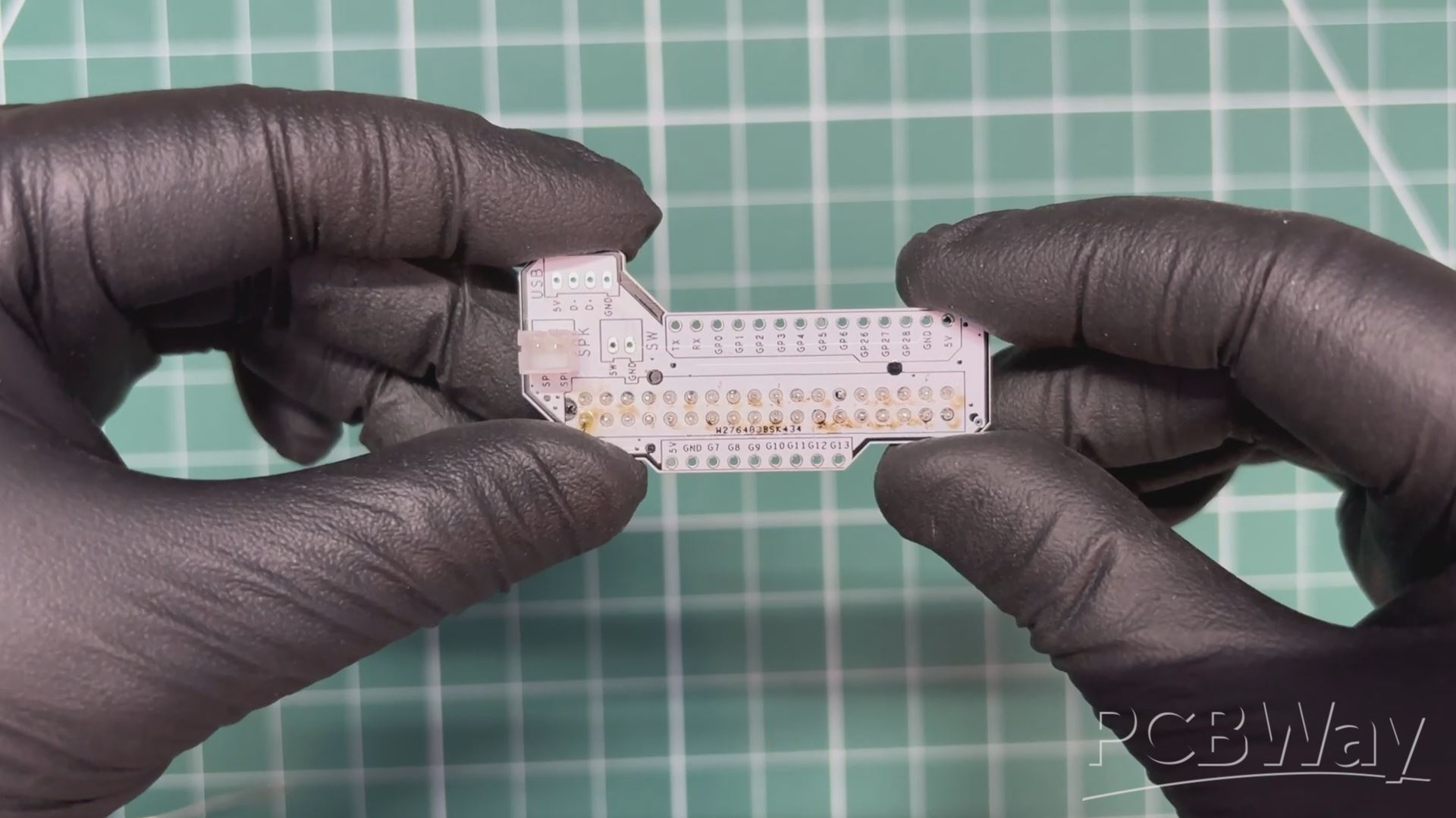
- We begin the assembly process by placing two CON18 male header pins side by side on a breadboard.
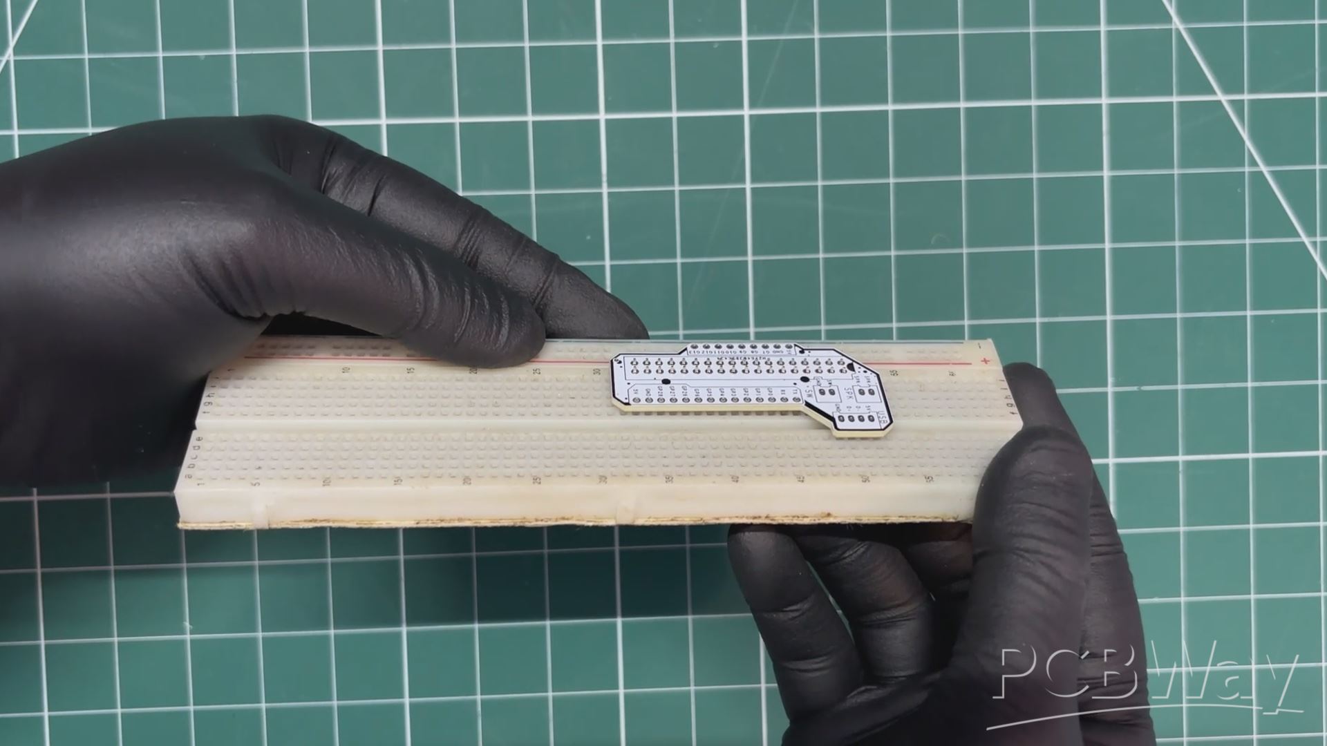
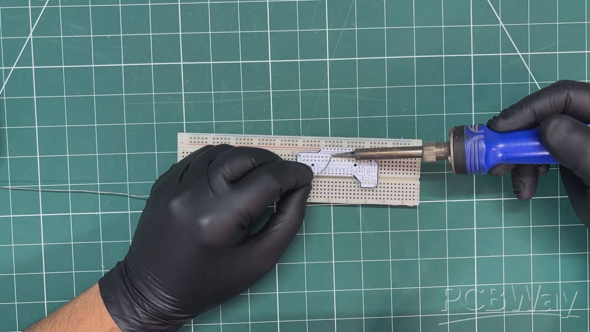
- The PCB is then placed over the header pins, and the connections are secured by soldering the leads using a soldering iron. This is a clever and reliable method for soldering breakout boards or modules, as the breadboard helps keep the header pins perfectly straight while soldering.
- Next, we place a CON2 connector onto the speaker pads on the breakout board.
- After flipping the board over, we solder the connector in place.
ENCODER WIRING
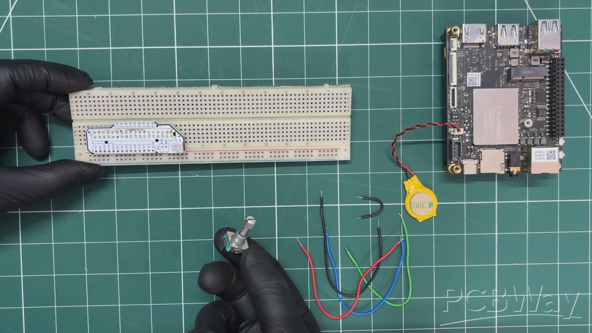
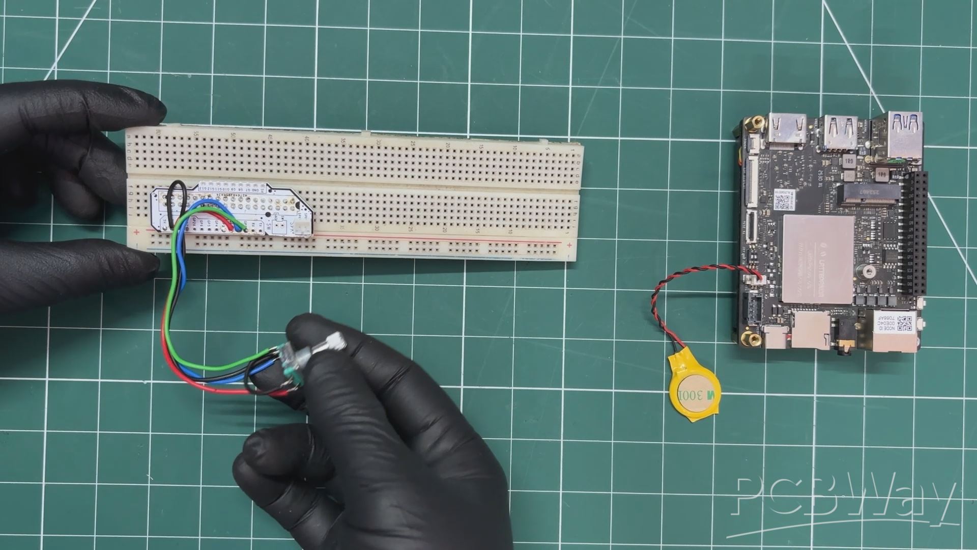
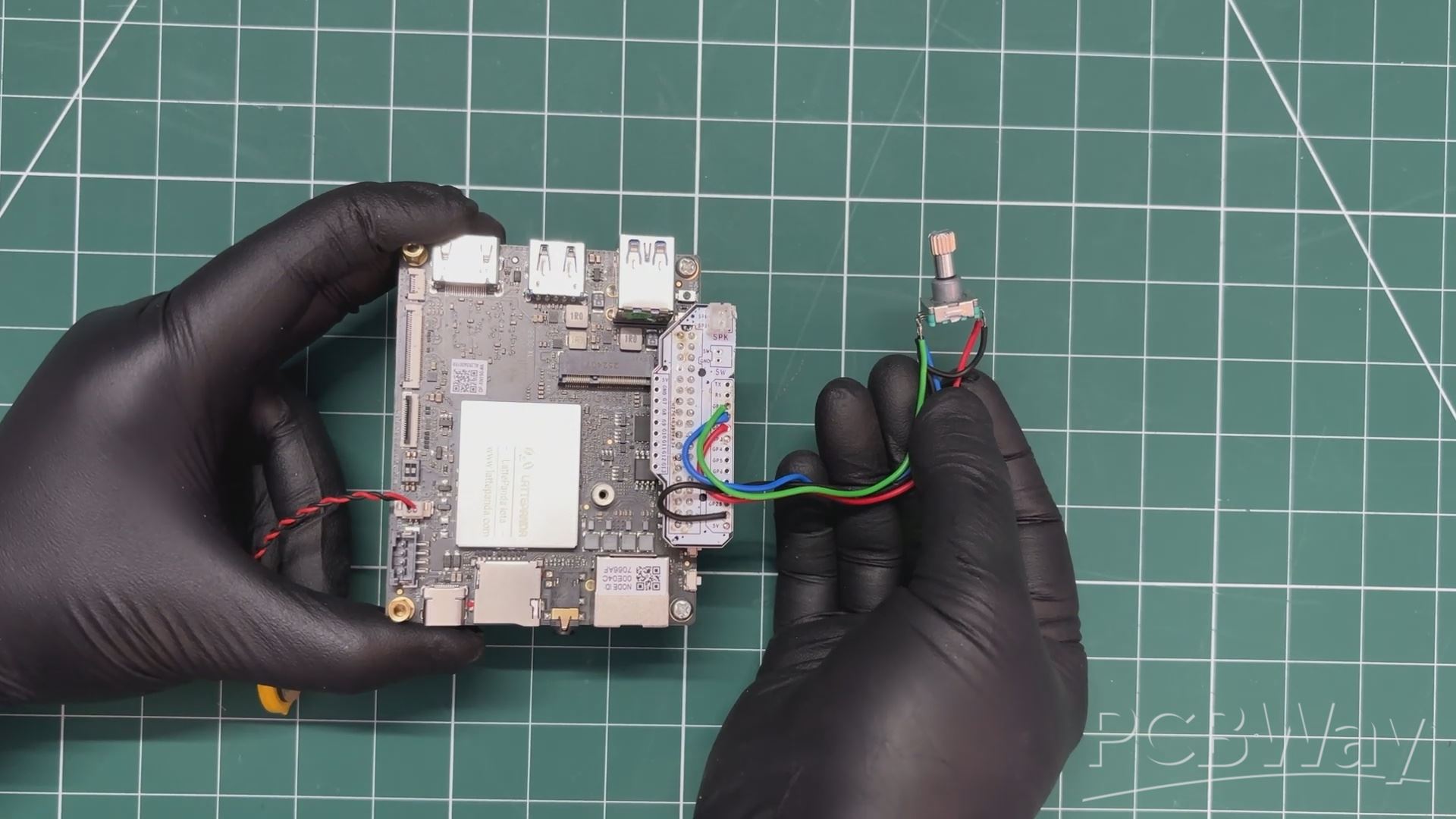
We connected GPIO 0 and GPIO 1 to the encoder’s A and B pins through 10 kΩ resistors placed in series.
The middle pin of the encoder, along with one pin of the encoder’s push button, was connected to the GND of the LattePanda.
The remaining encoder switch pin was connected to GPIO 3.
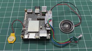
For sound output, we connected an 8-ohm, 0.5-watt round speaker to our setup using the onboard JST connector, simply plugging the speaker directly into it.
We used single-core jumper wires for all the connections, and once the wiring was complete, we moved on to the code uploading process.
MAIN CODE
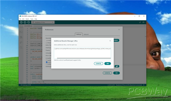
Before uploading the code, we first set up the RP2040 in the Arduino IDE. We navigated to File>Preferences and added the below JSON URL to the Additional Boards Manager URLs.
https://github.com/earlephilhower/arduino-pico/releases/download/global/package_rp2040_index.json
Next, we opened the Boards Manager, searched for Raspberry Pi Pico, and installed the board package by Earle Philhower.
After installing the Raspberry Pi Pico core for the Arduino IDE, we uploaded our main code to the onboard RP2040 co-processor.
To put the RP2040 into boot mode, we pressed and held the BOOTSEL button, then pressed and released the RST button, and finally released the BOOTSEL button. The operating system then detected the RP2040 as a new USB Mass Storage Device.
We uploaded the below code into our coprocessor.
#include <Adafruit_TinyUSB.h>
// ================== PINS ==================
#define ENC_A   0
#define ENC_B   1
#define ENC_BTN 2
// ================== HID ===================
Adafruit_USBD_HID hid_consumer;
Adafruit_USBD_HID hid_keyboard;
uint8_t const consumer_desc[] = {
TUD_HID_REPORT_DESC_CONSUMER()
};
uint8_t const keyboard_desc[] = {
TUD_HID_REPORT_DESC_KEYBOARD()
};
// ================== MODE ==================
bool volumeMode = true;
bool lastBtn = HIGH;
// ================== ENCODER (DETENT LOCK) ==================
int8_t readEncoder() {
static uint8_t last = 0b11;
static int8_t count = 0;
uint8_t now = 0;
if (digitalRead(ENC_A)) now |= 1;
if (digitalRead(ENC_B)) now |= 2;
if (now != last) {
if ((last == 0b11 && now == 0b01) ||
(last == 0b01 && now == 0b00) ||
(last == 0b00 && now == 0b10) ||
(last == 0b10 && now == 0b11))
count++;
if ((last == 0b11 && now == 0b10) ||
(last == 0b10 && now == 0b00) ||
(last == 0b00 && now == 0b01) ||
(last == 0b01 && now == 0b11))
count--;
last = now;
}
if (now == 0b11) {
if (count >= 4) { count = 0; return +1; }
if (count <= -4) { count = 0; return -1; }
count = 0;
}
return 0;
}
// ================== HID SEND ==================
void sendVolume(uint16_t key) {
hid_consumer.sendReport(0, &key, sizeof(key));
delay(2);
uint16_t zero = 0;
hid_consumer.sendReport(0, &zero, sizeof(zero));
}
void sendKey(uint8_t keycode) {
uint8_t press[8] = {0};
uint8_t release[8] = {0};
press[2] = keycode;
hid_keyboard.sendReport(0, press, sizeof(press));
delay(2);
hid_keyboard.sendReport(0, release, sizeof(release));
}
// ================== SETUP ==================
void setup() {
pinMode(ENC_A, INPUT_PULLUP);
pinMode(ENC_B, INPUT_PULLUP);
pinMode(ENC_BTN, INPUT_PULLUP);
hid_consumer.setReportDescriptor(consumer_desc, sizeof(consumer_desc));
hid_consumer.begin();
hid_keyboard.setReportDescriptor(keyboard_desc, sizeof(keyboard_desc));
hid_keyboard.begin();
while (!TinyUSBDevice.mounted()) delay(10);
}
// ================== LOOP ==================
void loop() {
// Button toggle
bool btn = digitalRead(ENC_BTN);
if (lastBtn == HIGH && btn == LOW) {
volumeMode = !volumeMode;
delay(300);
}
lastBtn = btn;
// Encoder
int8_t move = readEncoder();
if (move != 0) {
if (volumeMode) {
if (move > 0)
sendVolume(HID_USAGE_CONSUMER_VOLUME_INCREMENT);
else
sendVolume(HID_USAGE_CONSUMER_VOLUME_DECREMENT);
} else {
if (move > 0)
sendKey(HID_KEY_PAGE_DOWN);
else
sendKey(HID_KEY_PAGE_UP);
}
}
}
Before using this sketch, we installed adafruit TinyUSB library before uploading, after uploading our RP2040 coprocessor turns into a USB HID device that can function as both a media controller and a keyboard input.
The rotary encoder is read using a detent-locked quadrature decoding method, ensuring that each physical click of the encoder results in only one action. By default, the encoder controls system volume, and pressing the encoder button toggles the mode between volume control and page scrolling.
In volume mode, rotating the encoder sends USB consumer control commands to increase or decrease the system volume, while in scroll mode, it sends keyboard Page Up and Page Down key events.
BASE ASSEMBLY
- We begin the base assembly process by positioning the lattepanda over the base by aligning the mounting holes of the base with lattepanda's threaded inserts.
- We next position the 8-ohm speaker in its mounting position inside the base body.
- Next, using four M2.5 bolts, we connected lattepanda with the base body.
ROTARY KNOB MAIN PART ASSEMBLY
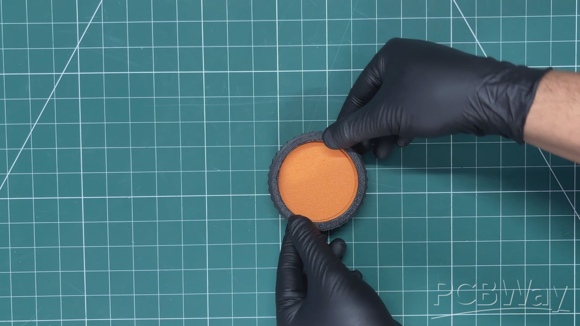
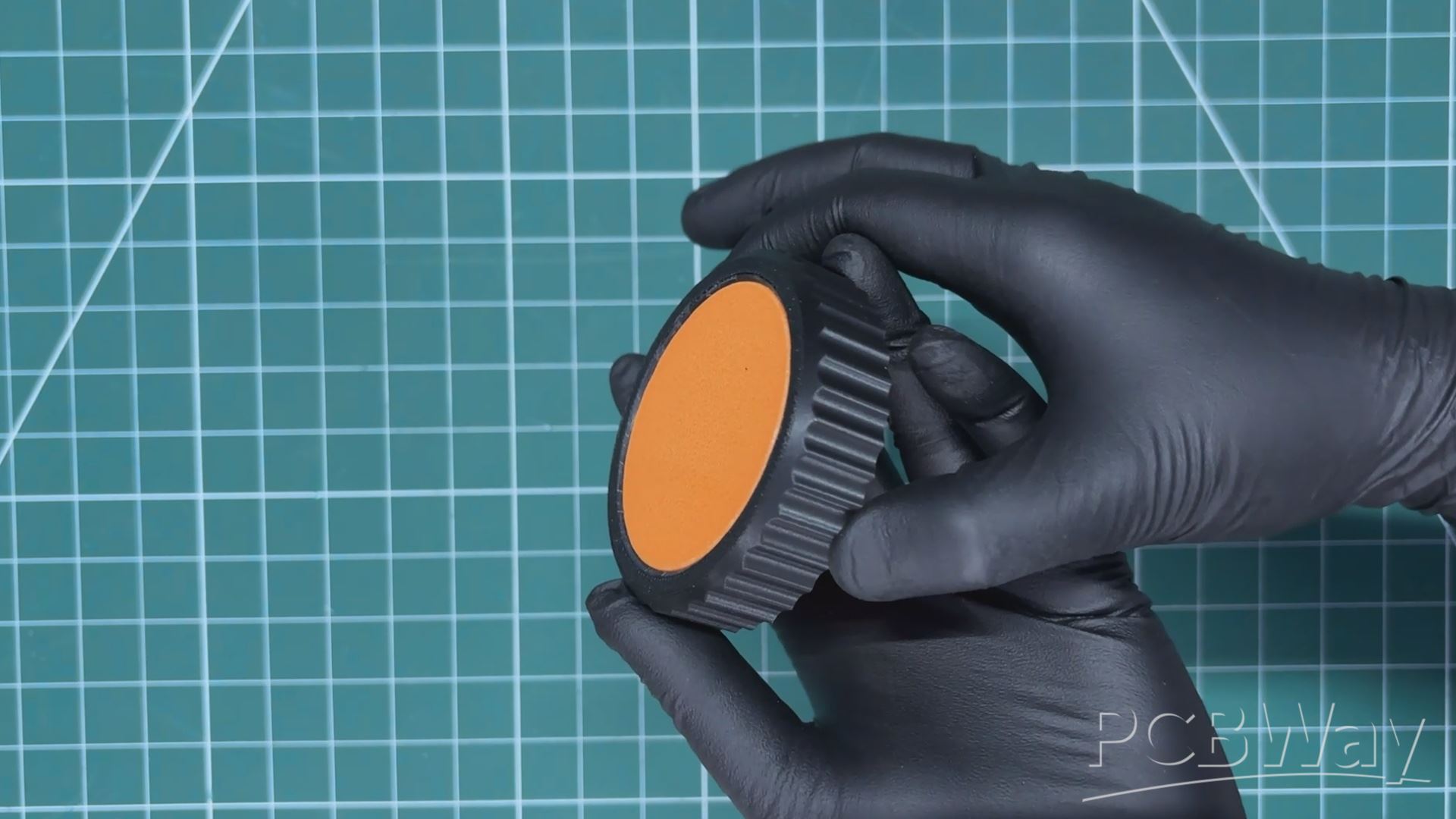
The main rotary knob consists of two parts: the main knob body and an outer grip section with grooves.
Both parts were modeled in a way that allows the outer grip, printed in black PLA, to be easily aligned over the main knob body. By pushing the grip part downward, the two pieces pressure-fit together, forming a single solid knob made from two 3D-printed components.
ROTARY KNOB ASSEMBLY
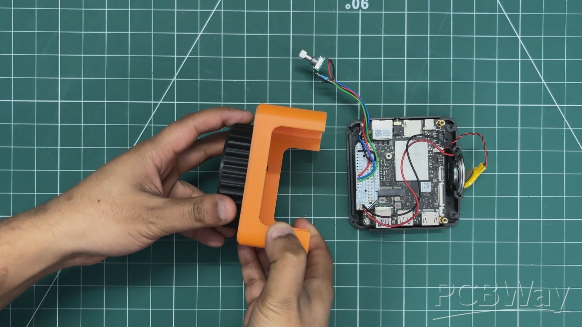
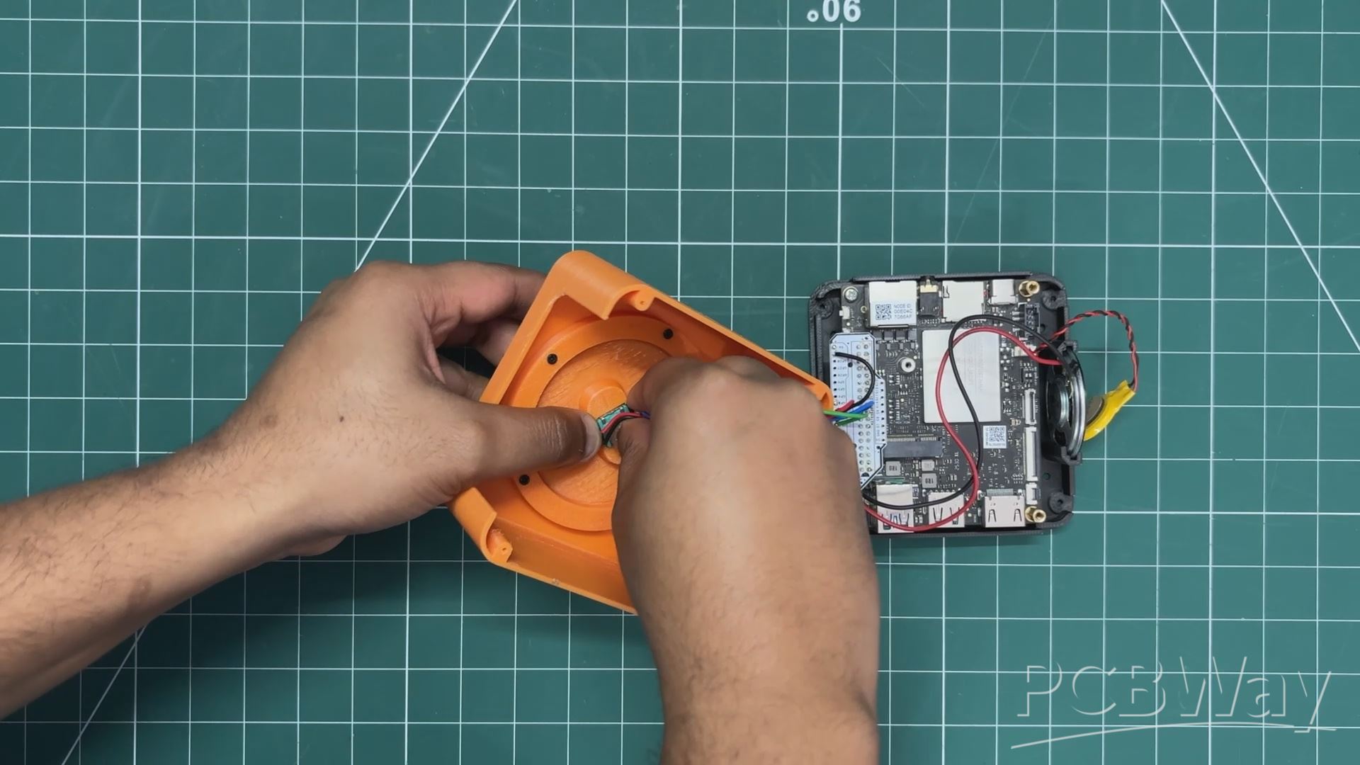
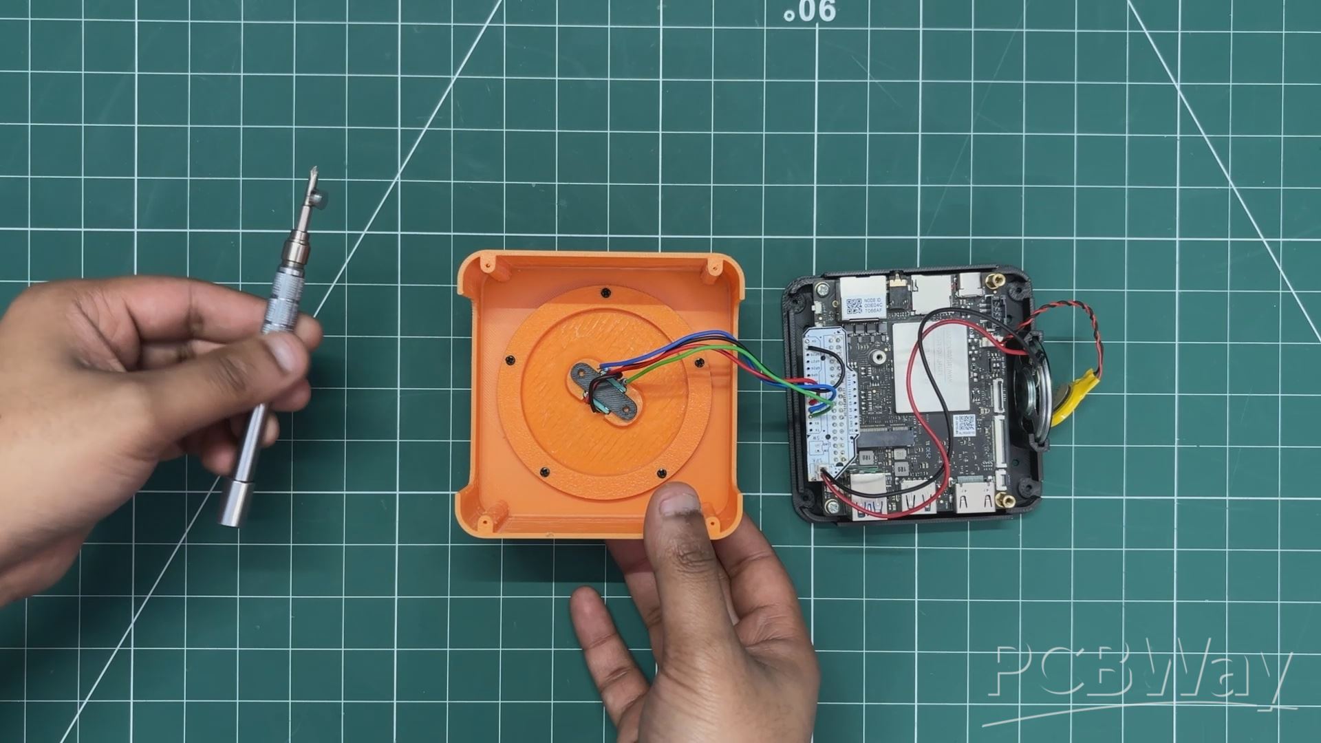
- Next, we placed the assembled rotary knob into its position on the main body, aligning it over the rotary mechanism.
- From the inside of the main body, we positioned the rotary encoder in place and applied a small amount of pressure so that it seated firmly with the main knob.
- To secure the rotary encoder, we installed the encoder holder and fixed it in place using two M2 screws.
FINAL ASSEMBLY
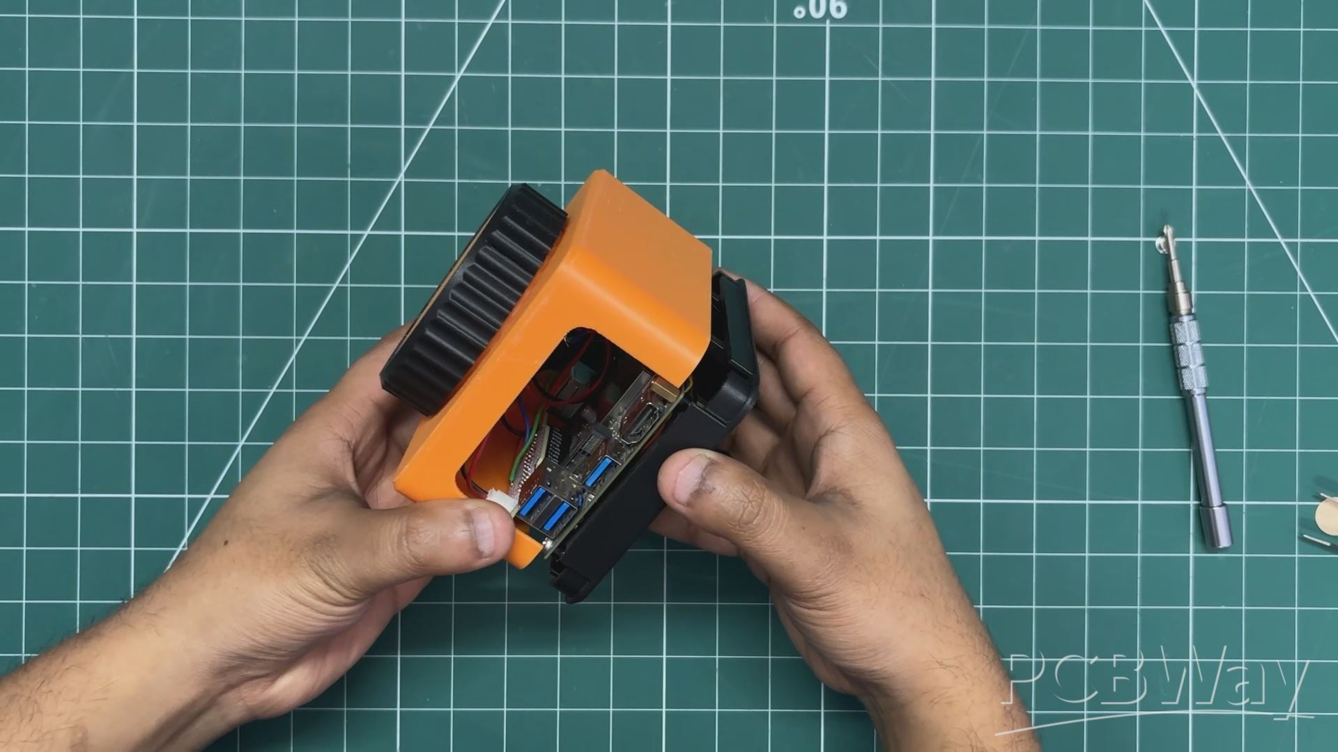
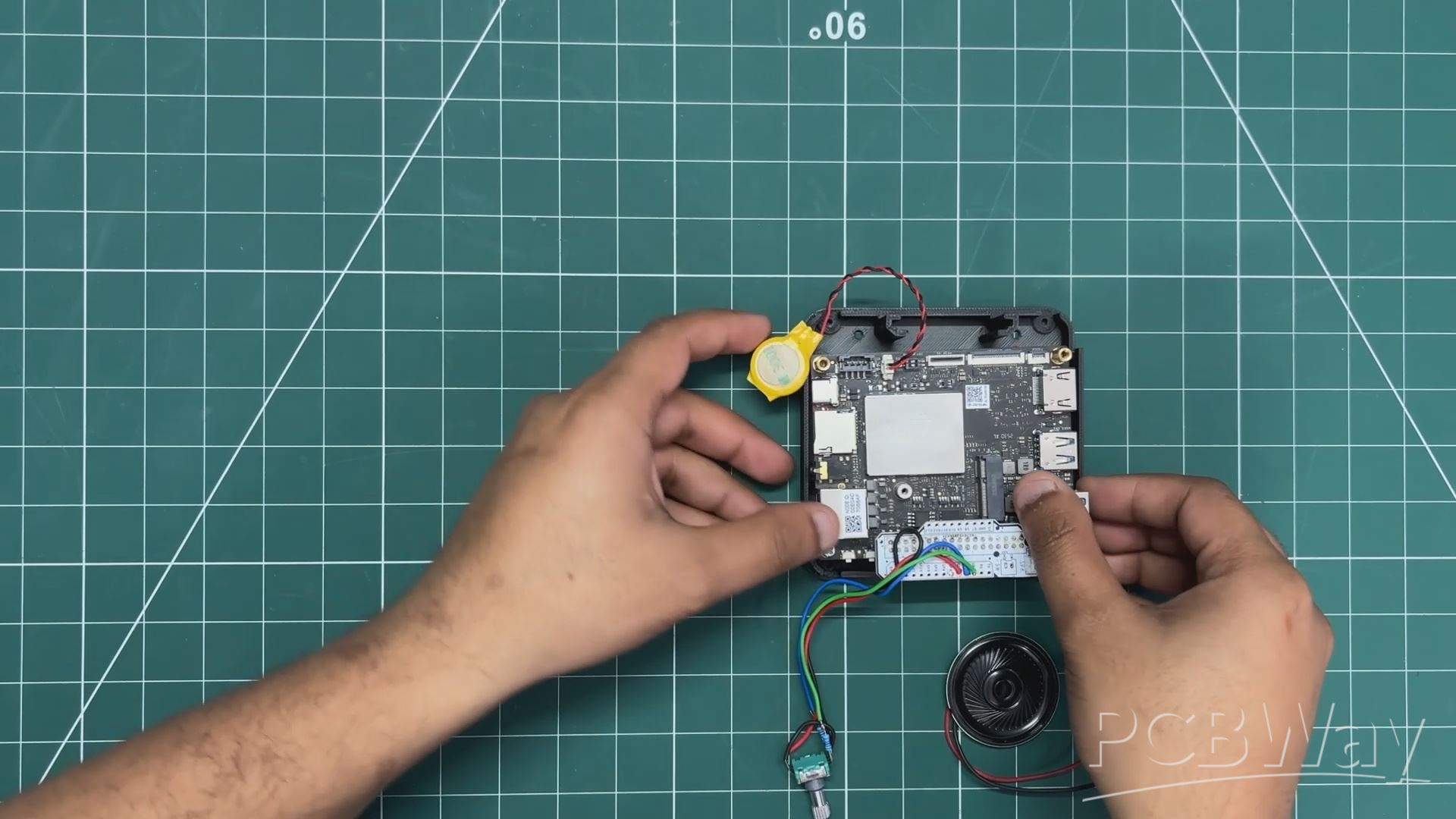
- The final assembly process begins by removing the double-sided tape from the LattePanda’s BIOS battery and attaching it to the left side inside the main body.
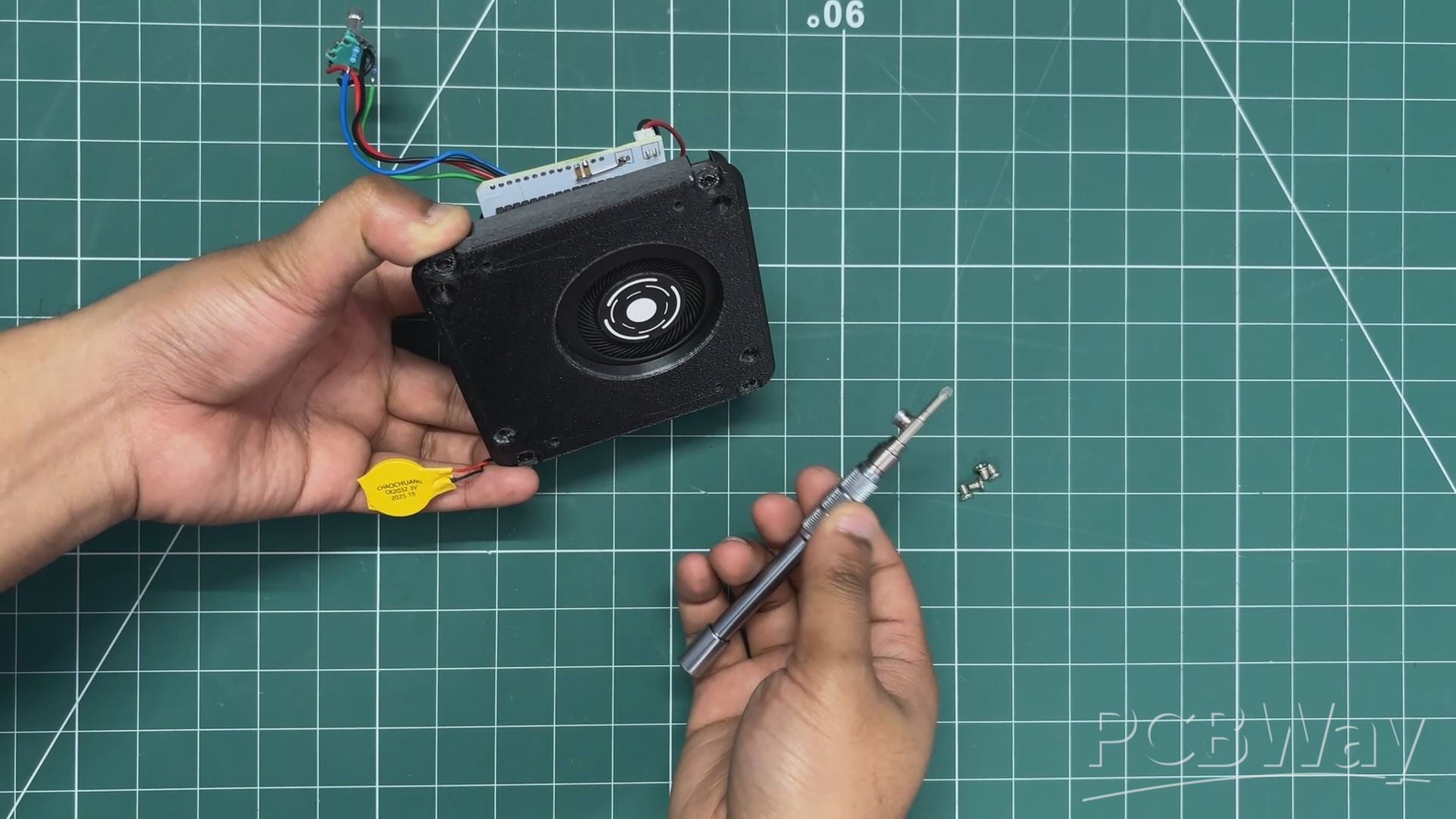
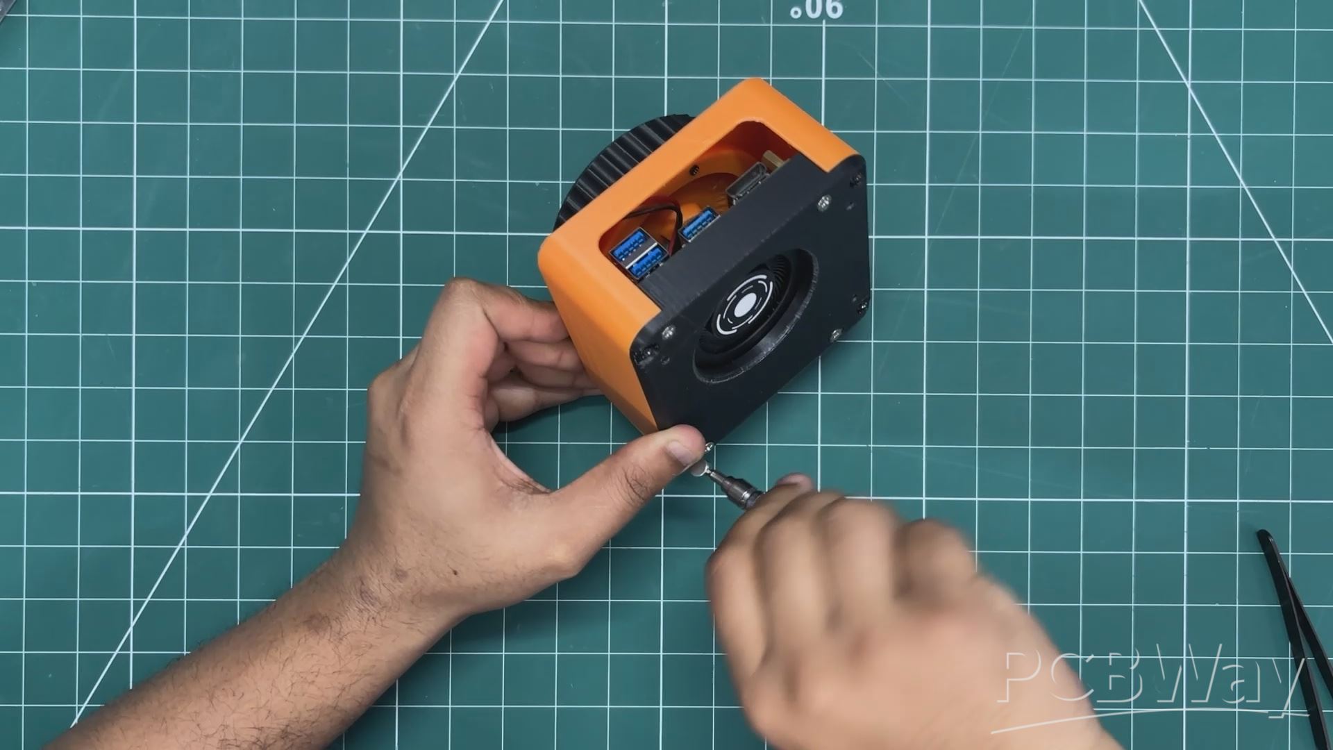
- Next, we position the main body over the base and attach the two parts together. From the bottom side, we use four M2 screws to secure them in place.
- Finally, we install the two lift parts on the bottom side. Both parts are pressure-fitted into position, and this completes the assembly process of IOTA STATION.
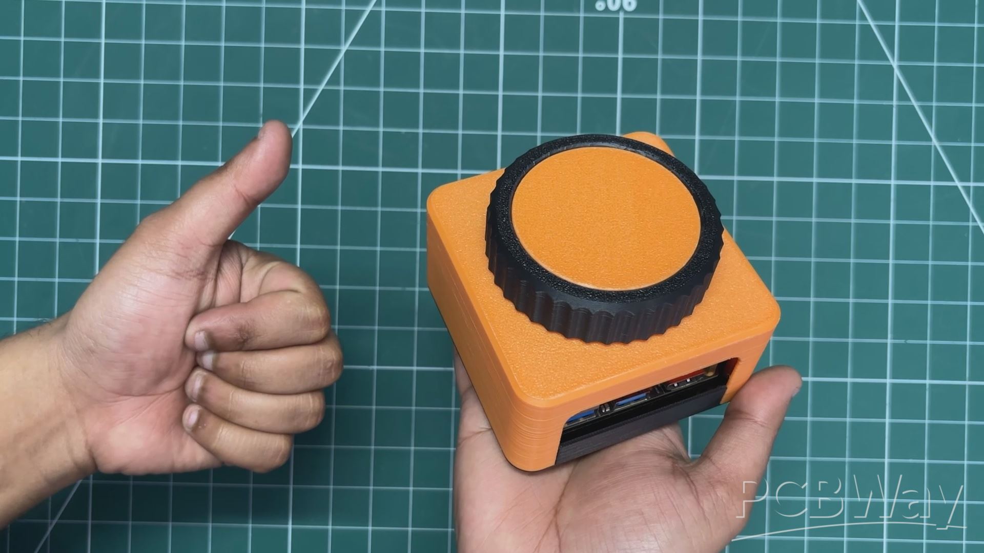
RESULT
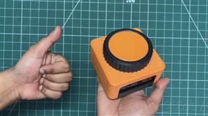
So here’s the end result of this simple build — IOTA STATION, a tiny PC with a giant rotary knob that controls system volume and page scrolling, all powered by the LattePanda IOTA.
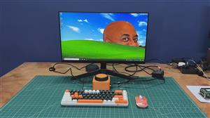
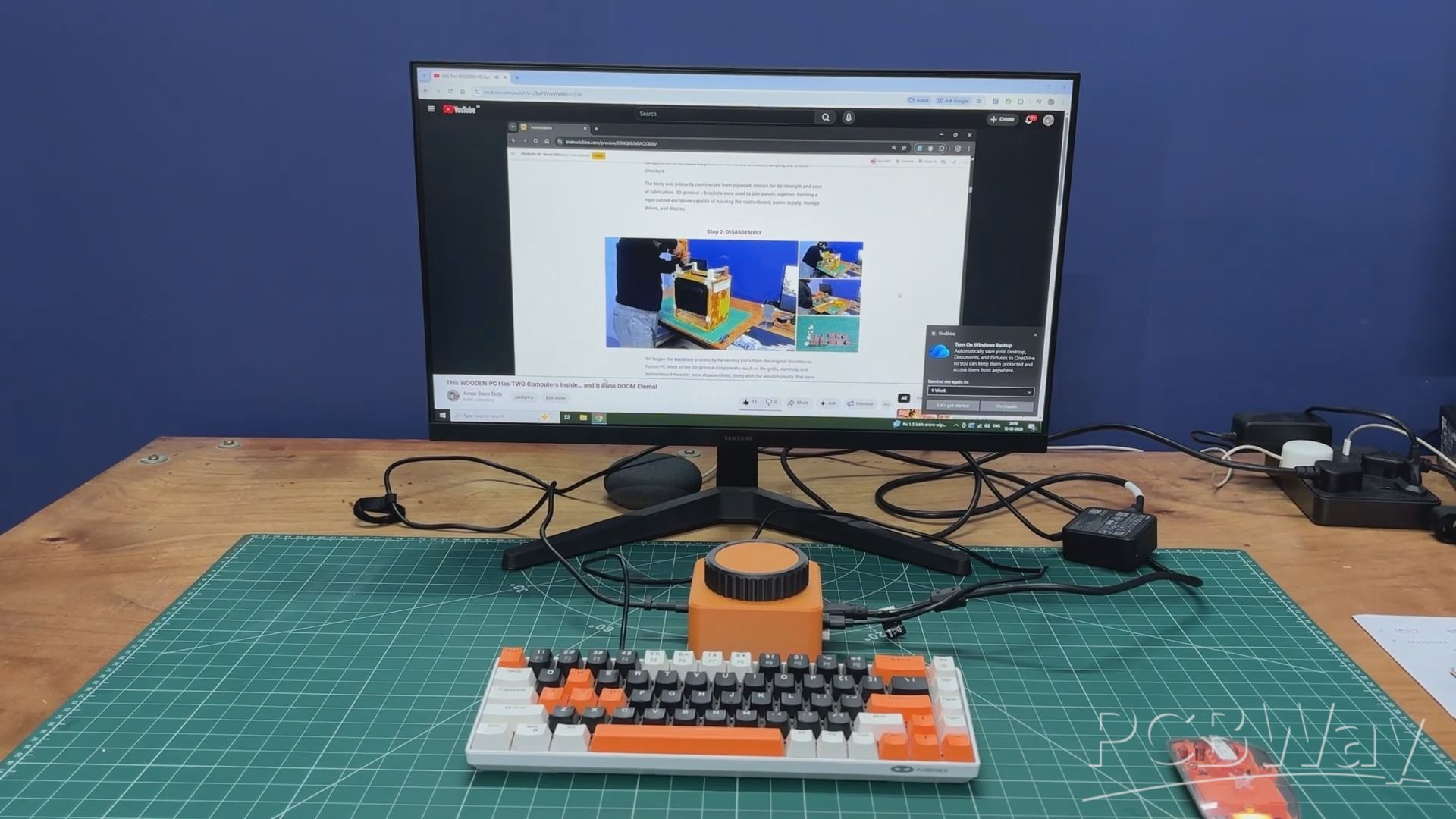
For testing, we tried scrolling through webpages and adjusting system sound, and everything worked smoothly thanks to the onboard RP2040 co-processor integrated into the LattePanda IOTA. With this knob, we can easily scroll through webpages, navigate comment sections, and control system volume with ease.
Thanks to its small form factor, this mini PC is highly portable and can be easily carried in a backpack. The LattePanda IOTA can handle most everyday tasks we throw at it, such as general web browsing, Microsoft Office work, and even some light gaming, which makes it surprisingly useful for its size.
In addition, we appreciate PCBWAY's support of this project. Visit them for a variety of PCB-related services, such as stencil and PCB assembly services, as well as 3D printing services.
All the details related to this project—including the code, 3D models, and build files—are attached in the article. If you need any assistance or have questions, feel free to drop a comment.
Thanks for sticking around till the end, and I’ll be back soon with a new project!
#include <Adafruit_TinyUSB.h>

// ================== PINS ==================
#define ENC_A   0
#define ENC_B   1
#define ENC_BTN 2

// ================== HID ===================
Adafruit_USBD_HID hid_consumer;
Adafruit_USBD_HID hid_keyboard;

uint8_t const consumer_desc[] = {
  TUD_HID_REPORT_DESC_CONSUMER()
};

uint8_t const keyboard_desc[] = {
  TUD_HID_REPORT_DESC_KEYBOARD()
};

// ================== MODE ==================
bool volumeMode = true;
bool lastBtn = HIGH;

// ================== ENCODER (DETENT LOCK) ==================
int8_t readEncoder() {
  static uint8_t last = 0b11;
  static int8_t count = 0;

  uint8_t now = 0;
  if (digitalRead(ENC_A)) now |= 1;
  if (digitalRead(ENC_B)) now |= 2;

  if (now != last) {
    if ((last == 0b11 && now == 0b01) ||
        (last == 0b01 && now == 0b00) ||
        (last == 0b00 && now == 0b10) ||
        (last == 0b10 && now == 0b11))
      count++;

    if ((last == 0b11 && now == 0b10) ||
        (last == 0b10 && now == 0b00) ||
        (last == 0b00 && now == 0b01) ||
        (last == 0b01 && now == 0b11))
      count--;

    last = now;
  }

  if (now == 0b11) {
    if (count >= 4) { count = 0; return +1; }
    if (count <= -4) { count = 0; return -1; }
    count = 0;
  }

  return 0;
}

// ================== HID SEND ==================
void sendVolume(uint16_t key) {
  hid_consumer.sendReport(0, &key, sizeof(key));
  delay(2);
  uint16_t zero = 0;
  hid_consumer.sendReport(0, &zero, sizeof(zero));
}

void sendKey(uint8_t keycode) {
  uint8_t press[8] = {0};
  uint8_t release[8] = {0};

  press[2] = keycode;

  hid_keyboard.sendReport(0, press, sizeof(press));
  delay(2);
  hid_keyboard.sendReport(0, release, sizeof(release));
}

// ================== SETUP ==================
void setup() {
  pinMode(ENC_A, INPUT_PULLUP);
  pinMode(ENC_B, INPUT_PULLUP);
  pinMode(ENC_BTN, INPUT_PULLUP);

  hid_consumer.setReportDescriptor(consumer_desc, sizeof(consumer_desc));
  hid_consumer.begin();

  hid_keyboard.setReportDescriptor(keyboard_desc, sizeof(keyboard_desc));
  hid_keyboard.begin();

  while (!TinyUSBDevice.mounted()) delay(10);
}

// ================== LOOP ==================
void loop() {
  // Button toggle
  bool btn = digitalRead(ENC_BTN);
  if (lastBtn == HIGH && btn == LOW) {
    volumeMode = !volumeMode;
    delay(300);
  }
  lastBtn = btn;

  // Encoder
  int8_t move = readEncoder();
  if (move != 0) {
    if (volumeMode) {
      if (move > 0)
        sendVolume(HID_USAGE_CONSUMER_VOLUME_INCREMENT);
      else
        sendVolume(HID_USAGE_CONSUMER_VOLUME_DECREMENT);
    } else {
      if (move > 0)
        sendKey(HID_KEY_PAGE_DOWN);
      else
        sendKey(HID_KEY_PAGE_UP);
    }
  }
}
IOTA STATION- A Mini PC with Giant Rotary Knob
*PCBWay community is a sharing platform. We are not responsible for any design issues and parameter issues (board thickness, surface finish, etc.) you choose.


Raspberry Pi 5 7 Inch Touch Screen IPS 1024x600 HD LCD HDMI-compatible Display for RPI 4B 3B+ OPI 5 AIDA64 PC Secondary Screen(Without Speaker)
BUY NOW


- Comments(0)
- Likes(0)
More by Arnov Arnov sharma
-
 DIY XBOX Controller
Greetings everyone, and welcome back. Here's something fun and custom.This is my version of an Xbox ...
DIY XBOX Controller
Greetings everyone, and welcome back. Here's something fun and custom.This is my version of an Xbox ...
-
 Pocket SNES
Greetings everyone, and welcome back! Today, I’ve got something fun and tiny to share—the Pocket SNE...
Pocket SNES
Greetings everyone, and welcome back! Today, I’ve got something fun and tiny to share—the Pocket SNE...
-
 Batocera Arcade Box
Greetings everyone and welcome back, Here's something. Fun and nostalgic. Right now, we are using ou...
Batocera Arcade Box
Greetings everyone and welcome back, Here's something. Fun and nostalgic. Right now, we are using ou...
-
 64x32 Matrix Panel Setup with PICO 2
Greetings everyone and welcome back.So here's something fun and useful: a Raspberry Pi Pico 2-powere...
64x32 Matrix Panel Setup with PICO 2
Greetings everyone and welcome back.So here's something fun and useful: a Raspberry Pi Pico 2-powere...
-
 Portable Air Quality Meter
Hello everyone, and welcome back! Today, I have something incredibly useful for you—a Portable Air Q...
Portable Air Quality Meter
Hello everyone, and welcome back! Today, I have something incredibly useful for you—a Portable Air Q...
-
 WALKPi PCB Version
Greetings everyone and welcome back, This is the WalkPi, a homebrew audio player that plays music fr...
WALKPi PCB Version
Greetings everyone and welcome back, This is the WalkPi, a homebrew audio player that plays music fr...
-
 Delete Button XL
Greetings everyone and welcome back, and here's something fun and useful.In essence, the Delete Butt...
Delete Button XL
Greetings everyone and welcome back, and here's something fun and useful.In essence, the Delete Butt...
-
 Arduino Retro Game Controller
Greetings everyone and welcome back. Here's something fun.The Arduino Retro Game Controller was buil...
Arduino Retro Game Controller
Greetings everyone and welcome back. Here's something fun.The Arduino Retro Game Controller was buil...
-
 Super Power Buck Converter
Greetings everyone and welcome back!Here's something powerful, The SUPER POWER BUCK CONVERTER BOARD ...
Super Power Buck Converter
Greetings everyone and welcome back!Here's something powerful, The SUPER POWER BUCK CONVERTER BOARD ...
-
 Pocket Temp Meter
Greetings and welcome back.So here's something portable and useful: the Pocket TEMP Meter project.As...
Pocket Temp Meter
Greetings and welcome back.So here's something portable and useful: the Pocket TEMP Meter project.As...
-
 Pico Powered DC Fan Driver
Hello everyone and welcome back.So here's something cool: a 5V to 12V DC motor driver based around a...
Pico Powered DC Fan Driver
Hello everyone and welcome back.So here's something cool: a 5V to 12V DC motor driver based around a...
-
 Mini Solar Light Project with a Twist
Greetings.This is the Cube Light, a Small and compact cube-shaped emergency solar light that boasts ...
Mini Solar Light Project with a Twist
Greetings.This is the Cube Light, a Small and compact cube-shaped emergency solar light that boasts ...
-
 PALPi V5 Handheld Retro Game Console
Hey, Guys what's up?So this is PALPi which is a Raspberry Pi Zero W Based Handheld Retro Game Consol...
PALPi V5 Handheld Retro Game Console
Hey, Guys what's up?So this is PALPi which is a Raspberry Pi Zero W Based Handheld Retro Game Consol...
-
 DIY Thermometer with TTGO T Display and DS18B20
Greetings.So this is the DIY Thermometer made entirely from scratch using a TTGO T display board and...
DIY Thermometer with TTGO T Display and DS18B20
Greetings.So this is the DIY Thermometer made entirely from scratch using a TTGO T display board and...
-
 Motion Trigger Circuit with and without Microcontroller
GreetingsHere's a tutorial on how to use an HC-SR505 PIR Module with and without a microcontroller t...
Motion Trigger Circuit with and without Microcontroller
GreetingsHere's a tutorial on how to use an HC-SR505 PIR Module with and without a microcontroller t...
-
 Motor Driver Board Atmega328PU and HC01
Hey, what's up folks here's something super cool and useful if you're making a basic Robot Setup, A ...
Motor Driver Board Atmega328PU and HC01
Hey, what's up folks here's something super cool and useful if you're making a basic Robot Setup, A ...
-
 Power Block
Hey Everyone what's up!So this is Power block, a DIY UPS that can be used to power a bunch of 5V Ope...
Power Block
Hey Everyone what's up!So this is Power block, a DIY UPS that can be used to power a bunch of 5V Ope...
-
 Goku PCB Badge V2
Hey everyone what's up!So here's something SUPER cool, A PCB Board themed after Goku from Dragon Bal...
Goku PCB Badge V2
Hey everyone what's up!So here's something SUPER cool, A PCB Board themed after Goku from Dragon Bal...
-
Programmable Mist Maker - XIAO / QT PY Extension
865 1 0 -
RadioHAT - Raspberry Pi radio development platform
692 0 2 -
-
-
-
-
ARPS-2 – Arduino-Compatible Robot Project Shield for Arduino UNO
3164 0 6 -
A Compact Charging Breakout Board For Waveshare ESP32-C3
3779 3 8 -
AI-driven LoRa & LLM-enabled Kiosk & Food Delivery System
4120 2 2


