From thermal bottleneck to first PCB: designing a Beelink S13 fan controller with AI as a tool - and keeping authorship human
This project didn’t start as a PCB—it started as a thermal problem.
A Beelink S13 mini PC was hitting its limits inside a constrained enclosure, pushing me to rethink airflow and active cooling.
What began as a simple fan mod evolved into a custom ESP32‑S3 fan controller PCB to reliably manage power, control, and integration.
Along the way, I used AI as a design partner—but kept all architectural decisions, trade-offs, and accountability firmly human.
The result is a beginner-friendly, modular, and robust design that prioritizes clarity and reliability over complexity.
This project is both a practical solution and a case study in modern engineering: AI accelerates the process—but humans remain responsible for the outcome.
-#-#-#-#-#-#-#-#-#-#-#-#-#-#-#-
Some of you may have realized that this initial text was generated by AI. While this is all nice - there is already enough mediocre AI sludge in the net. So while I use AI to support my work. I take full accountability for the result because my goal from the start was to keep authorship in my hands - I can and will explain my decisions. And most likely I will do mistakes :)
Right now I am not 100% sure if AI saved me more time or cost me more time to troubleshoot and hunt for errors and wrong LCSC Part numbers the AI found. Like a part promised to be an capacitor and ended up as a 2x3 Header .-)
But this is also for me to learn what AI can do and what not. And I want to share with you as well
-#-#-#-#-#-#-#-#-#-#-#-#-#-#-#-
Still evolving - to be updated
Here a sneak preview what I plan to post:
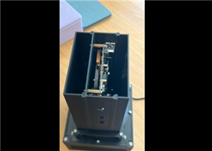
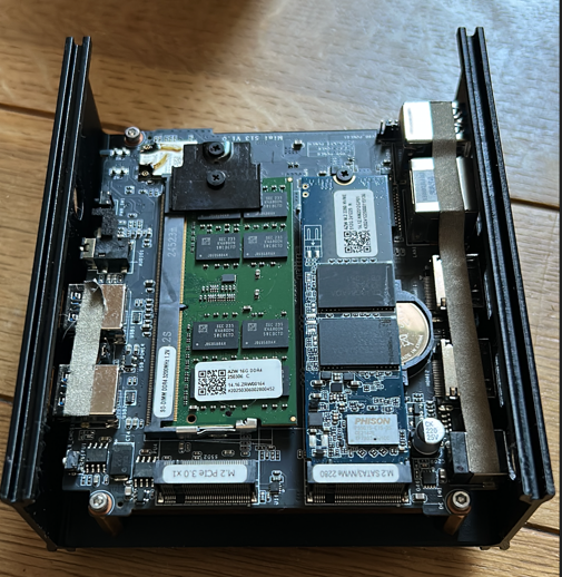
The beelink S13 was unleashed in cw 19
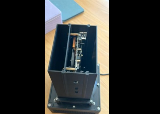
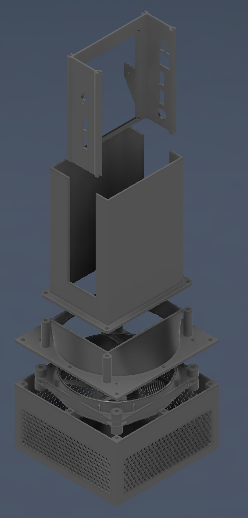
First by a custom designed case with a sled to also be able to house other miniboards
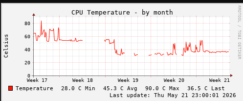
Running the 12V Fan on an adjustable desktop PSU on round about 5V
The S13 in its custom housing
Upgrading to a POC circuit to control the fan with live data from the S13
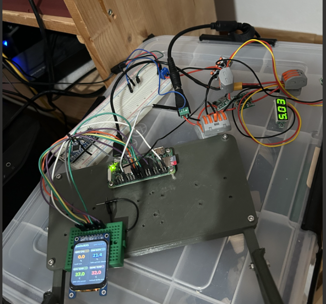
2 Power domains (stepdown bucks) 12V for the fan and 5V for the PI Zero 2W feed by a 24Volt power brick through a barrel jack
On the breadboard an open collector setup to pull down the fan PWM and a St7789 Display with live telemetry from the S13

The PI receiving the telemetry from the S13 running linux via API and adjusting the fan pwm through a hysteresis
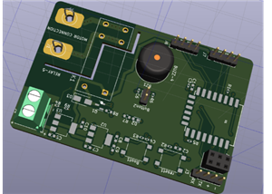
Now I am on the way to take this "mess" into a PCB:
- Full power protection - I trashed 2 fans already because of over voltage
- reverse polarity protection - I bet you achieved a reverse hookup on those screw terminals ;)
- Moveing to a leaner ESP32-S3 instead of the PI
- 4 pin Headers for the fan - inclusive 12V power rail
- dedicated buck for the 3.3V of the ESP32 and the display
- solid programmability with an USB to UART bridge
- 8 Pin Headers with all the SPI and pins connected to the ESP32 to drive a ST7789 display
I would say round about 75% of the schematics is done and should be pretty solid (I hope )
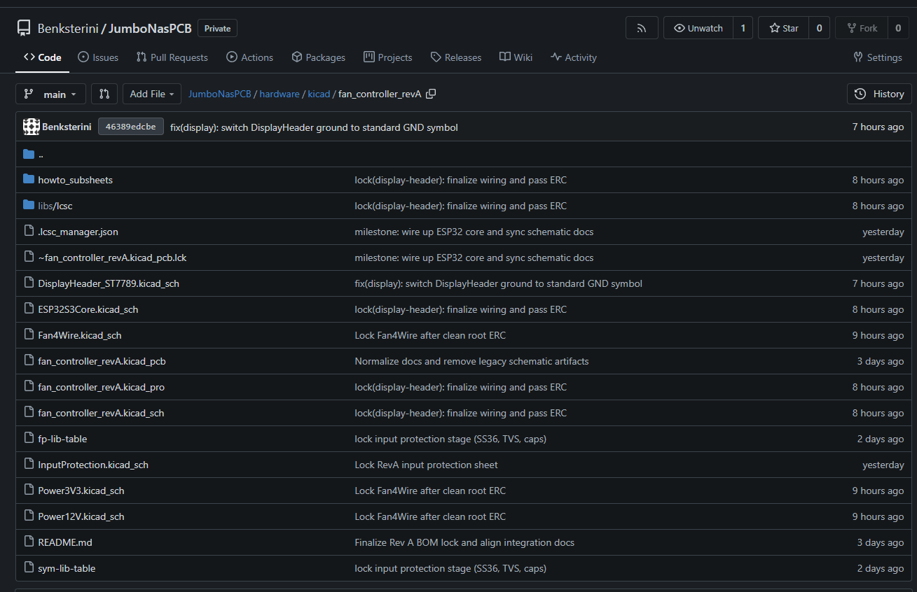
Stay tuned if interested - I plan to finsish the PCB design the next 2 weeks
From thermal bottleneck to first PCB: designing a Beelink S13 fan controller with AI as a tool - and keeping authorship human








Raspberry Pi 5 7 Inch Touch Screen IPS 1024x600 HD LCD HDMI-compatible Display for RPI 4B 3B+ OPI 5 AIDA64 PC Secondary Screen(Without Speaker)
BUY NOW


- Comments(2)
- Likes(0)
More by Janster Benksterini
-
-
ARPS-2 – Arduino-Compatible Robot Project Shield for Arduino UNO
2387 0 5 -
A Compact Charging Breakout Board For Waveshare ESP32-C3
2863 3 7 -
AI-driven LoRa & LLM-enabled Kiosk & Food Delivery System
3073 2 1 -
-
-
-
ESP32-C3 BLE Keyboard - Battery Powered with USB-C Charging
3121 0 2 -