


|
arduino IDEArduino
|
|

|
PrusaslicerPrusa
|
|

|
FreeCad |
|
|
|
EasyEDAEasyEDA
|
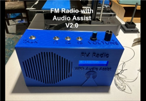
FM Radio with Audio Assist for the Visually Impaired
Introduction:
This project is the next part of a multi-year project to build a radio with audio assist prompts for the visually impaired. I'm making it open source in the hope that other makers will make them or their own modified version for the members of their own community that might need them.
Version 1.0 of this project used the Arduino talkie library to accomplish this, it is functional but the audio quality of the talkie library is poor and the vocabulary is limited. You can find the write up on the V1.0 project here: FM Radio With Audio Assist for the Visually Impaired (Version 1.0) : 10 Steps (with Pictures) - Instructables
In this project we will use a dedicated SYN6988 text to speech module for much better audio quality and an unlimited vocabulary. The project also contains some other improvements such as extended battery life, an earphone jack, a loudspeaker mute button, audio instructions on how to use the radio programmed into the program memory etc.
Radio Features:
The Radio has the following features:
FM Radio tunable from 88.0 to 108MHz in 100KHz steps.
Audible notification of:
Power on and welcome message.
Frequency.
Pre-set setting activated or preset selected along with frequency selected.
Battery Low.
Battery Charged.
USB-C Connected or disconnected.
Radio Status - Battery voltage level and USB-C Status.
Radio instructions.
Easter Eggs.
Audible beeps with each turn of the rotary encoder (100KHz steps) high tone for up, low tone for down.
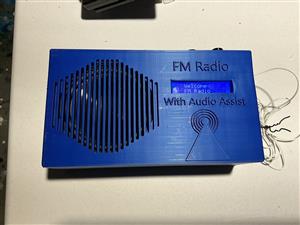
LCD Display for anyone assisting with the radio's use:
Displays Frequency.
Displays Relative Signal level
Displays Battery level momentarily on power up.
Displays Logic level (5V) momentarily on power up.
Displays when in Radio information mode.
Displays when in Easter Egg mode.
Displays when in Radio Status mode.
Also:
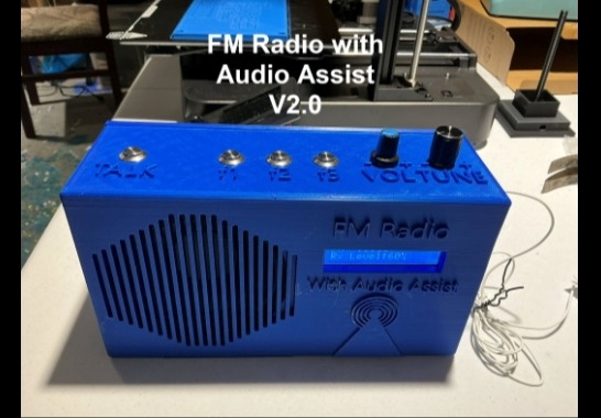
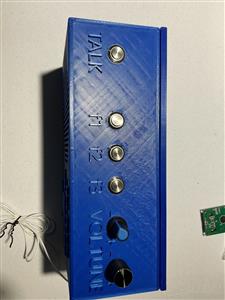
Custom raised lettering or indent next to each control to help the user (0.075" extruded/indented x 0.4" height raised/indented letters.
Absolute minimum number of controls and complexity.
Independent potentiometers to adjust radio volume, announce volume and beep volume.
Two rechargeable 3.7V lithium battery (7.4V in total) which will last for around 30+ hours depending on battery type used.
USB-C Power plug for charging and running the radio.
High quality mid-range speaker with great sound.
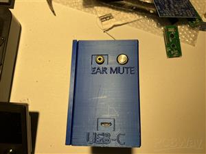
Earphone jack for 3 or 4 pin 3.5mm jack.
Loudspeaker Mute button.
Reasonably compact at 8.5" x 4.75" x 2.8" in size.
When tuned past the end of the useable range the tuning "wraps around". For example if you tuned it past 108.0 MHz to what would be 108.1MHz it wraps around to the bottom of the range and goes to 88.0 MHz and vice-versa.
Circuit Diagram:
The Circuit Diagram is attached. Some explanation is required here. The radio is powered by two 3.7V 18650 format Lithium batteries with a total voltage of 7.4V nominal. These batteries requires charging and conversion from 7.4V to 5V and 3.3V logic levels. The radio uses a stand alone MECCANIXITY Battery Charging Module Multi-Cell 2S 1A Type-C 8.4V which connects to the main PCB. It is powered through a USB-C connector, so it is mounted at the side of the radio case with a hole in the case that matches the USB-C connector. Note that Vin on the charger module is connected to P14 to bring +5Vin on the USB-C to the PCB.
Now this charging module operates as follows: When the battery is connected to it, it draws a few tenths of a milliamp of current. If left connected to the battery for long periods, it will drain the battery even if the radio is off. So SW1A disconnects it when the radio is switched off. When the USB-C cable is plugged in it will pass 7.4V+ to its output regardless of whether the battery is connected. This means that if you have the USB-C cable plugged in and the switch to the battery off, the radio will be on unless there is another switch to isolate the radio circuit from it's output. So SW1B disconnects the radio when the switch is off. This is the reason for the rather complicated looking circuit at the bottom left of the circuit diagram. This is also why the power switch is a DPST switch. SW1A connects/disconnects the battery and SW1B connects/disconnects power to the radio. They are ganged together so both are on or off at the same time. Transistor Q1 is there only as polarity protection. If by accident the batteries are inserted backwards, it will not conduct. Under normal conditions it conducts in both directions so the radio can receive power from the battery, and the battery can receive current from the charging module.
So if the radio is running on battery power alone; when SW1A/B is on, the battery is connected to the charging module and to the radio. The radio has power from the battery and the battery is not charging. If we turn switch SW1A/B off then the battery is disconnected from the module and the radio is disconnected from the module output, the radio is off and no power flows from the battery to the module either.
When the USB-C cable is plugged into the module with SW1A/B off, power from the USB-C supply activates relay K1, this connects the battery to the module for charging, this occurs because K1's contacts bridge SW1A. The radio remains off because SW1B is off but the battery is connected to the charging module. Here we use both sets of K1's contacts for more reliability and current carrying capability. D1 suppresses back EMF from the relay coil, it is critical to have it in place.
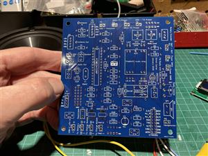
Note that I have each connection designated as a plug on the PCB e.g. P1, P2, P3 etc. If you want you could add plugs and jacks for these connections to the PCB. However I just solder wires directly to the PCB. Not only is this more reliable but it also saves the cost of all those plugs. It is however easier to use P1, P2, P3 etc. designation in the PCB design software as it makes it easier to create a footprint for each connection, so that's why I did it that way. I used "EasyEDA" design software to create the circuit and the PCB design.
Some other components: SW2 is the announce or talk button, when you press this it tells the microcontroller to read the current frequency setting and audibly announce it. SW7, the rotary encoder push button switch will also activate the announce function if pressed down momentarily. If you press and hold SW7 you will get a radio status report on the USB-C condition and the battery voltage. If you tune the radio to 107 MHz and press and hold the rotary encoder button you will get an audio rendition of the radio instructions. If you tune the radio to 108 MHz and press and hold the rotary encoder button you will get the Easter Eggs (Jokes).
SW3, SW4 & SW5 are presets. If you tune to a channel and press one of these for more than 3 seconds it writes that frequency in to permanent memory. Now if you momentarily press the button the radio goes to that frequency. These are reprogrammable at any time. By default, when you power on the radio it always tunes to the preset in preset number 1 set by SW3. The Mute button SW6 will mute the radio speaker if pressed, and unmute if pressed again. Even when muted, audio is still fed to the earphone jack. Pressing SW6 shuts of power to the audio amplifier via Q2.
The microcontroller constantly scans rotary encoder ROT1. If it is turned it changes the radio frequency in 100KHz steps as is the standard basic increment used in channel spacing in North America. The current frequency is displayed on the LCD along with the received signal level in %. 100% being perfect reception, although levels far below this are perfectly clear. The display also shows the battery level and logic level (+5V) voltages on the LCD momentarily on power on.
Header H1 can be used to program the microcontroller on board the PCB, if you have a programming dongle. If not plug your ATMEGA328P into an Arduino Uno or other standard Arduino board and program it there then transfer it to the PCB. Potentiometers RP2 and RP3 can be used to adjust the announce and audio beep/pip levels. Set these to midway and they should be just about right. I have left two small holes in the radio case above these pots, so they can be adjusted at anytime with a small screwdriver.
About the PCB:
Note I have made some design modifications to the current prototype PCB. The newest PCB design V2.0.1 is as yet untested.!! See the other sections for details on this and why changes were necessary.
You can find the 2.0.1 PCB Gerber files at this link:
https://drive.google.com/drive/folders/1QIe5QSbDlwYc4IhKJxvfnf5tmRK9pqgj?usp=drive_link
SYN6988:
The SYN6988 module does a good job of converting text to speech. It is a somewhat delicate module. So be careful with it. Critical Step: Make sure that you do not connect this module to +5V, it is a 3.3V module. Make sure you have R23 and R25 in place to reduce the +5V signals from the Microcontroller to a lower level.
There are 4 dip switches on the module for setting the Baud rate. Turn on switches 1 and 4 to set the baud rate to 9600, as per the table printed right on the SYN6988 PCB. Pins 4 and 5 of the microcontroller are set up in the software as a soft serial UART connection to the SYN6988 with 9600 baud rate specified. So it won't work unless you do this.
Note that in the software I'm using two methods to make the SYN6988 speak, one is to put short pieces of text in the void loop and then speak() function. This is convenient and fine for short text. Longer text takes up too much dynamic memory though. So the second method is to put long pieces of text in to program memory (PROGMEM) and then call them up using the Talk() function.
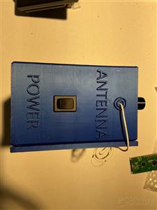
3D Printed Case:
This project uses a 3D printed radio case. Previously I had purchased generic plastic cases and they were expensive - usually in the $20 to $30 range. It was difficult to get the size I wanted and they don't look great. Drilling and cutting holes in them is very time consuming and it is hard to make it look nice. With 3D printing we can make a custom case with everything fitting properly and custom raised or indented lettering on the case for each control to help the user. Also it's much cheaper - anywhere from 75 to 80% cheaper! I had to make a couple of attempts with prototypes to finally get it right. You can see my prototypes in the video and pictures.
To design the radio case I used FreeCad. Although it is free and has great capability it has some issues. It is very buggy and slow, throws out a lot of error messages, is not intuitive to use and is very unforgiving. Be aware of this if you are going to use it. I have attached my FreeCad and other design files if you want to use them or make modifications. There are three sets of files, one for the case, one for the SYN6988 mount and one for the back panel or lid. I have also included the FreeCad export file or .STL file as well as the gcode file from the Prusa Slicer software. If you don't want to bother with all that just load the gcode file into your printer and print it. Be aware that it is a long print job depending on the resolution you pick. My radio case print took about 40+ hours at reasonably high resolution. Use higher quality PLA filament for a good result.
You can find the Files associated with the design and production of the 3D printed case at the following link:
https://drive.google.com/drive/folders/1QIe5QSbDlwYc4IhKJxvfnf5tmRK9pqgj?usp=drive_link
Calibration and Checks:
The Meccanixity battery charging module we are using is a 2S (7.4V) 1A module. Look at the back of the module you should see a black dot on 2S and a black dot on 1A. There are many different types of these modules that look the same, so make sure you have ordered the correct one. As a check, measure the voltage across the BAT and GND pins, you should measure something in the region of 7 to 8 volts DC. Measure Vin to GND, you should measure +5VDC. Do this check before connecting the module to anything.
Next calibrate the Announce and Beep/pip audio levels. You will need the radio completed to do this, so it is pretty much the last step. You can turn down the radio volume knob almost to zero while doing this procedure to make it easier to hear. While pressing the announce button to initiate an announcement adjust potentiometer RP2 at the top right of the PCB to a comfortable audio level. Approximately mid-way should be about right. Next while rotating the rotary encoder knob up and down, adjust potentiometer RP3 at the top right of the PCB to a comfortable audio level. Approximately mid-way should be about right. Next turn up the radio volume level to a comfortable level and initiate an announce and make sure you can hear it clearly. Same with the beep/pip level. If not adjust RP2 and RP3 accordingly.
Next calibrate the Arduino ADC reading of the battery level. This is required because R16 and R17 are necessary to isolate the Arduino ADC1 pin from the battery when the radio is off and to lower the battery voltage to a level below 5V when it is on. To do this first turn on the radio with the USB-C cable disconnected and then measure the present battery voltage with a DVM. This can be any value as long as it is above about 6.2 volts so the radio and Arduino are receiving sufficient power and voltage. Once you have this value, we'll call it Measured Voltage, record this value. Next turn the radio off and then turn it back on and see what the Battery Voltage says on the radio LCD screen at power on. This is the ADC Voltage as seen by the Arduino. Now determine a Correction Factor by dividing the Measured Voltage by the ADC Voltage. So Correction Factor = Measured Voltage/ADC Voltage. For example if the measured voltage is 7.9 Volts and the indicated ADC Voltage is 3.9 Volts then the correction factor is7.9/3.9 = 2.025. Next put this correction factor into the Arduino code on lines 232 and 753 (as of this writing) of the Arduino program. Save the program and load it into the ATMEGA328P.
Next calibrate the Arduino ADC reading of the +5V logic level on ADC0. To do this first turn on the radio with the USB-C cable disconnected and then measure the present logic level voltage with a DVM across the +5V rail to GND. Once you have this value, we'll call it Measured Voltage, record this value. Next turn the radio off and then turn it back on and see what the Logic Voltage says on the radio LCD screen at power on. This is the ADC Voltage as seen by the Arduino. Now determine a Correction Factor by dividing the Measured Voltage by the ADC Voltage. So Correction Factor = Measured Voltage/ADC Voltage. For example if the measured voltage is 4.85 Volts and the indicated ADC Voltage is 4.5 Volts then the correction factor is 4.85/4.5 = 1.077. Next put this correction factor into the Arduino code on line 219 (as of this writing) of the Arduino program. Save the program and load it into the ATMEGA328P.
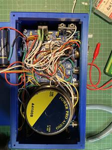
Installing the radio electronics in the case:
Install the switches in the case and leave enough wire length that you can connect and solder them to the PCB with the PCB out of the case. Solder the earphone jack wires to the earphone jack (audio+ goes to both L + R pins) and also solder the antenna wire in place. Use 1.5 meters of wire for this which is a half-wavelength at 100 MHz (mid-Band). Use DuPont jumpers to connect the LCD and SYN6988 to the PCB. I soldered the male end to the PCB and used the female end to connect to the LCD and SYN6988 pins just in case I needed to remove or replace them. This makes it easy. I used hot glue to ensure that the female ends of the Dupont jumpers don't slip off the pins on the modules easily. So, place the LCD screen in place next and use hot glue to hold it in place if required.
Screw and glue as required the Charging module to the shelf next to the USB-C access port. Once the PCB is fully wired up, install it on the PCB posts provided and screw it down. Next solder the speaker wires to the speaker and install it and screw it down. Next glue to SYN6988 holder to the back panel. Screw the SYN6988 module to this holder. Glue the battery holder box to the back panel also and in all cases let the glue dry as specified by the brand you are using. Make sure all wires are out of the way of the path between the back panel and the PCB pots for adjusting the announce and beep audio levels. Tie wires back with cable ties as needed. Place the back panel on the radio and screw in place with the 4 corner screws. Installation is complete.
Arduino Code:
The Arduino code is fully commented. You should be able to mostly follow it. It uses the following libraries to control the radio module, LCD, speaking announcements etc. You need to place these in your own library using the Arduino Library Manager.
#include <SoftwareSerial.h>
#include <LiquidCrystal_I2C.h>
LiquidCrystal_I2C lcd(0x27,16,2);
#include <TEA5767.h>
#include <tea5767_core.h>
#include <Wire.h>
#include <EEPROM.h>
CRITICAL STEP:
You need to load the Arduino program for this project into the ATMEGA328P twice. The first time you do, you MUST uncomment line 170 (as of this writing) of the program so that this code is active. This is the first line in the Void setup {}. This line is:
//EEPROM.put(0, 99.1); EEPROM.put(10, 98.1); EEPROM.put(20, 97.3); //To PREPROGRAMME THE PRESELECTS USE THE FIRST TIME YOU PROGRAM THE ATMEGA 328P then reprogram without this line.
What this does is pre-program some useable frequencies into the pre-select button memory locations. Remember that on power up the radio draws its frequency information from the frequency in pre-select 1 or EEPROM location 0. If there is nothing in there it will draw a blank and no frequency will be programmed into your radio and it won't work, you will not see a frequency displayed on the LCD either.
Once you have done this, then comment out line 170 (as of this writing) again and reprogram your ATMEGA328P a second time. Now that you have a dummy starting value for the frequency in memory you do not want to continuously write to memory every time the radio powers up, which is what will happen if this line is left active. The reason for this is that the ATMEGA328P only has so many read/write cycles to EEPROM memory before read/write ceases to function. The number of cycles allowed is huge but nevertheless will eventually run out. (about 100,000 cycles allowed)
Once you have done this the radio will have a default frequency to use on startup. From now on you may change the pre-set frequencies anytime you like by tuning to the frequency you want and holding down the pre-set button for more than 3 seconds.
Issues, Corrections, Redesign, Future Updates:
This was a difficult project for me. It seemed like a lot of the time it was one step forward and two steps back. I confess to being quite frazzled at the end of it. However I learned a lot doing it, I enjoyed it and I view it as continuous improvement and learning project.
Reasons for this are that the SYN6988 has no library publicly available and very little in the way of example code. Also it is a delicate module and I managed to kill a couple of them before I got it right. Also I'm not very experienced at designing analog audio circuits or PCBs. And I am new to 3D printing as well. On top of that I probably made the radio case too small. It was very difficult to cram everything in. Let me go through the issues and the plan to correct these:
SYN6988:
I either killed a couple of these by shorting them out by accident, over voltage on the supply or maybe bad software commands. Probably all 3. Anyway in future I plan to use the software I developed here to run these without too many changes, and they will be the very last item I connect to the circuit to prevent accidents. I will also wait until the very last moment to finally connect the battery to prevent any accidental shorts while doing installation. Enough said. The SYN6988 is now working reliably and safely with the electrical connections and software I have.
3D Case:
The 3D case as it is right now is about as compact as it can get. This is great for the user, smaller is better, but it makes for a very difficult build. Although quite serviceable, it is probably just too compact in the present form. It was really difficult to get the PCB and speaker into the case without contacting and in some cases bending switch contacts etc. Also the raised letters on the case were an issue. When printing supporting material is added which is darn near impossible to remove without either scratching the case or damaging the letters.
I'm planning on redesigning as follows: I'll make it larger in height and width to make it easier to install everything. I can't make it longer as my printer won't accommodate a larger size, but that won't be necessary. I'll increase the height of the PCB posts to make more room under the PCB for the LCD which is currently a very tight fit too. I'll make some of the lettering indented instead of raised to get rid of the excess support material issue.
PCB:
So PCBWay did a lovely job of making the PCB, but as I outlined in the video I had several issues due to my design of the PCB. The Battery power, +5V and Ground traces were too thin and switch contacts were located too far away. As a result there was enough impedance that when the power was turned on the initial surge of current caused a big enough voltage drop to stall the microprocessor during initial set up. I have solved this temporarily by soldering thicker wires across the thin traces, changing the charging/boosting module, increasing the battery voltage and adding a voltage regulator. Initially I had also added R22 and R28 to provide some control over inrush current. I'm not sure that these are required with all of the design changes, but it does not hurt to leave them in place for now in case they are needed. If not 0 ohm resistors or wire can be used. All this means that I have modified my current PCB and designed a V2.0.1 PCB with current fixes. I will provide you with the V2.0.1 Circuit and PCB design with these fixes, but please be aware that I have not had a chance yet to have this PCB manufactured or test it out, so you might want to wait for me to do that. Otherwise you are on your own with respect to getting it working if there are any issues.
Link to PCB Files:
https://drive.google.com/drive/folders/1QIe5QSbDlwYc4IhKJxvfnf5tmRK9pqgj?usp=drive_link
Circuit Design:
The circuit design issues here were to do with the power system, the audio amplifier control and the radio, announce and earphone audio level balance. I have already discussed the issues and fixes to do with the power supply. One last thing to mention here is that with the temporary fix to the existing PCB I used an LM7805 voltage regulator, but they are expensive and the have a drop out voltage of 2 Volts. In the revised design I'll use an AMS1117-5.0 which is much less expensive, more efficient and has a drop out voltage of 1.2 Volts. Using this component is also yet to be tested. However I can't think of any reason why it won't work.
Using a 2N2222A transistor to lift the ground on the audio amplifier module to mute the loudspeaker was not working well and it was distorting the audio somewhat. Strangely this worked okay on the breadboard, but not on the PCB. I have changed this part of the design to use a BSP250 FET to switch on/off the +5V supply to the audio amplifier and this works perfectly.
The radio audio is perfectly serviceable. But there are issues with the audio mixing levels of radio audio, SYN6988 audio and beep/pip sound, so even with adjustment pots they are uneven in audio level. So the announcement may be loud, but then when it is done, the radio volume sounds low and then the beep sound is much too high etc. So these are not too well balanced right now. On top of that the earphone level is much lower than the others unless you turn the volume knob right up. Plugging in earphones also affects the speaker audio level. So I want to rework that part of the circuit. Possibly I can use the other channel of the audio amplifier which is currently unused and possibly an active circuit for mixing.
I plan to try an improve all this in the next major revision which will be V2.1.
Stay tuned for further updates in V2.1. !!!
Other Associated files:
Find other related files and pictures at this link:
https://drive.google.com/drive/folders/1QIe5QSbDlwYc4IhKJxvfnf5tmRK9pqgj?usp=drive_link
I'm also posting a detailed overview of the design, almost exactly the same as this on Instructables at:
FM Radio With Audio Assist for the Visually Impaired (Version 2.0) : 12 Steps - Instructables
Thank you for considering my design for the 8th design contest.
Best Regards,
Simon Carter
FM Radio with Audio Assist for the Visually Impaired
Project images are for reference only. Actual production is based on the manufacturing files on the project page.
Please review the designer's notes (e.g., PCB thickness) and select the appropriate options.
PCBWay is not responsible
for issues caused by unsuitable parameter selections.
For more important ordering information, please refer to
Read More


Raspberry Pi 5 7 Inch Touch Screen IPS 1024x600 HD LCD HDMI-compatible Display for RPI 4B 3B+ OPI 5 AIDA64 PC Secondary Screen(Without Speaker)
BUY NOW

- Comments(0)
- Likes(0)
- 1 USER VOTES
- YOUR VOTE 0.00 0.00

-
9design
-
10usability
-
10creativity
-
10content
More by Simon Carter
-
Programmable Mist Maker - XIAO / QT PY Extension
1061 2 1 -
RadioHAT - Raspberry Pi radio development platform
861 0 2 -
-
-
-
-
ARPS-2 – Arduino-Compatible Robot Project Shield for Arduino UNO
3322 0 6 -
A Compact Charging Breakout Board For Waveshare ESP32-C3
3930 3 8 -
AI-driven LoRa & LLM-enabled Kiosk & Food Delivery System
4316 2 2


