



|
|
EasyEDA |
|

|
Fusion 360Autodesk
|
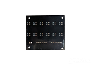
Endstops Breakout Board
If you've ever wired more than two or three limit switches to a microcontroller, you already know the pain: a rat's nest of resistors, a breadboard that shakes loose the moment the machine starts moving, and, worst of all, endstops that trigger randomly because of electrical noise picked up next to your motor cables.
I hit this exact wall while working on a multi-axis project that needed six independent axes, each with its own Min and Max limit switch Instead of dead-bugging resistors and capacitors onto a protoboard one more time, I designed a small, dedicated interface board: raw digital pins go in on one side, twelve clean, ready-to-wire endstop connectors come out the other.
Here's how it works, and why it's built the way it is.
The problem with wiring endstops directly
A limit switch is about as simple as electronics gets: two contacts that either touch or don't. But that simplicity hides two real problems the moment you connect one straight to a GPIO pin:
- Floating input. When the switch is open, the pin isn't connected to anything — it "floats," picking up whatever noise is nearby and reporting random highs and lows. You need a pull-up (or pull-down) resistor to give the pin a defined default state.
- Contact bounce. Mechanical contacts don't close cleanly — they physically bounce for a few milliseconds before settling. Electrically, that looks like a burst of rapid on/off transitions instead of one clean edge. Left unfiltered, your firmware can register a single switch trigger as five or six.
The usual fix is software debouncing, but with six axes and twelve switches, I'd rather solve the problem once, in hardware, and let the firmware just call digitalRead() and trust the result.
The circuit: pull-up + low-pass filter
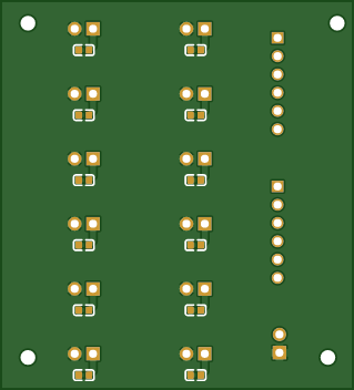
The schematic is deliberately boring and that's the point. Every channel repeats the exact same three-component pattern:
- A 10 kΩ resistor from +5V to the signal line, holding the pin HIGH by default.
- A 100 nF capacitor from the signal line to GND, forming a simple RC low-pass filter together with the pull-up resistor.
- The switch itself, wired between the signal line and GND: when it closes, it overpowers the pull-up and pulls the line LOW.
With R = 10 kΩ and C = 100 nF, the RC time constant works out to roughly 1 ms (τ = R × C). That's more than enough to smooth out the few-millisecond bounce of a typical mechanical switch, while still reacting fast enough for real-time homing routines.
In my case those headers go straight to an Arduino, but there's nothing Arduino-specific about them: any microcontroller with input pins and a 5V rail works exactly the same way.
From schematic to layout
The layout mirrors the schematic's simplicity on purpose:
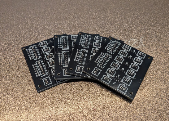
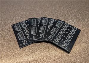
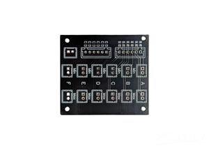
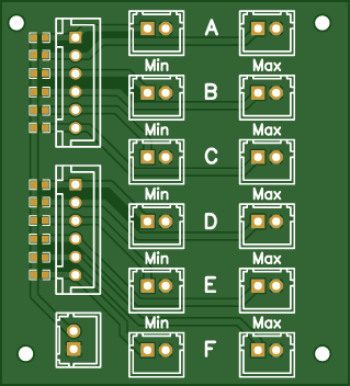
- Input side (left): two multi-pin headers carrying the twelve signal lines, plus a small 2-pin header for the +5V/GND supply that powers all twelve pull-ups.
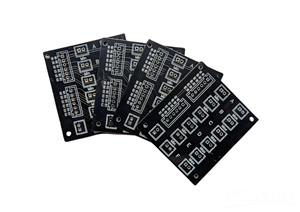
- Output side (right): twelve individual 2-pin connectors, clearly silkscreened A through F, each split into a Min and a Max pair.
- Four corner mounting holes so the board can be screwed straight into an enclosure or machine frame.
Two layers are all this circuit needs: with only DC power and a handful of low-frequency digital lines, there's no reason to reach for anything fancier.
Wiring it up
Using the board is meant to be close to plug-and-play:
- Connect the two input headers to digital input pins on your controller.
- Connect the power header to +5V and GND.
- Wire each mechanical endstop switch to its labeled Min or Max connector.
- In firmware, set each pin as INPUT and read it: LOW means triggered, thanks to the pull-up.
Wrapping up
Sometimes the most useful board isn't the cleverest one: it's the one that turns a repetitive, error-prone wiring job into a five-minute plug-in task.
The schematic and PCB files are attached to this post: feel free to adapt the pin count or the resistor/capacitor values to your own setup. If you'd have designed it differently, I'd love to hear about it in the comments.
If you're into robotics builds like this one, come find more projects and courses at learnbydoing.dev.
Endstops Breakout Board
Project images are for reference only. Actual production is based on the manufacturing files on the project page.
Please review the designer's notes (e.g., PCB thickness) and select the appropriate options.
PCBWay is not responsible
for issues caused by unsuitable parameter selections.
For more important ordering information, please refer to
Read More









Raspberry Pi 5 7 Inch Touch Screen IPS 1024x600 HD LCD HDMI-compatible Display for RPI 4B 3B+ OPI 5 AIDA64 PC Secondary Screen(Without Speaker)
BUY NOW


- Comments(0)
- Likes(0)
More by Francesco Brandi
-
SmallOLED - Live PC Stats, Animated Clocks & Audio Visualizer
756 0 3 -
"Talking Multimeter": Arduino-Based Speech Add-on for Multimeters with SCPI Protocol
429 0 1 -
Programmable Mist Maker - XIAO / QT PY Extension
2881 2 3 -
RadioHAT - Raspberry Pi radio development platform
2463 0 4 -
-
-
-
ARPS-2 – Arduino-Compatible Robot Project Shield for Arduino UNO
4547 0 6


















