



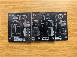
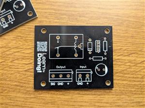
DIY Relay Oscillator
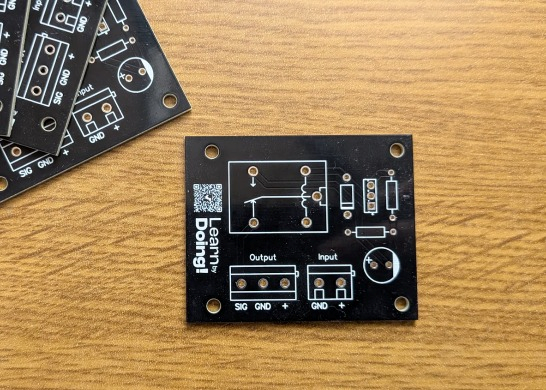
Hi everyone! I’m sharing a classic Relay Oscillator Circuit designed to continuously toggle an external output between VCC and GND.
Unlike a standard timer, this circuit features a clever feedback loop connected to the relay's internal switches (K1).
How it works:
- The Charging Phase: When power (VCC) is applied, the C1 (220uF) capacitor charges through R1 (4.7kohm).
- The Trigger: As soon as the voltage is high enough, it triggers the NPN power transistor Q2 (BD435) through R2 (2.2kohm), activating the relay coil.
- The Feedback Loop: When the relay switches, the internal contact connected back to the RC network alters the capacitor's state (discharging it or cutting the latch). This immediately turns off the transistor, releasing the relay and restarting the whole cycle.
- Protection: A 1N4004 (D1) flyback diode is placed across the coil to suppress voltage spikes and protect the transistor.
- Output: The result is a continuous, automated switching wave at the OUT terminal block, perfect for flashing lights, automated testing, or cycling loads.
You can easily adjust the oscillation frequency (speed of the switching) by experimenting with different values for C1 and R1.
Feel free to download the Gerber files and let me know your thoughts in the comments!
DIY Relay Oscillator
Project images are for reference only. Actual production is based on the manufacturing files on the project page.
Please review the designer's notes (e.g., PCB thickness) and select the appropriate options.
PCBWay is not responsible
for issues caused by unsuitable parameter selections.
For more important ordering information, please refer to
Read More









Raspberry Pi 5 7 Inch Touch Screen IPS 1024x600 HD LCD HDMI-compatible Display for RPI 4B 3B+ OPI 5 AIDA64 PC Secondary Screen(Without Speaker)
BUY NOW


- Comments(3)
- Likes(0)
More by Francesco Brandi
-
SmallOLED - Live PC Stats, Animated Clocks & Audio Visualizer
756 0 3 -
"Talking Multimeter": Arduino-Based Speech Add-on for Multimeters with SCPI Protocol
429 0 1 -
Programmable Mist Maker - XIAO / QT PY Extension
2881 2 3 -
RadioHAT - Raspberry Pi radio development platform
2463 0 4 -
-
-
-
ARPS-2 – Arduino-Compatible Robot Project Shield for Arduino UNO
4547 0 6


















