


|
|
M-1-N16R8 ESP32-S3-WROOM-1-N16R8 |
x 1 | |
|
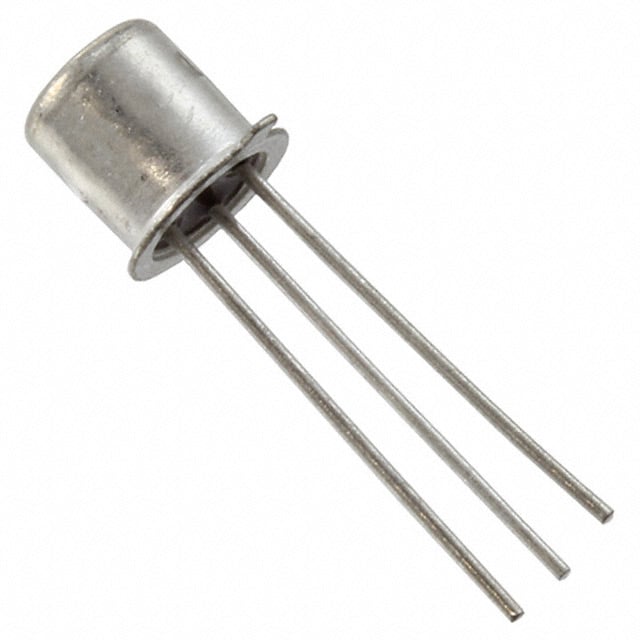
2N2222AMicrochip Technology
|
x 22 | |
|
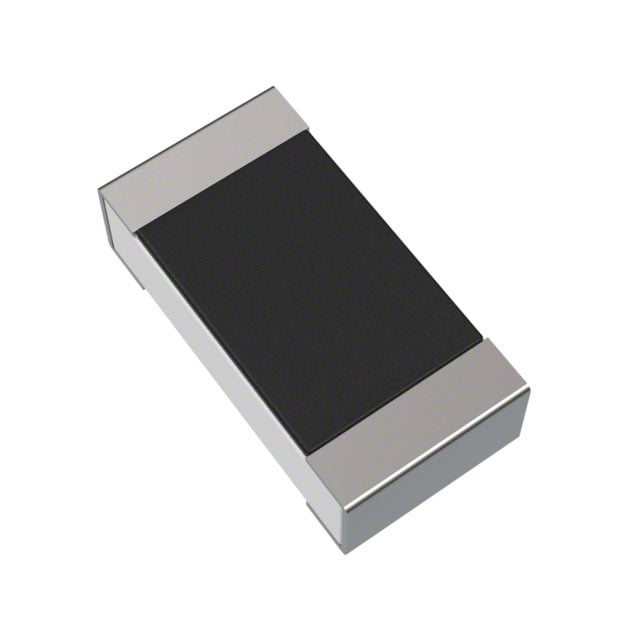
RC1206FR-07680RLYAGEO
|
x 22 | |
|
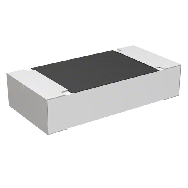
ERA-8AEB470VPanasonic Industry
|
x 44 | |
|
SM5730UWDC05Bivar Inc.
|
x 44 |

|
KiCADKicad
|
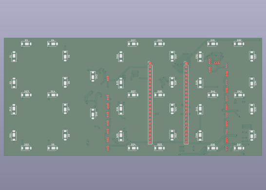
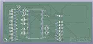
ESP32-Powered Digital Clock
A pretty simple ESP32 powered clock, intended to be used in combination with a 3D printed enclosure/diffuser. I haven't gotten the board made yet, so the enclosure files aren't ready, but I will add them once I make them. This board is intended to be used with an ESP32-S3 dev board, my specific board is an N16R8 board (random amazon board, with two USBC ports), but as long as you have an S3 board that fits the dimensions, it should work just fine. All the stuff needed for it to work is included in the BOM, aside from an optional SMD pushbutton. This isn't necessary, but you can include it. All it does is pull RST to GND, and reset the ESP32. You could also just do this by power-cycling though.
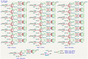
I would recommend making this board with black solder mask, since it is FR4, and the 5730 LEDs get pretty hot. (That's why the entire board is covered in copper pours). As for ESP32 code, that again isn't ready yet since I haven't made the boards. But it is pretty simple, and you could make your own program easily using the schematic files that are attached. I didn't want to mess around with shift registers, so each segment is just wired to a GPIO pin, through a transistor, meaning you can just turn the desired GPIO pins on or off to display the time. Again, all the wiring is shown in the schematic, along with which segment it corresponds to.
Assembly notes:
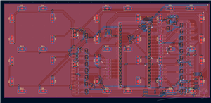
This board uses several through the hole components: the transistors, and the ESP32. I have yet to see an ESP32 dev board that has exposed connections alongside that allow it to be used without headers (Look at a Pi Pico to understand what I'm talking about) so I have to put the pins through the board in order to attach it. Since this is intended to be completely covered by a diffuser, it doesn't matter a lot, but I would recommend soldering all THT components as close to flat as possible. In the case of the transistors, it is easy to cut them, but the ESP32 needs to be held at the right level by propping up the board, and then soldering it on. Many of the ESP32 pins are non-connect as well, (Marked by an "X" on silkscreen) you don't need to solder them, unless you want them for structural support. As for the transistors, orient them in the way suggested by the silkscreen (flat side towards the line), and you'll be fine. The square shaped pad is NOT ground, it is the collector. The LEDs are also self explanatory, with the pad placement, but GND will always be towards the silkscreened "U" shape, with the positive being the pad away from the silkscreen. The middle thermal pad is wired to 5V, and IS connected to it. If your LEDs have a thermal pad that is wired to ground for some reason, they will create a short, so make sure you have normal LEDs. Finally, there are no power/ground pads, wire the power and ground to the 5VIN pin, and one of the GND pins to provide power to the board.
ESP32-Powered Digital Clock
*PCBWay community is a sharing platform. We are not responsible for any design issues and parameter issues (board thickness, surface finish, etc.) you choose.


Raspberry Pi 5 7 Inch Touch Screen IPS 1024x600 HD LCD HDMI-compatible Display for RPI 4B 3B+ OPI 5 AIDA64 PC Secondary Screen(Without Speaker)
BUY NOW


- Comments(0)
- Likes(0)
 More by Engineer
-
Programmable Mist Maker - XIAO / QT PY Extension
752 1 0 -
RadioHAT - Raspberry Pi radio development platform
600 0 1 -
-
-
-
-
ARPS-2 – Arduino-Compatible Robot Project Shield for Arduino UNO
3083 0 6 -
A Compact Charging Breakout Board For Waveshare ESP32-C3
3696 3 8 -
AI-driven LoRa & LLM-enabled Kiosk & Food Delivery System
3987 2 2


