


|
SolidWorksSolidWorks
|
|

|
arduino IDEArduino
|
|

|
MatlabMatlab
|
|

|
Proteus 8 |
Design of a Delta Robot Model combined with a PID Controller
1. Introduce
The project is fully titled "Research and Development of a Delta Robot Model Combining PID Controller to Optimize Accuracy and Speed During Operation" . Specifically, PID aims to optimize accuracy and speed during operation. The structure, kinematics, and mechanical design were studied using SolidWorks software; the control system was implemented with an Arduino microcontroller, stepper motor drivers, and encoder sensors; the PID algorithm was simulated in MATLAB/Simulink and calibrated for each axis. Experimental results showed that the robot operates with very small steady-state error (error < 0.5), with an average settling time of approximately 2.32 seconds. The model achieved stable trajectory tracking speed in seconds; experiments running to the set coordinates and plotting circular trajectories showed close adherence to the desired trajectory. Specifically, each experiment was calibrated with different PID parameters for optimal performance, with a sampling time of 0.01 seconds identified as the most suitable, resulting in a good balance between accuracy, response speed, and stability. The model is fully applicable for educational and teaching purposes.
1.1 Research objectives
The objectives of this research project are as follows:
- Successfully researched and developed a Delta Robot model.
- Communicate with and control the Delta robot model in real time using MATLAB/Simulink software.
- Develop a PID controller using MATLAB/Simulink software.
- Integrating a PID controller into the Delta Robot model optimizes accuracy and speed during operation. Design and fabrication methodology.
Mechanical design:
- Building a 3D model of the Delta robot using Solidworks software.
- The detailed design includes the following components: fixed base, active arm, passive arm, joint, and working platform.
- Choose the right materials to ensure rigidity, lightness, and reasonable cost.
Control system design:
- The control system block diagram design includes: microcontroller, stepper motor driver, encoder sensor, and power supply.
- Design schematics and printed circuit boards (PCBs).
Software control design:
- Programming to control a stepper motor and read the angle sensor using the Arduino IDE.
- Implement the PID algorithm for each axis in MATLAB/Simulink.
1.2 Research task
To achieve the research objectives, several tasks have been set as follows:
- Design a 3D model of the Delta robot.
- Assemble and test the actual model.
- Design the control system and electrical circuits.
- Programming combined PID control in MATLAB/Simulink.
- Adjust and optimize PID parameters.
1.3 Novelty and innovation
- Incorporating PID control into the Delta robot model improves operational accuracy and stability, a capability that many basic models have not effectively achieved.
- The Delta robot model is designed as a practical industrial simulation tool, applicable in engineering training, helping students access modern robotics technology.
- The model is built using common, low-cost components, while still ensuring scalability and integration with modern control technologies.
- The control algorithm is optimized using real-world feedback from the angle sensor, increasing the accuracy of terminal positioning.
- Its versatile applications in various fields such as picking, sorting, or high-speed 3D printing open up potential for model improvement and commercialization.
1.4 Kinematics problem
The Delta robot is a type of robot with a three-joint rotary structure, each arm having a RUU structure, where "R" stands for rotary joint (Revolute) and "U" stands for joint. Universal. Each arm of this robot maintains parallelism between two plates: a fixed plate and a movable plate, with the movable plate containing the end effector. Drive motors are located on the fixed plate and control the rotary joints R, generating rotational movement for the robot arms. The three rotary joints are denoted as theta i with i = 1, 2, 3, and these values are determined by the right-hand rule, with the positive direction of the rotation angles measured from the horizontal plane.
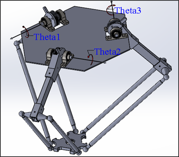
Rotary joint mechanism of the Delta robot
When the angle is theta i = 0, the rotating joints of the mechanism lie in the horizontal plane, which is the basis for determining the rotation angles and movement of the robot. The robot's mechanism uses a system of bars forming a parallelogram, with three basic links at the bottom to maintain the translational movement of the movable plate. The universal joints (U) are made up of three rotating joints R, not located at the same point, with a structure of two parallel joints and one perpendicular joint, creating a total of six universal joints, which help control the precise movement of the robot in the workspace.
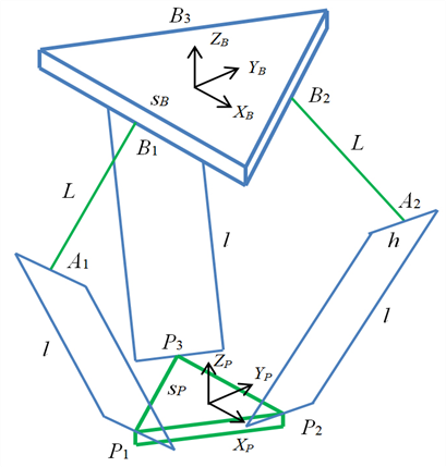
This Delta Robot has three degrees of freedom ( DOF ), allowing it to move translationally in space along the xyz axes. The kinematics of the Delta Robot involve determining the position and movement of the movable plate through rotary joint angles and mechanical linkages. The kinematic model is built upon the same RUU joint chain , with each chain analogous to the joints in the human leg structure, having the following articulation points:
- Hip joints: Bi with i = 1, 2, 3.
- Knee joints: Ai with i = 1, 2, 3.
- Ankles: Pi with i = 1, 2, 3.
The robot's structure consists of two equilateral triangles: one fixed on the fixed plate and one movable on the movable plate. The sides of the movable plate triangle are in the opposite direction to those of the fixed plate triangle, creating a special geometric relationship between the two plates. The equilateral triangle on the movable plate has sides in the opposite direction to the equilateral triangle on the fixed plate, with their shapes maintaining a constant ratio throughout the robot's movement.
Through this kinematic model, the problem is to determine the position and movement of the movable plate based on the rotation angles of the joints. This includes calculating the angles theta i with i = 1,2,3 so that the movable plate can move precisely to the desired position in the workspace, thereby controlling the robot to perform tasks such as assembly, packaging, or other automated jobs.
The kinematics problem of the Delta Robot involves using analytical methods to determine the relationship between the rotational joint angles and the position of the movable plate, ensuring smooth and precise movement in three-dimensional space. The geometric parameters of the fixed and movable plates will be used to construct kinematic equations, enabling the simulation and control of the robot in real-world applications.
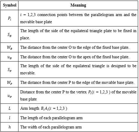
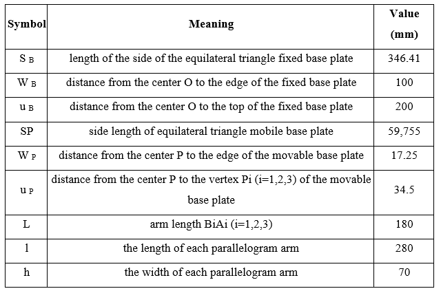
Geometric parameters
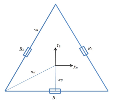
Fixing plate
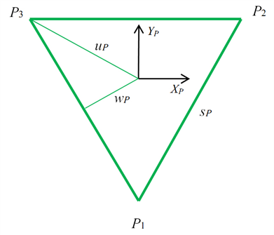
Mobile panel
Table : Geometric parameters
Coordinate system and articulation points of the Delta Robot
Cartesian coordinate system attached to the fixed plate is denoted by {B}. The Cartesian coordinate system attached to the movable plate is denoted as {P}, with its origin located at the center of the equilateral triangle on the fixed plate.
The coordinate system {P} always has the same orientation as the coordinate system {B}, therefore the rotation matrix

is constant.
Key kinetic components:
- Joint complications:
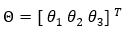
These are the rotation angles at the drive joints on the fixed plate.
- Cartesian variables:
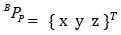
is the coordinate of the center of the moving plate {P} in the coordinate system {B}.
Joint points:
- Fixed pivot points ( Bi ): These are the positions of the pivot points on the fixed plate. Since the fixed plate does not move, the points are fixed in the base coordinate system {B}.
- The joint points of the movable plate ( Pi ): These are the positions where universal joints (U-joints) are attached to the movable plate. In the {P} coordinate system, these points are also considered fixed because the movable plate is a rigid body.
Symmetry in design:
The Delta robot has a highly symmetrical design, with: Upper arm length (L), Lower arm length (parallelogram structure: l ).
The geometric parameters of the fixed and movable plates play a crucial role in determining the relationship between the joint variables and the spatial position (x,y,z) of the movable plate.
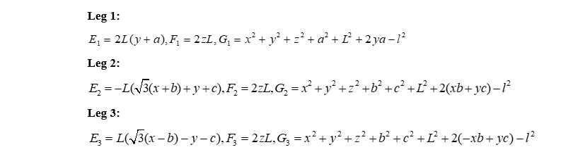
We have:
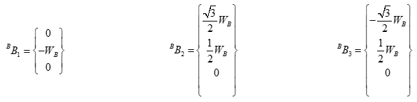
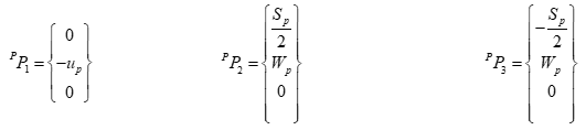
The vertices of the equilateral triangle of the fixed plate are:
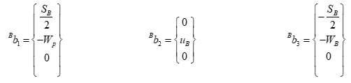
With:

1.5 PID algorithm
1.5.1 Introduction to the PID algorithm
The Proportional-Integral-Derivative (PID) algorithm is one of the most popular control tools in the field of automation and control. PID is highly regarded for its ability to balance response speed, accuracy, and system stability. It is a fundamental method widely applied in many engineering applications, especially in systems requiring precise control and rapid response, such as temperature, speed, and position control.
PID belongs to the feedback control group of methods, operating by continuously calculating the error between a preset value ( setpoint ) and the actual output value , then adjusting the control signal to minimize this error. The goal is to make the output quickly, accurately, and stably track the desired value, even in the presence of noise or load changes.
1.5.2 Structure basic structure of PID
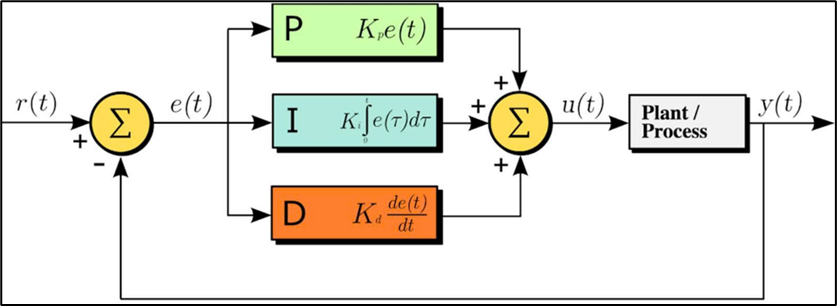
Figure : PID controller architecture
The PID controller consists of three main components, each playing a specific role in regulating the system:
- P-Component – Proportional: The proportional component generates a control signal directly proportional to the instantaneous error between the actual output and the preset value. This component helps the system react quickly to deviations; however, if the gain coefficient Kp is too large, it can cause oscillations and instability.

- Component I – Integral: The integral component accumulates the error over time, aiming to eliminate steady-state error that the proportional component cannot fully handle. However, if the Ki coefficient is too large, the system may become slow and prone to oscillation.

- The D-Derivative component reacts to the rate of change of the error, helping to predict the trend of variation and minimize system oscillations. This component is particularly useful in improving stability, but is too sensitive to measurement noise if the Kd coefficient is set too high.

- The general formula for PID:
The combined control signal from all three components is represented as follows:
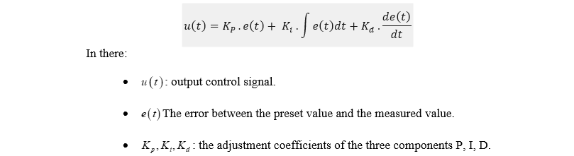
This structure allows the PID controller to achieve a balance between response speed, accuracy, and stability, making it widely used in many industrial and civil control systems.
1.5.3 PID application in Delta Robot control.
The application of PID control in Delta Robot control for position stabilization is one of the important methods to ensure that Delta Robots can accurately maintain and adjust the position of their end effectors in three-dimensional space. PID helps improve the accuracy and stability of the system, especially in dealing with factors such as motor errors, friction, and load changes.
Factors affecting the position control of Delta robots:
- Position error : As the Delta robot moves, there will be a difference between its actual position and its target position (desired coordinates). If left uncorrected, this error will accumulate and affect the robot's accuracy.
- Oscillation and vibration : When robots move quickly, oscillation or vibration may occur, especially when mechanical components are not optimized or when there are sudden changes in load.
- Friction and lag : During movement, friction between mechanical parts can reduce the robot's accuracy. The system may also experience lag in response from the motors.
-
1.6 MATLAB / Simulink : Model-based simulation and design environment Overview
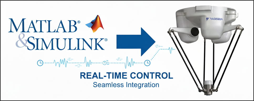
Figure : MATLAB / Simulink software
Simulink is a MATLAB extension specifically designed for building and simulating dynamic systems using block diagrams. Developed by MathWorks, it supports system-level design, simulation, automated code generation, and continuous testing and verification of embedded systems. Simulink provides a graphical editor, customizable block libraries, and solvers for modeling and simulating dynamic systems. It integrates seamlessly with MATLAB, allowing users to incorporate MATLAB algorithms into models and export simulation results to MATLAB for further analysis.
Simulink provides a powerful set of capabilities for system development:
- Model-Based Design (MBD): Simulink is at the heart of MBD , a systematic approach to developing complex systems. This includes using virtual models for early and frequent simulation and testing, validating the design with physical models, Hardware-in-the-Loop (HIL) testing , and rapid prototyping. It can also generate production-quality C, C++, CUDA, PLC, Verilog, and VHDL code for direct deployment to your embedded system.
- System Modeling and Simulation: Users can design dynamic system models and quickly evaluate multiple design ideas in a single multi-domain simulation environment. It supports large-scale system models with reusable components and libraries.
- Automated code generation: Generate production-quality C, C++, CUDA, PLC, Verilog, and VHDL code for direct deployment into embedded systems.
- Verification, Validation, and Testing: Supports continuous testing and verification of embedded systems. Helps maintain a traceable digital flow through requirements, system architecture, component design, code, and testing.
- Agile system development: Support agile software development by shortening development cycles through simulation, automated testing, and code generation, enabling teams to deliver value faster.
- Parallel simulation and cloud capabilities: Enables running large simulations on multi-core desktops, clusters, and the cloud, as well as running thousands of simulations in parallel.
- Hardware support: Supports third-party hardware such as Arduino, Raspberry Pi, Android devices, Parrot Minidrones, and LEGO Mindstorms.
- Creating blocks and block sets: Users can create custom blocks and reusable block sets to extend modeling functionality.
2. System design
2.1 System Overview
The system uses a distributed control architecture with MATLAB/Simulink on the host computer as the central hub. Here, users define the trajectory, while Simulink calculates PID control, performs simulations, and monitors.
Control signals are sent via UART to the Arduino Mega, which acts as an intermediary controller. The Arduino Mega then instructs the Shield V3 to run the stepper motor. To create a closed-loop control system, an Arduino Nano reads rotational angle data from the AS5600 sensor via I2C and sends it back to the Arduino Mega. This data is then sent back to Simulink by the Mega for updating and correction.
Simulink acts as the computing brain, while Arduino Mega serves as a bidirectional bridge, receiving control commands and sending sensor data back, creating a flexible and precise closed-loop control system.
2.1.1 Analysis of distributed architecture options
Choosing a multi-microcontroller architecture (Mega, Uno, Nano) instead of a single powerful microcontroller ensures real-time performance and modularity. Theoretically, an Arduino Mega 2560 board has enough I/O pins to directly manage all three motors and three sensors. However, simultaneously performing multiple tasks with varying time requirements on a single processor presents significant performance challenges.
Generating three independent, high-frequency, and latency-free pulse sequences for stepper motors is an extremely time-sensitive operation. Any interruption in the pulse generation process, even by just a few microseconds, will result in jerky, inaccurate robot movement, severely degrading the effectiveness of the PID controller. If the Arduino Mega has to simultaneously handle bidirectional serial communication with and manage data sampling from sensors, the risk of small interruptions in the motor control signals is very high.
By delegating motor control tasks to a pair of Arduino Uno and a dedicated CNC Shield, the Arduino Uno can focus entirely on executing high-level motion commands received from the Mega. It can utilize optimization libraries such as AccelStepper. To create pulse sequences with smooth acceleration, uninterrupted by other tasks.
Similarly, dedicating an Arduino Nano to collecting data from three AS5600 sensors via an I2C multiplexer ensures that sensor data is collected consistently and can be preprocessed if needed. This frees the Arduino Mega from having to manage the complex details of the low-level I2C protocol and allows it to focus on its primary orchestration role.
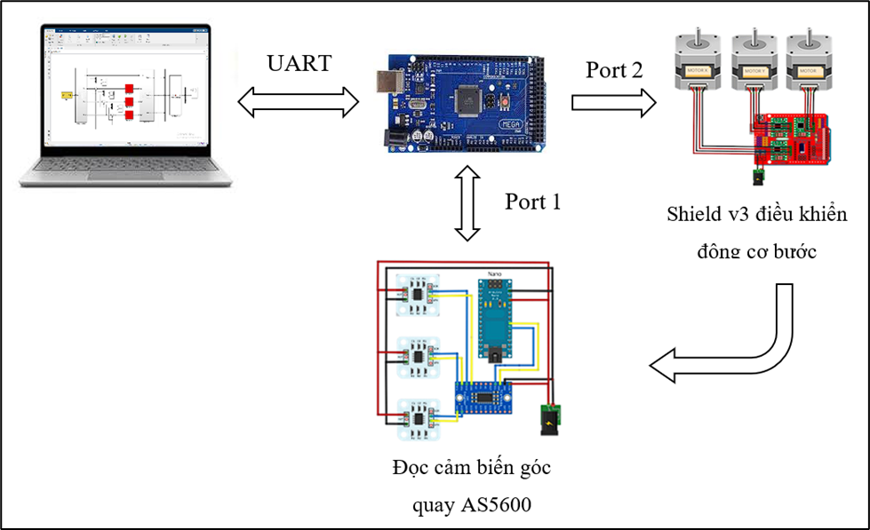
Figure : Schematic diagram of the PID control model for the stepper motor of the Delta Robot .
Control loop
The system operates in a closed-loop control system managed by the PID controller in Simulink. The process unfolds as follows:
- Simulink: Compares the desired angle (Setpoint) with the actual angle (feedback) to calculate the control signal (number of steps for the motor).
- Sending commands: This signal is transmitted from Simulink to Arduino Mega via UART, after which Mega commands the stepper motors to operate.
- Gathering feedback: At the same time, the Arduino Nano reads the actual rotation angle from the sensor and sends it back to the Arduino Mega.
- Loop completion: Mega transmits this feedback data back to Simulink to begin the next computation cycle.
This continuous, repetitive cycle ensures that the robot is always calibrated to move precisely along its predetermined trajectory.
2.1.2 System block diagram
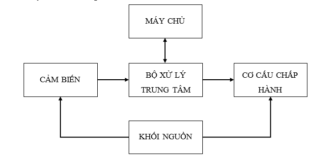
Figure: System block diagram
The server acts as both the user interface and the monitoring center. Here, the operator uses Simulink to input the desired three-dimensional trajectory (X, Y, Z) for the robot. Communication between the server and the system is done via a USB (UART) connection to the central controller.
Central processing unit: using an Arduino Mega 2560, it acts as the central coordinating and communication hub between the computer and the hardware. It receives the desired step data from the host computer and the actual rotation angle data from the sensor.
Sensors: implemented on an Arduino Nano, responsible for collecting feedback data from the robot mechanism. It uses an I2C multiplexer to communicate and sequentially read data from three AS5600 magnetic angle sensors mounted on each joint of the robot. The actual angle data collected is then sent back to the central controller via serial protocol to provide feedback to Simulink for the PID control loop.
The actuator consists of an Arduino Uno combined with a CNC Shield, acting as an intermediary layer between the controller and the motors. It receives control commands from the server via the central controller, then decodes and generates corresponding STEP/DIR pulse sequences. These signals are sent directly to three controllers to operate the motors.
Power Supply Block: The entire system is powered by a central 12V DC power supply, which provides power to all components. This 12V power supply is directly connected to the Arduino Uno and CNC Shield, where it powers the three drivers and the stepper motors. For boards requiring lower voltage, such as the Arduino Mega 2560 and Arduino Nano, and sensors, a step-down circuit is used to efficiently convert the voltage from 12V down to 5V.
2.2 Hardware design
2.2.1 Defining the workspace for the Delta robot.
The Delta robot's workspace is determined based on the selected geometric parameters by solving the inverse kinematics problem for the entire set of points within the surveyed area.
This process allows for the identification of the set of all possible positions of the end- effector that the mechanism can achieve, satisfying the constraints on joint limits and geometric conditions.
Table: Actual model parameters and parameters used in MATLAB Simulink simulation
The auxiliary parameters are calculated as follows:

Principles for defining workspace
The Delta robot consists of three identical active arms, connected from the base assembly to the mobile platform via ball joints, and passive arms.
The robot's workspace is defined as the set of all positions that the end-effector can move to, while also fulfilling the following conditions:
- A real, inverse kinematic solution exists for the given set of geometric parameters, ensuring the problem is geometrically feasible.
- The rotation angle of the active joints is within the mechanically permissible limits to ensure safety and prevent collisions during operation.
Dynamic coefficients inverse
For each leg i belongs to {1,2,3} , calculate:
Conditions for the existence of a solution
For each leg i :

The score (x,y,z) is valid if:

This theta i includes the following:

Calculation process
Define the initial survey area.
Given
, use inverse and forward kinematics to scan the coordinate points.
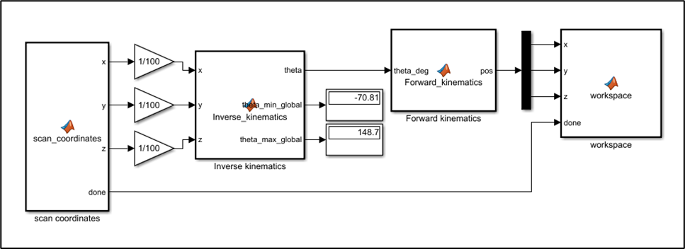
Figure: Program for defining the initial survey area
Each scan step

After surveying and gathering data, the working space for the Delta robot is found to be within the following range:

The angle theta i is with in the limits.

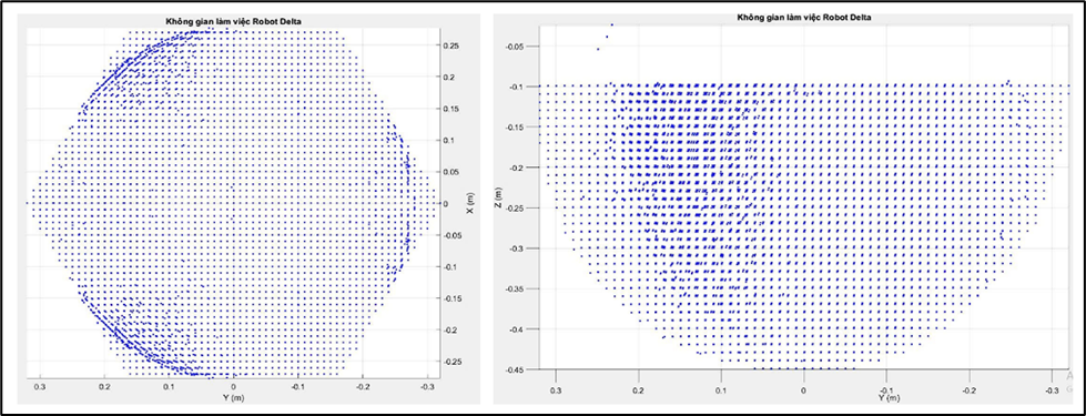
Figure: Delta robot 's workspace
Redefining the optimal workspace for the Delta robot .
Given

, after conducting the survey:
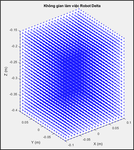
Figure: Optimal workspace for the Delta robot.
Conclusion: Within the surveyed area

, the angle theta i is with in the limits

All points meeting the feasibility conditions have joint angle values that fall entirely within the mechanically permissible limits. The results show that the actual working space of the Delta robot fully meets the design requirements and ensures stable and safe operation throughout the entire surveyed area.
2.2.2 Mechanical design of Delta robot components
Delta robot assembly video: https://youtube.com/shorts/m4SsIY5LkUw?feature=share
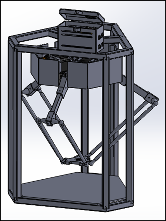
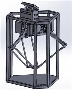
Figure : Delta robot model in Solidworks
D elta robot frame
The Delta robot frame is made from robust materials, ensuring excellent load-bearing capacity and high durability at a low cost. The frame is optimally designed to withstand heavy loads while maintaining stability and high performance.
Material: 20 x 20mm galvanized square pipe
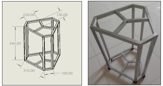
Figure: Delta robot frame
Fixed base plate
The Delta robot's base plate is the foundational component, serving as the main support frame for the entire robot system. This base plate is fixed to the Delta robot frame, allowing for flexible assembly and disassembly, while ensuring stability and precision during operation. Three actuators are mounted on the base plate, each controlling a crank connected to the robot's main arm.
Material: 5mm steel plate
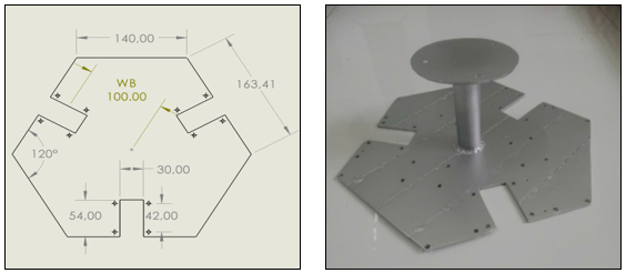
Figure : Fixed base plate
Mobile core
The movable base is the center point of the movable table (end). But The effector is the point where the parallel arms converge, responsible for transmitting motion from the robot frame to the manipulator. The movable base plays a crucial role in determining the precise position of the workpiece in 3D space, ensuring the stability and efficiency of the system's movements.
Material: 3D printing plastic
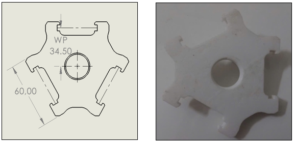
Figure : Movable base plate
Active arm
The active arm is a crucial component in the Delta Robot structure, directly connecting the stepper motor at the base to the parallel arms. This component is responsible for transmitting rotational motion from the motor into directed rotational motion, controlling the position and direction of the end-effector. With its rigid design and high precision, the active arm ensures operational efficiency and system stability.
Materials: 12x20mm square aluminum tubing, 3D printing plastic.
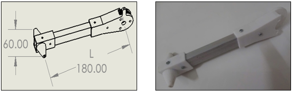
Figure : Active arm
Passive arm
The passive arm in a Delta robot is a component without its own motor; instead, it is controlled by the active arm via linkage mechanisms. The passive arm transmits motion from the active arm to the end-effector, helping to maintain the accuracy and stability of the system during operation. The structure of the passive arm is typically designed to minimize friction and ensure smooth movement throughout the robot's operation.
Material: 11.6mm diameter round aluminum tube
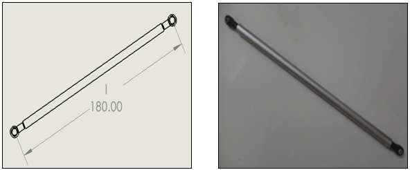
Figure :Passive arm
GT2 pulley and belt
The belt drive system utilizes GT2-20 and GT2-60 pulleys combined with a 220 mm long GT2 belt, acting as a reduction gear mechanism to increase torque transmitted to the drive joint. Thanks to the appropriate gear ratio, the system not only improves the lifting force and load capacity of the Delta robot but also enhances positional resolution, thereby increasing control accuracy and reducing vibration during operation.
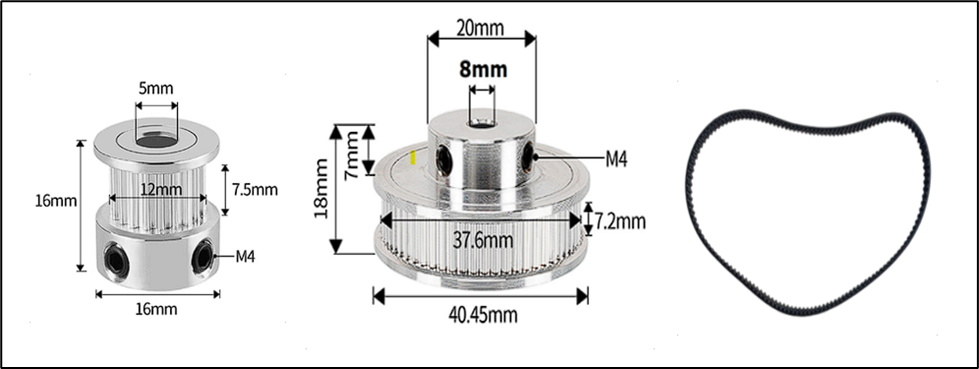
Figure : GT2 Pulley But 20, 60 and 220mm belts
Vertical shaft bearing support
Vertical shaft bearing housings are responsible for precisely fixing and orienting the drive shaft, ensuring stable rotation. Thanks to their ability to reduce friction and withstand heavy loads, the housings help the shaft rotate smoothly, minimizing vibration and wear.
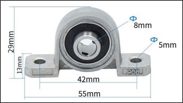
Figure : KP08 Vertical Shaft Bearing Support
2.3 Electrical and electronic design
2.3.1 Component selection and detailed analysis
Component selection was based on a balance between performance, cost, and compatibility within the Arduino and MATLAB/Simulink ecosystems. Each component was chosen to perform a specific function, contributing to the overall system performance.
Central processing unit: Arduino Mega 2560
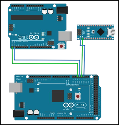
Figure: Arduino Mega 2560 connection diagram
Arduino Mega 2560: Acting as the command brain of the system, the Mega 2560, with its powerful ATmega2560 microcontroller, large memory, and numerous hardware interface ports, is the ideal platform for executing high-level tasks. The main functions of the Mega 2560 include:
- Execute the control algorithm: Run the C/C++ code automatically generated from the Simulink model, including the PID controller calculation blocks for all three axes.
- Data management: Receive actual angular position data from the feedback subsystem (Arduino Nano) and then send it to MATLAB/Simulink for processing.
- Decision-making and control: Based on the current error, accumulated error, and rate of change of the error, the PID controller calculates the output control signal and sends it to MATLAB/Simulink.
- Communication and Command: Send processed motion commands (based on PID output and inverse kinematics) to the actuator subsystem (Arduino Uno) to control the motor.
- Human-computer interface: Communicates with the computer via USB port to transmit data back to Simulink for real-time monitoring, analysis, and parameter adjustment.
Execution subsystem
This subsystem is responsible for converting numerical control commands into precise mechanical movements for the robot.
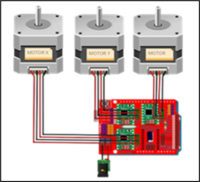
Figure: Arduino Uno connection diagram
Arduino Uno: Designated as a dedicated motion processor. Its sole task is to receive high-level motion commands from the Mega 2560 and convert them into highly precise STEP and DIR electronic pulse sequences. This includes controlling stepper motors, especially in microstepping and high-speed modes. Entrusting this task to a separate processor frees the Mega 2560 from the burden of intermittent, resource-intensive, and time-sensitive tasks.
Position feedback subsystem
This subsystem provides precise angular position data for each robot joint, forming a closed-loop feedback system for the PID controller.
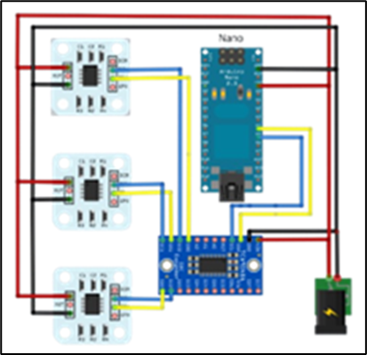
Figure: Arduino Nano connection diagram
Arduino Nano : Acts as a dedicated data acquisition unit. It is responsible for continuous communication with three AS5600 angular position sensors via the I2C bus. Managing an I2C bus with multiple devices, especially through a multiplexer, requires a series of sequential read and write commands. By letting the Nano handle this, the Mega 2560 can obtain position data for all three axes with a single request, instead of having to perform the entire complex I2C communication process itself . This ensures that the feedback data is always efficiently updated without interrupting critical control calculations taking place on the central processor.
2.3.2 Wiring and power supply diagram
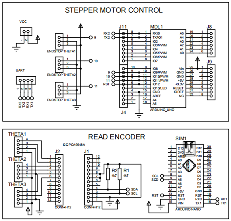
Figure: Detailed connection diagram
UART communication (Mega ⇔ Uno):
- The TX2 pin of the Mega 2560 (Pin 16) connects to the RX0 pin of the Uno (Pin 0).
- The RX2 pin of the Mega 2560 (Pin 17) connects to the TX0 pin of the Uno (Pin 1).
- Connect the common ground (GND) between the two boards.
I2C communication (Mega ⇔ Nano ⇔ Mux ⇔ Sensor ) :
- The TX1 pin of the Mega (Pin 18) connects to the RX0 pin of the Nano (Pin 0).
- The TX1 pin of the Mega (Pin 19) connects to the TX0 pin of the Nano (Pin 1).
- The A5/SCL pin of the Nano connects to the SCL pin of the PCA9548A multiplexer.
- The A4/SDA pin of the Nano connects to the SDA pin of the PCA9548A multiplexer.
- The SC0/SD0, SC1/SD1, and SC2/SD2 pin pairs of the PCA9548A are connected to the SCL/SDA pin pairs of the three AS5600 sensors, respectively.
- All devices on the I2C bus must be connected to a common ground (GND).
Connect the motor control unit (Uno ⇔ CNC Shield ⇔ A4988 ⇔ Motor):
- The CNC Shield plugs directly into the Arduino Uno.
- The A4988 modules are plugged into sockets X, Y, and Z on the shield.
- The STEP/DIR pins for the X, Y, and Z axes on the shield are connected to the Uno's digital pins according to the shield's diagram (for example: X - STEP/DIR is D2/D5, Y - STEP/DIR is D3/D6, Z - STEP/DIR is D4/D7).
- The outputs of the A4988 driver are connected to the four wires of each corresponding stepper motor.
Power supply diagram
Logic power (5V): The Arduino Mega 2560 is powered directly from the host PC's USB port. The 5V power supply for other logic boards such as the Uno and Nano, as well as sensors and multiplexers, is provided by the LM2596 step-down circuit.
Power supply (12V): An external, high-power power supply must be used to separately power the CNC Shield V3 via a DC jack or screw connector. This power supply provides the necessary energy for the stepper motors to operate. Separating the power supply and logic power supply helps prevent electromagnetic interference from the motor driver switching from affecting the operation of the microcontrollers, ensuring system stability.
2.4 Software design
2.4.1 Hardware communication between Arduino Uno, CNC Shield, and A4988 Driver
The system's foundation is an Arduino Uno, attached to a CNC Shield. A dedicated expansion board for CNC machine control applications. The CNC Shield provides slots for directly mounting A4988 stepper motor drivers.
The A4988 driver acts as an intermediary, receiving low-level logic signals from the Arduino (via the STEP, DIR, and ENABLE pins) and converting them into a current large enough to operate the stepper motor. The microstepping mode on the A4988 driver allows a full motor step to be divided into smaller steps (e.g., 1/2, 1/4, 1/8, or 1/16). This offers several advantages:
- Increased resolution: Robot movements become more precise.
- Smooth movement: Minimizes vibrations and noise during motor operation.
Conclusion : Choosing a 1/16 microstepping mode for the stepper motor driver ensures a balance between smooth movement, positioning accuracy, and system speed responsiveness. With this scaling ratio, the Delta robot achieves a smaller angular resolution, resulting in smoother head movement, reduced vibration, and improved trajectory quality, while maintaining sufficient torque to meet load and speed requirements during operation.
Engine initialization and configuration program
Each stepper motor (X, Y, Z) is initialized as a separate AccelStepper object, with STEP and DIR pins assigned. The common ENA pin for all three motors is connected to pin 8 on the Uno. Specifically, the AccelStepper objects are initialized with parameter 1 to specify the control mode (driver A4988), and the step and direction control pins are configured accordingly. The common enable pin is set for all drivers via setEnablePin(8). The setPinsInverted(false, false, true) function is used to configure the control pins inverted if needed, ensuring the correct rotation direction of the motor.
Setting the maximum speed setMaxSpeed(1000) and acceleration setAcceleration(3000) for the motor is extremely important. Stepper motors, especially when driven by constant current drivers like the A4988, can experience resonance or step loss if the speed changes too abruptly. Without acceleration or deceleration profiles, the motor can lose steps, leading to positional errors. Therefore, careful adjustment of these values is necessary to optimize performance and avoid step loss. This adjustment is also directly related to the ability of the PID controller in Simulink to achieve the desired coupling angles, as the underlying actuators must be able to reliably follow commands.
home_XYZ() function is used to return the robot's axes to their original home position. This process is accomplished by moving each axis in a specific direction until the corresponding limit switch is activated. The end_X, end_Y, and end_Z pins are configured as INPUT_PULLUP to read the limit switch status. During homing, speed and acceleration are set low to ensure safety and accuracy when approaching the endstop. After the limit switch is activated, the motor's current position is reset to 0 setCurrentPosition(0). Without a reliable home positioning process, the robot's sensed position can be inaccurate over time due to step loss. This inaccuracy will invalidate all subsequent kinematic calculations and PID control, resulting in significant position errors at the endpoint.
Command format received from Arduino Mega 2560
The system uses Serial Communication (UART) for the Arduino Uno to receive control commands from an Arduino Mega motherboard. Commands are sent as a structured text string, for example: X<steps>Y<steps>Z<steps>;.
- The characters X, Y, and Z identify the axis to be moved.
- <steps> is the corresponding number of steps.
- The semicolon ; is the character that terminates a command.
In the loop() function, the Arduino Uno continuously checks incoming data using Serial.available() and reads the entire command string using functions like Serial.read(). When a character is received, it is stored in the buffer variable . When a semicolon (;) is received, the string in the buffer is considered complete and terminated with a null character (\0). The strchr() function is used to find the position of the identifier characters X, Y, Z in the string. The atol() function then converts the numerical part after each identifier character into an integer value. These xVal, yVal, zVal values are then passed to the run() function to update the motor's target position.
2.4.2 I2C communication with AS5600 and PCA9548A sensors .
I2C multiplexer that allows multiple devices sharing the same I2C address to be connected to a single microcontroller. It operates by creating up to eight separate I2C buses (channels 0 to 7), and only one channel can be activated at a time. The default I2C address of the PCA9548A is 0x70. The `selectI2CChannel(uint8_t channel)` function is used to write a byte to the PCA9548A's control register, selecting the desired I2C channel by setting the channel bit in the byte to 1.
Reading sensor values: The readAS5600() function is responsible for communicating with the sensor. It sends a request to read the angle register (0x0C) and then requests two bytes of data. The 12-bit angle value is reconstructed by combining these two bytes (MSB << 8 | LSB).
Processing AS5600 sensor data
The AS5600 sensor provides 12-bit resolution angular data, equivalent to 4096 points in a 360-degree rotation (360/4096 = 0.08789 degrees). However, using this sensor for continuous rotation applications is problematic. The sensor only reports angles within the range of 0 to 360 degrees, and when the axis of rotation exceeds 360 degrees, the reading abruptly returns to 0. If this value is fed directly into a PID loop, the controller will receive a huge error (e.g., from 359 degrees to 0 degrees, the error is -359 degrees) and cause serious instability.
Angle data processing: In the sendAllAngles() function, the raw angle value from the sensor is compared with an initial angle value (initialAngle) recorded in the setup() function. The result is an angle deviation value (delta). The AS5600 sensor has a 12-bit resolution, corresponding to 4096 values (from 0 to 4095). When the rotation angle exceeds 360 degrees (from 4095 back to 0) or vice versa, simple subtraction will yield an incorrect result. The source code handles this by adding or subtracting 4096 if the delta value exceeds +/- 2048, ensuring the angle response value is always accurate. Finally, this delta value is converted to degrees and rounded to two decimal places.
Serial communication and synchronization: After processing, the angle data is sent via the Serial port as three floating-point numbers (floats), each 4 bytes, using the sendFloat() function. A crucial synchronization mechanism is implemented in the loop () loop; data is only sent to sendAllAnges() when the program receives a specific instruction byte, 0xA5, from Mega. This ensures that sensor readings and response data transmission are fully synchronized with the control loop on Simulink, avoiding unwanted or untimely data transmission.
3. Tests and results
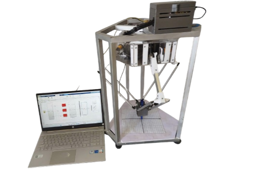
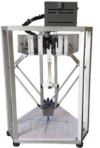
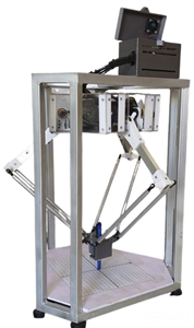
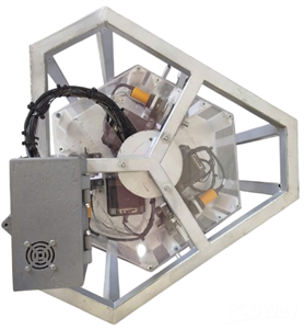
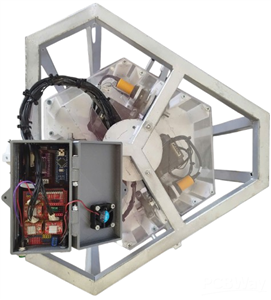
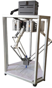
After a period of research and implementation, the authors' team successfully designed and manufactured the Delta Robot model, as shown in Figure below:
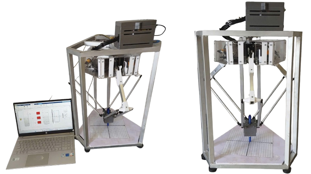
The system was built to meet the requirements for high positioning accuracy, stable trajectory tracking, fast movement speed, and operational reliability. Besides its practical significance in production, the model also serves as a useful learning and research tool. With the support of MATLAB/Simulink, learners can simulate and analyze the kinematics and dynamics of the Delta robot, and verify PID control algorithms in a virtual environment before experimental deployment. This not only helps minimize risks and save costs but also provides a visual and vivid understanding, contributing to improved teaching and training effectiveness, as well as the development of new research ideas in the field of industrial robotics.
3.1 Testing the control of a Delta robot without using a PID controller.
Testing the robot's position response when tracing a circular trajectory with a sampling rate T_s = 0.0 1s
This experiment investigates the robot's ability to track a path when drawing a circle centered at a radius of 5cm in the Z = -28cm plane.
This video illustrates the operation of a Delta robot without a PID controller:. https://youtube.com/shorts/gSkA82I4aIw
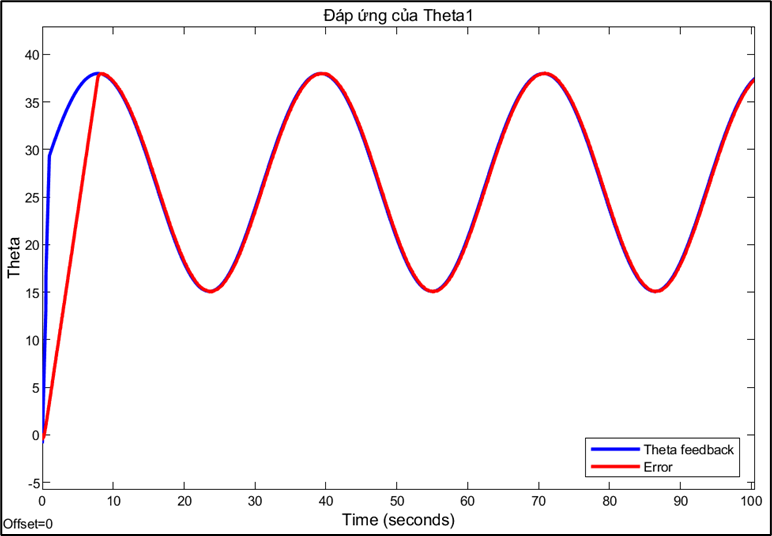
Response and error of joint 1:
Response and error of joint 2:
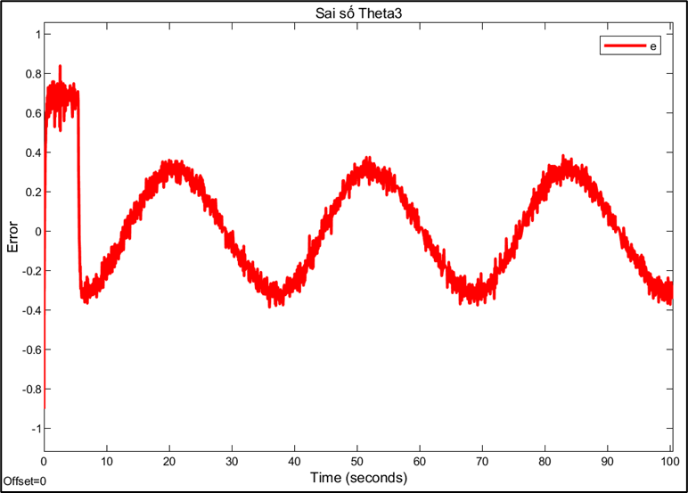
Response and error of joint 3:
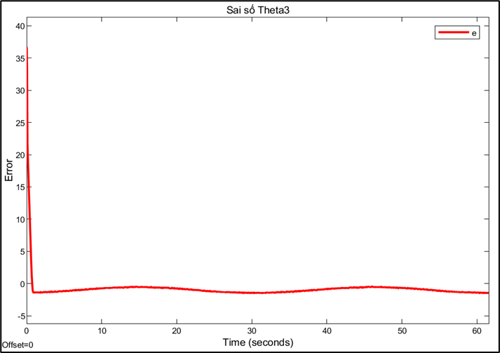
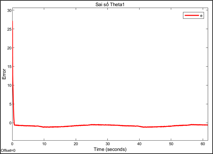
Observation: Experiments showed that the robot's joints stabilized relatively quickly; however, the steady-state error remained large due to the cumulative error during the conversion from angle to step size. The larger the step size, the more significant the accumulated error. Furthermore, during operation, step deviations or external influences may occur, but the system lacks the ability to self-correct to return to the correct position. These results suggest the need to add a PID controller to reduce errors, increase stability, and improve the accuracy of Delta robot control.
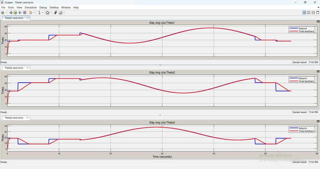
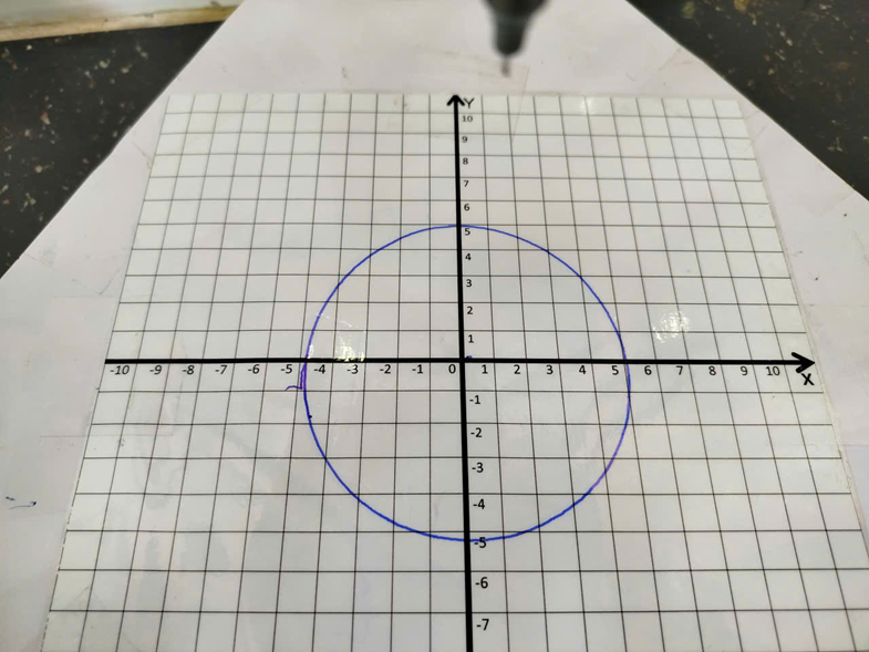
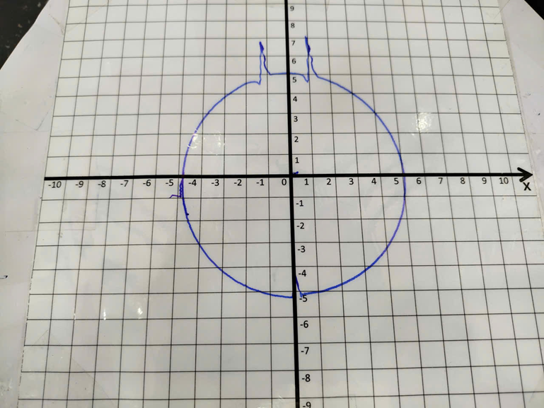
3.2 Experiment to draw a circular trajectory using a PID controller.
This experiment investigates the robot's ability to track a circle centered at a radius of 5cm in the Z-plane = -28cm. We will compare the trajectory quality with the sampling rate: 0.01s. For each sampling rate, a different set of PID parameters is fine-tuned to achieve the best performance.
Testing the robot's position response when tracing a circular trajectory with a sampling rate T_s = 0.01s.
PID parameters: Kp = 10, Ki = 200, Kd = 0.081
This video illustrates the operation of a Delta robot with a PID controller: https://youtube.com/shorts/XPRQhnA0KZo?feature=share
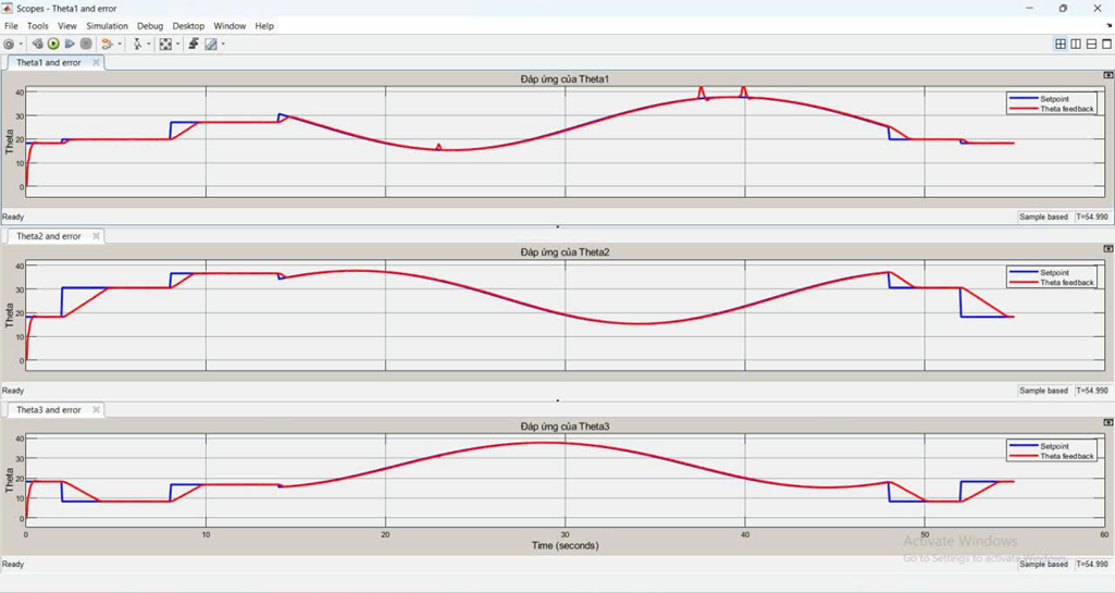
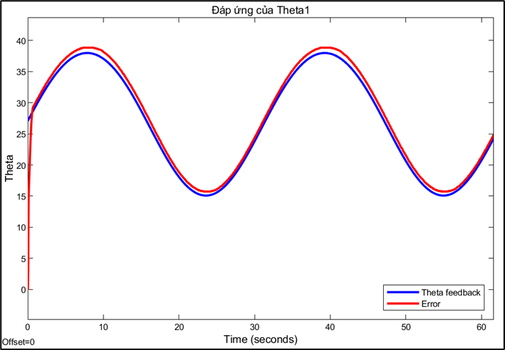
Response and error of joint 1:
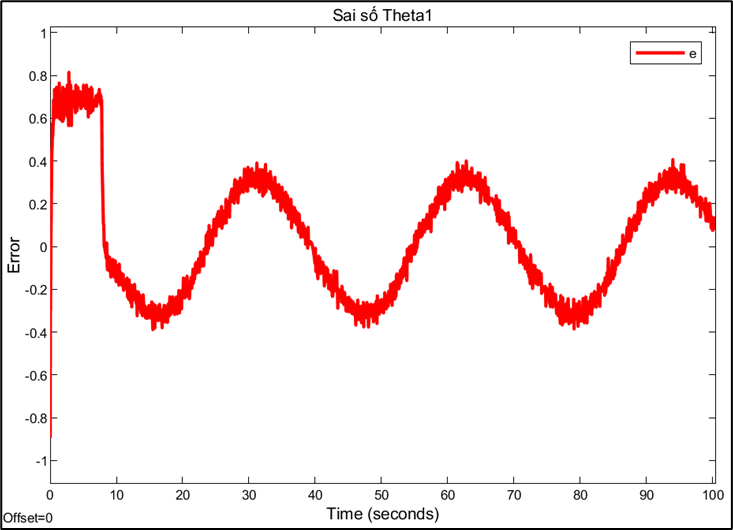
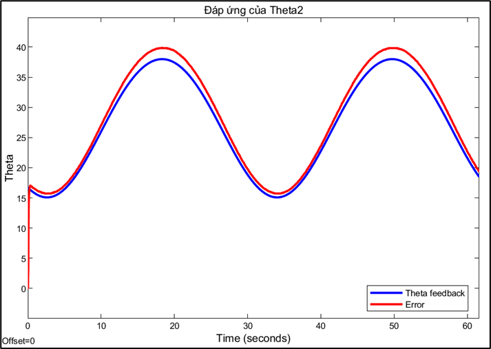
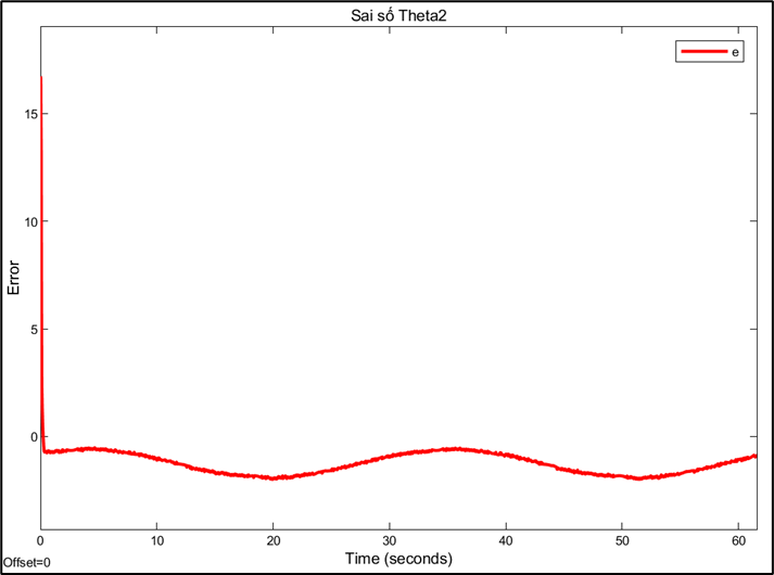
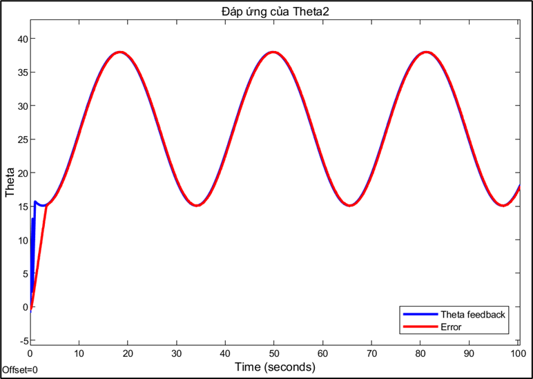
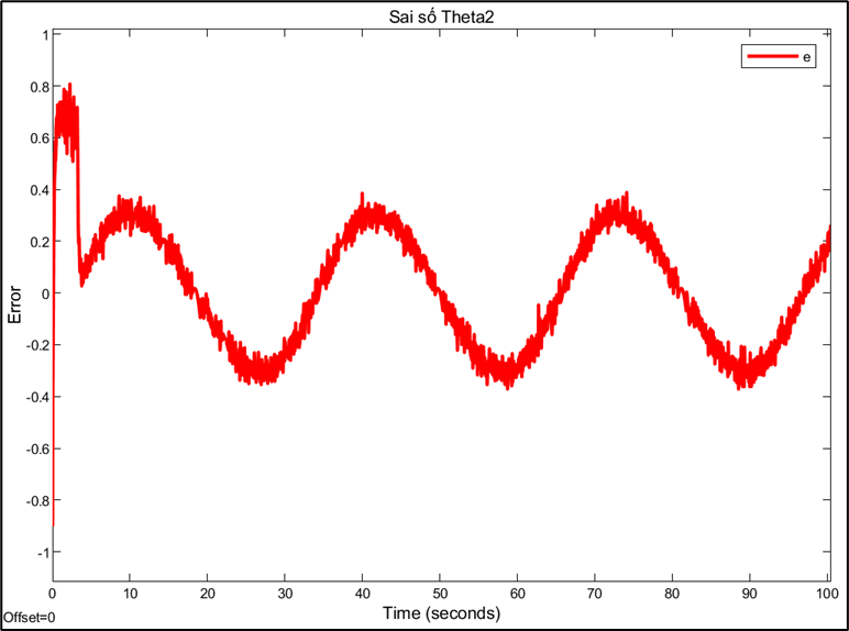
Response and error of joint 2:
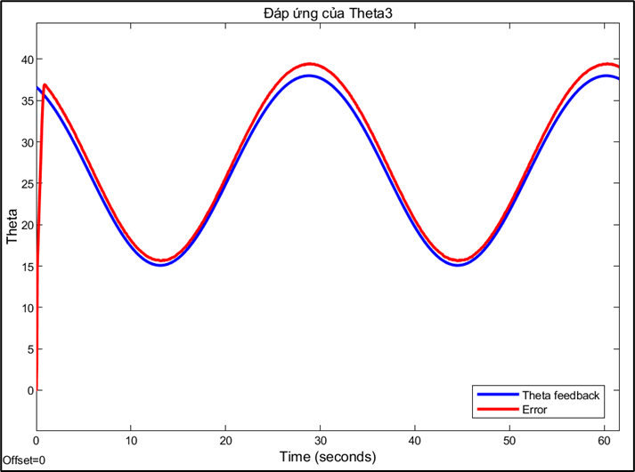
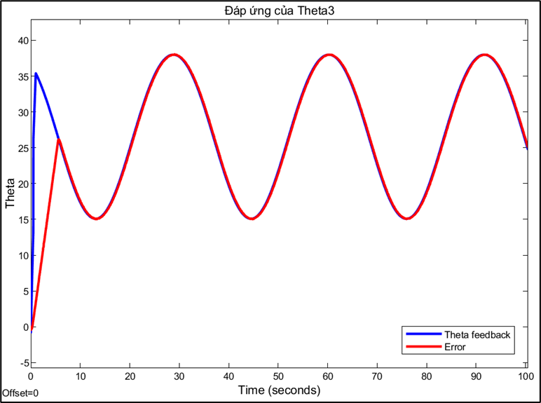
Response and error of joint 3:
Choosing the sampling rate is a technical decision based on trade-offs between conflicting factors. A high sampling rate (0.01s) allows for a fast system response and reduces errors, but may be limited by computation and data transmission speeds. Conversely, a sampling rate that is too low can cause instability or oscillations, while a rate that is too high can increase signal noise. This also explains why PID parameters need to be fine-tuned for each different sampling rate. A PID controller tuned to operate efficiently at a sampling rate of 0.01s will no longer be optimal when the rate is switched to 0.
Design of a Delta Robot Model combined with a PID Controller
*PCBWay community is a sharing platform. We are not responsible for any design issues and parameter issues (board thickness, surface finish, etc.) you choose.


Raspberry Pi 5 7 Inch Touch Screen IPS 1024x600 HD LCD HDMI-compatible Display for RPI 4B 3B+ OPI 5 AIDA64 PC Secondary Screen(Without Speaker)
BUY NOW


- Comments(0)
- Likes(1)
- 1 USER VOTES
- YOUR VOTE 0.00 0.00

-
10design
-
10usability
-
10creativity
-
10content
More by Khoi Ngo
-
Programmable Mist Maker - XIAO / QT PY Extension
273 0 0 -
RadioHAT - Raspberry Pi radio development platform
275 0 1 -
-
-
-
-
ARPS-2 – Arduino-Compatible Robot Project Shield for Arduino UNO
2834 0 6 -
A Compact Charging Breakout Board For Waveshare ESP32-C3
3337 3 8 -
AI-driven LoRa & LLM-enabled Kiosk & Food Delivery System
3638 2 2


