|
Arduino Opla IoT kitArduino
|
x 1 |

|
arduino IDEArduino
|
Arduino OPLA IoT Kit blink_ Example and Symon Says Game
The Arduino Opla IoT Kit is a versatile kit designed for creating and managing Internet of Things projects. The "Opla" stands for "Open-source Programmable Logic Analyzer," but in the context of the IoT Kit, it represents a set of tools and components to help you develop connected applications.

This kit provides a robust set of components for creating a wide range of IoT applications, from simple sensor projects to more complex systems involving cloud connectivity and data analysis.
First, let's see what components this kit contains:
- MKR IoT Carrier with a place for a 3.7V lithium battery
- Arduino MKR WiFi 1010 board
- Plastic box for carrier
- moisture sensor
- PIR sensor
- and various cables that are needed to connect external components, as well as a USB cable for connecting to a PC

- MKR IoT Carrier board contains several sensors for:
- Temperature and humidity
- Pressure sensor
- Light sensor
- 5 capacitive buttons
- than 2 relays
- micro SD card reader
- different types of connectors
- and on the front side, color display.
On the arduino page dedicated specifically to this kit you will find a detailed description, pictures and assembly instructions as well as many projects that can be made with the given components.
Тhis is my first time meeting with this kit, so I will present you a very simple project, actually a famous game called "Simon says" for which this module fully corresponds physically, considering the central round display, touch sensitive buttons , RGB LEDs, as well as audio support.
To make this project we need only MKR IoT Carrier and Arduino MKR WiFi 1010 board. Since this is the first project with this kit I will explain the assembly of the device step by step. First, we mount the microcontroller board on the appropriate base, making sure that the markings on the board and the base match.

If you want to power the board and carrier with a battery, you will need one Li-Ion 3.7V battery, while paying attention to the polarity. Тo make project more portable and compact, you can place the MKR IoT Carrier in the plastic casing. This provides good protection for the hardware and makes it easier to attach it to surfaces (for example, a wall), while also providing a nice glow for the RGB LEDs. Now the device is assembled and we can move on to the software part.
First we need to download the Arduino IDE software from the () given address. I am specifically using the current latest version 2.3.2.

You can also use the Arduino Web Editor (requires an account), which is directly connected to Arduino IoT Cloud, but more about that on another occasion. Then we connect the module to the USB port of the computer and the arduino IDE editor will show options for updating the libraries and boards, where we need to install them. I have already performed this operation before. Next we select the appropriate COM port and we are ready to install the first code. And now, logically, to make sure that everything is connected and installed correctly, we will upload a very simple Blink sketch.

The onboard LED of the Arduino MKR WiFi 1010 is connected to pin13, and a small relay is also connected to the same pin, so that both visually and acoustically we will be able to make sure of the functionality of the device. Now we can finally upload the previously mentioned sketch for Simon Says game. Let me not forget to mention that the original sketch is the work of Julián Caro Linares and all credit goes to him. We paste the code in Arduino IDE and press compile. If we get error we need to install "Arduino_MKRIoTCarrier" library.

In Sketch - include library - manage libraries - search for desired library and install. Now we can compile code without error. Next is uploading the code to the Arduino board. Now the game is ready for testing and we will see how it behaves in real conditions. At start we need to chuse between three difficulty levels: Easy, Normal, and Hard.

The rules of the game are known and the goal is to guess as many sequences as possible.
And finally a short conclusion. Alough this Arduino Kit is primarly intended for IoT projects, this time I presented two simple local projects to introduce you to the basic finctions, and some of the possibilities and in one of the next videos an IoT project will follow.
/*
  Blink

  Turns an LED on for one second, then off for one second, repeatedly.

  Most Arduinos have an on-board LED you can control. On the UNO, MEGA and ZERO
  it is attached to digital pin 13, on MKR1000 on pin 6. LED_BUILTIN is set to
  the correct LED pin independent of which board is used.
  If you want to know what pin the on-board LED is connected to on your Arduino
  model, check the Technical Specs of your board at:
  https://www.arduino.cc/en/Main/Products

  modified 8 May 2014
  by Scott Fitzgerald
  modified 2 Sep 2016
  by Arturo Guadalupi
  modified 8 Sep 2016
  by Colby Newman

  This example code is in the public domain.

  https://www.arduino.cc/en/Tutorial/BuiltInExamples/Blink
*/

// the setup function runs once when you press reset or power the board
void setup() {
  // initialize digital pin LED_BUILTIN as an output.
  pinMode(13, OUTPUT);
}

// the loop function runs over and over again forever
void loop() {
  digitalWrite(13, HIGH); // turn the LED on (HIGH is the voltage level)
  Serial.println("Led On");
  delay(1000);                      // wait for a second
  digitalWrite(13, LOW);   // turn the LED off by making the voltage LOW
  Serial.println("Led Off");
  delay(1000);                      // wait for a second
}
/*
  Opla Simon Says

  Created by Julián Caro Linares

  CC-BY-SA
*/

// Libraries
#include <Arduino_MKRIoTCarrier.h>


// Definitions

#define DEBUG true// Uncomment to see the Serial port debug messages

#define SIMON_BLUE 0
#define SIMON_RED 1
#define SIMON_GREEN 3
#define SIMON_YELLOW 4

#define TOUCH_BLUE TOUCH0
#define TOUCH_RED TOUCH1
#define TOUCH_GREEN TOUCH3
#define TOUCH_YELLOW TOUCH4

#define BLUE_TONE 330    // MI
#define RED_TONE 262     // DO
#define GREEN_TONE 440   // LA
#define YELLOW_TONE 294  // SI
#define GAMEOVER_TONE 100

// Global variables
int difficulty = 1;// Between 1-3 where 1 is the easiest and 3 the hardest
int sequence[30]; // 0-BLUE,1-RED,2-GREEN,3-YELLOW
//int sequence[10] = {0,1,2,3,0,1,2,3,0,1}; // 0-BLUE,1-RED,2-GREEN,3-YELLOW --TEST SEQUENCE
int turn = 0;
int delay_time = 500; // Milliseconds
bool wait_press = false;
bool wrong_button = false;
bool difficulty_press =false;


// Objects initialization
MKRIoTCarrier carrier;
uint32_t gameover_color = carrier.leds.Color(0, 255, 0);


// Functions declaration
void color_animation(char color); // Where b-blue, r-red, g-green, y-yellow
void gameover();
void difficulty_selector();
void new_sequence();


void setup() {

  // Opla setup
  CARRIER_CASE = true;
  carrier.begin();

#ifdef DEBUG
  // Initialize serial and wait for port to open:
  Serial.begin(9600);
  // This delay gives the chance to wait for a Serial Monitor without blocking if none is found
  delay(1500);
#endif

  // Random seed
  while (!carrier.Light.colorAvailable()) {
    delay(5);
  }
  int none;
  int light;
  carrier.Light.readColor(none, none, none, light);
  randomSeed(light); // TODO create a good seed


  // Difficulty selector
  difficulty_selector();

  // Sequence generator
  new_sequence();

  // LEDS Initialization
  carrier.leds.setBrightness(10);
  carrier.leds.setPixelColor(SIMON_BLUE, 0, 0, 255);   // BLUE button GRB notation
  carrier.leds.setPixelColor(SIMON_RED, 0, 255, 0);   // RED button GRB notation
  carrier.leds.setPixelColor(SIMON_GREEN, 255, 0, 0);   // GREEN button GRB notation
  carrier.leds.setPixelColor(SIMON_YELLOW, 255, 255, 0); // YELLOW button GRB notation
  carrier.leds.show();


  // Delay before starting the game
  delay(3000);
}

void loop() {

  // Begin of the game
  carrier.leds.clear();
  carrier.leds.show();
  carrier.display.fillScreen(ST77XX_BLACK);
  carrier.display.setCursor(35, 100);
  carrier.display.print("BEGIN");
  wrong_button = false;
  delay(5000);

  // Turn loop
  for (int turn = 1; turn <= difficulty * 10; turn ++) {

    if (wrong_button == true){
      #ifdef DEBUG
        Serial.println("EXIT TURN LOOP");
      #endif
      break;
    }

    #ifdef DEBUG
        Serial.print("\nTurn: ");
        Serial.println(turn);
    #endif

    // Prepare turn
    if (turn < 10) {
      carrier.display.setCursor(95, 85);
    }
    else {
      carrier.display.setCursor(65, 85);
    }
    carrier.display.fillScreen(ST77XX_BLACK);
    carrier.display.setTextSize(10);
    carrier.display.print(turn);

    // Machine turn
    for (int j = 0; j < turn; j++) {

      #ifdef DEBUG
        Serial.print("Mach index: ");
        Serial.println(j);

        Serial.print("Value: ");
        Serial.println(sequence[j]);
      #endif

      carrier.leds.clear();
      carrier.leds.show();

      switch (sequence[j]) {
        case 0: // BLUE
          color_animation('b');
          break;
        case 1: // RED
          color_animation('r');
          break;
        case 2: // GREEN
          color_animation('g');
          break;
        case 3: // YELLOW
          color_animation('y');
          break;
        default:
          #ifdef DEBUG
            Serial.println("ERROR: Wrong sequence value");
            Serial.println(sequence[j]);
          #endif
          break;
      }


    }

    // Player turn
    for (int k = 0; k < turn; k++) {

      if (wrong_button == true){
        #ifdef DEBUG
          Serial.println("EXIT PLAYER LOOP");
        #endif
        break;
      }

      #ifdef DEBUG
        Serial.println("PLAYER TURN INDEX");
        Serial.println(k);
        Serial.println("SEQUENCE VALUE: ");
        Serial.println(sequence[k]);
      #endif

      wait_press = false;

      switch (sequence[k]) {

        case 0: // BLUE

          #ifdef DEBUG
            Serial.println("BLUE CASE");
            Serial.print("PLAYER: ");
            Serial.println(sequence[k]);
          #endif

          while (wait_press == false) {
            carrier.Buttons.update();

            if (carrier.Buttons.onTouchDown(TOUCH_BLUE)){
              #ifdef DEBUG
                Serial.println("SUCCESS BLUE");
              #endif
              delay(200);
              color_animation('b');

              wait_press = true;
              continue;
            }
            else if (carrier.Buttons.onTouchDown(TOUCH_RED) || carrier.Buttons.onTouchDown(TOUCH_GREEN) || carrier.Buttons.onTouchDown(TOUCH_YELLOW)){
              #ifdef DEBUG
                Serial.println("BLUE-WRONG BUTTON");
              #endif
              delay(200);
              wait_press = true;
              wrong_button = true;
              gameover();
              break;
            }
          }

          break;
        case 1: // RED

          #ifdef DEBUG
            Serial.println("RED CASE");
          #endif

          while (wait_press == false) {
            carrier.Buttons.update();

            if (carrier.Buttons.onTouchDown(TOUCH_RED)){
              #ifdef DEBUG
                Serial.println("SUCCESS RED");
              #endif
              delay(200);
              color_animation('r');

              wait_press = true;
              continue;
            }
            else if (carrier.Buttons.onTouchDown(TOUCH_BLUE) || carrier.Buttons.onTouchDown(TOUCH_GREEN) || carrier.Buttons.onTouchDown(TOUCH_YELLOW)){
              #ifdef DEBUG
                Serial.println("RED-WRONG BUTTON");
              #endif
              delay(200);
              wait_press = true;
              wrong_button = true;
              gameover();
              break;
            }
          }

          break;
        case 2: // GREEN

          #ifdef DEBUG
            Serial.println("GREEN CASE");
          #endif

          while (wait_press == false) {
            carrier.Buttons.update();

            if (carrier.Buttons.onTouchDown(TOUCH_GREEN)){
              #ifdef DEBUG
                Serial.println("SUCCESS GREEN");
              #endif
              delay(200);
              color_animation('g');

              wait_press = true;
              continue;
            }
            else if (carrier.Buttons.onTouchDown(TOUCH_RED) || carrier.Buttons.onTouchDown(TOUCH_BLUE) || carrier.Buttons.onTouchDown(TOUCH_YELLOW)){
              #ifdef DEBUG
                Serial.println("GREEN-WRONG BUTTON");
              #endif
              delay(200);
              wait_press = true;
              wrong_button = true;
              gameover();
              break;
            }
          }

          break;

        case 3: // YELLOW

          #ifdef DEBUG
            Serial.println("YELLOW CASE");
          #endif

          while (wait_press == false) {
            carrier.Buttons.update();

            if (carrier.Buttons.onTouchDown(TOUCH_YELLOW)){
              #ifdef DEBUG
                Serial.println("SUCCESS YELLOW");
              #endif
              delay(200);
              color_animation('y');

              wait_press = true;
              continue;
            }
            else if (carrier.Buttons.onTouchDown(TOUCH_RED) || carrier.Buttons.onTouchDown(TOUCH_GREEN) || carrier.Buttons.onTouchDown(TOUCH_BLUE)){
              #ifdef DEBUG
                Serial.println("YELLOW-WRONG BUTTON");
              #endif
              delay(200);
              wait_press = true;
              wrong_button = true;
              gameover();
              break;
            }
          }

          break;
      }

    }
  }

  // End catch
  carrier.leds.clear();
  carrier.leds.setPixelColor(2, 255, 0, 0);
  carrier.leds.show();
  carrier.display.fillScreen(ST77XX_BLACK);
  carrier.display.setTextSize(6);
  carrier.display.setCursor(70, 100);
  carrier.display.print("END");

  while (true) {
    carrier.Buttons.update();

    if (carrier.Buttons.onTouchUp(TOUCH2)) {
      carrier.Buzzer.sound(750);
      delay(250);
      carrier.Buzzer.noSound();
      carrier.display.fillScreen(ST77XX_BLACK);
      carrier.display.setTextSize(6);
      carrier.display.setCursor(70, 100);
      carrier.display.print("NEW");
      delay(3000);
      break;
    }
    delay(500);
  }

  // New game sequence
  difficulty_selector();
  new_sequence();
  delay(2000); // Time to see the difficulty selected


}


void difficulty_selector(){

  carrier.leds.setBrightness(10);
  carrier.leds.setPixelColor(1, 255, 0, 0);   // EASY
  carrier.leds.setPixelColor(2, 0, 0, 255);   // NORMAL
  carrier.leds.setPixelColor(3, 0, 255, 0);   // HARD
  carrier.leds.show();
  carrier.display.setRotation(0);
  carrier.display.setTextSize(3);
  carrier.display.fillScreen(ST77XX_BLACK);
  carrier.display.setCursor(35, 110);
  carrier.display.print("DIFFICULTY");

  difficulty_press = false;
  while (difficulty_press == false) {
    carrier.Buttons.update();
    if (carrier.Buttons.onTouchDown(TOUCH1)){
      difficulty = 1;
      difficulty_press = true;
    }
    else if (carrier.Buttons.onTouchDown(TOUCH2)){
      difficulty = 2;
      difficulty_press = true;
    }
    else if (carrier.Buttons.onTouchDown(TOUCH3)){
      difficulty = 3;
      difficulty_press = true;
    }
    delay(100);
  }
}

void new_sequence(){

  carrier.display.fillScreen(ST77XX_BLACK);
  carrier.display.setRotation(0);
  carrier.display.setTextSize(6);

  switch (difficulty) {
    default:
    //Like case 1
    case 1:
      carrier.display.setCursor(55, 100);
      carrier.display.print("EASY");

      for (int i = 0; i < 10; i++) {
        sequence[i] = random(0, 4);
        #ifdef DEBUG
                Serial.print("Sequence:");
                Serial.println(i);
                Serial.println(sequence[i]);
        #endif
      }
      break;
    case 2:
      carrier.display.setCursor(17, 100);
      carrier.display.print("NORMAL");

      for (int i = 0; i < 20; i++) {
        sequence[i] = random(0, 4);
        #ifdef DEBUG
                Serial.print("Sequence:");
                Serial.println(i);
                Serial.println(sequence[i]);
        #endif
      }
      break;
    case 3:
      carrier.display.setCursor(50, 100);
      carrier.display.print("HARD");

      for (int i = 0; i < 30; i++) {
        sequence[i] = random(0, 4);
        #ifdef DEBUG
                Serial.print("Sequence:");
                Serial.println(i);
                Serial.println(sequence[i]);
        #endif
      }
      break;
  }
}

void color_animation(char color){

  switch (color){

    case 'b':
      // ON
      carrier.leds.setPixelColor(SIMON_BLUE, 0, 0, 255);
      carrier.leds.show();
      //carrier.display.fillScreen(ST77XX_BLUE);
      carrier.Buzzer.sound(BLUE_TONE);
      delay(delay_time);

      // OFF
      carrier.Buzzer.noSound();
      carrier.leds.clear();
      carrier.leds.show();
      //carrier.display.fillScreen(ST77XX_BLACK);
      delay(delay_time);

      break;

    case 'r':
      // ON
      carrier.leds.setPixelColor(SIMON_RED, 0, 255, 0);
      carrier.leds.show();
      //carrier.display.fillScreen(ST77XX_RED);
      carrier.Buzzer.sound(RED_TONE);
      delay(delay_time);

      // OFF
      carrier.Buzzer.noSound();
      carrier.leds.clear();
      carrier.leds.show();
      //carrier.display.fillScreen(ST77XX_BLACK);
      delay(delay_time);

      break;

    case 'g':
      // ON
      carrier.leds.setPixelColor(SIMON_GREEN, 255, 0, 0);
      carrier.leds.show();
      //carrier.display.fillScreen(ST77XX_GREEN);
      carrier.Buzzer.sound(GREEN_TONE);
      delay(delay_time);

      // OFF
      carrier.Buzzer.noSound();
      carrier.leds.clear();
      carrier.leds.show();
      //carrier.display.fillScreen(ST77XX_BLACK);
      delay(delay_time);

      break;

    case 'y':
      // ON
      carrier.leds.setPixelColor(SIMON_YELLOW, 255, 255, 0);
      carrier.leds.show();
      //carrier.display.fillScreen(ST77XX_YELLOW);
      carrier.Buzzer.sound(YELLOW_TONE);
      delay(delay_time);

      // OFF
      carrier.Buzzer.noSound();
      carrier.leds.clear();
      carrier.leds.show();
      //carrier.display.fillScreen(ST77XX_BLACK);
      delay(delay_time);

      break;

  }
}

void gameover(){

  #ifdef DEBUG
    Serial.println("GAMEOVER");
  #endif
  // ON
  carrier.leds.fill(gameover_color, 0, 5);
  carrier.leds.show();
  carrier.Buzzer.sound(GAMEOVER_TONE);
  carrier.display.fillScreen(ST77XX_RED);
  carrier.display.setTextSize(4);
  carrier.display.setCursor(25, 105);
  carrier.display.print("GAMEOVER");

  delay(2000);

  // OFF
  carrier.Buzzer.noSound();
  //carrier.display.fillScreen(ST77XX_BLACK);
  delay(5000);
}
Arduino OPLA IoT Kit blink_ Example and Symon Says Game









Raspberry Pi 5 7 Inch Touch Screen IPS 1024x600 HD LCD HDMI-compatible Display for RPI 4B 3B+ OPI 5 AIDA64 PC Secondary Screen(Without Speaker)
BUY NOW


- Comments(0)
- Likes(0)
More by Mirko Pavleski
-
 Arduino 3D Printed self Balancing Cube
Self-balancing devices are electronic devices that use sensors and motors to keep themselves balanc...
Arduino 3D Printed self Balancing Cube
Self-balancing devices are electronic devices that use sensors and motors to keep themselves balanc...
-
 DIY ESP32 Universal Timer with Touchscreen & Rotary Encoder
In several of my previous videos, I presented different projects based on the CrowPanel 2.1-inch HM...
DIY ESP32 Universal Timer with Touchscreen & Rotary Encoder
In several of my previous videos, I presented different projects based on the CrowPanel 2.1-inch HM...
-
 Build a Real 5-Band Parametric EQ with ESP32 + WM8960 - Stereo DSP Audio Processor
Audio equalizer (EQ) is an electronic device that allows control over the strength of different fre...
Build a Real 5-Band Parametric EQ with ESP32 + WM8960 - Stereo DSP Audio Processor
Audio equalizer (EQ) is an electronic device that allows control over the strength of different fre...
-
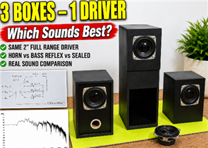 Bass Reflex vs Sealed vs Horn – Same 2 inch Speaker Test
In one of the previous videos I presented the making of a miniature Horn type speaker box with a 2 ...
Bass Reflex vs Sealed vs Horn – Same 2 inch Speaker Test
In one of the previous videos I presented the making of a miniature Horn type speaker box with a 2 ...
-
 Building a Mini Fostex Horn Speaker with a 2-Inch Full-Range Driver
A back-loaded horn speaker is a loudspeaker design that channels the rear sound wave of a driver th...
Building a Mini Fostex Horn Speaker with a 2-Inch Full-Range Driver
A back-loaded horn speaker is a loudspeaker design that channels the rear sound wave of a driver th...
-
 ESP32 Moon Lamp That Shows the Real Moon Phase on Crowpanel Round Dispaly
Recently on the Hackaday portal I came across a very interesting project called Moon Display by aut...
ESP32 Moon Lamp That Shows the Real Moon Phase on Crowpanel Round Dispaly
Recently on the Hackaday portal I came across a very interesting project called Moon Display by aut...
-
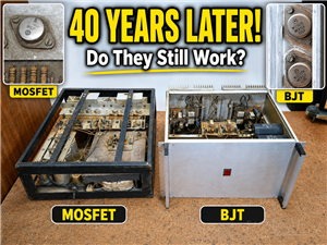 40-Year-Old DIY Power Amplifiers – Do They Still Work - 500W MOSFET & Transistor Amps
This time I want to describe my two DIY super powerful audio amplifiers that I made about 40 years ...
40-Year-Old DIY Power Amplifiers – Do They Still Work - 500W MOSFET & Transistor Amps
This time I want to describe my two DIY super powerful audio amplifiers that I made about 40 years ...
-
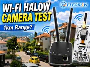 Wi-Fi HaLow Explained! Long-Range Camera Test up to 300m (ESP32 + ThinkNode G4 from ELECROW)
I recently needed to install a security camera at a relatively large distance from my home, more pre...
Wi-Fi HaLow Explained! Long-Range Camera Test up to 300m (ESP32 + ThinkNode G4 from ELECROW)
I recently needed to install a security camera at a relatively large distance from my home, more pre...
-
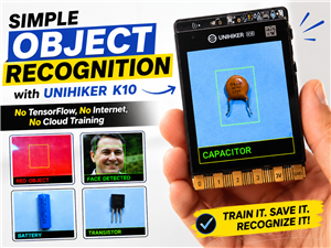 Simple Object Recognition with the UNIHIKER K10 – No TensorFlow, No Internet, No Cloud AI
Object recognition has become one of the most popular applications of artificial intelligence and em...
Simple Object Recognition with the UNIHIKER K10 – No TensorFlow, No Internet, No Cloud AI
Object recognition has become one of the most popular applications of artificial intelligence and em...
-
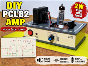 DIY PCL82 Tube Amplifier, Single-Ended Amp with Amazing Sound
The idea for this project came from a local electronics magazine called EMITER, issue 12/13 from 20...
DIY PCL82 Tube Amplifier, Single-Ended Amp with Amazing Sound
The idea for this project came from a local electronics magazine called EMITER, issue 12/13 from 20...
-
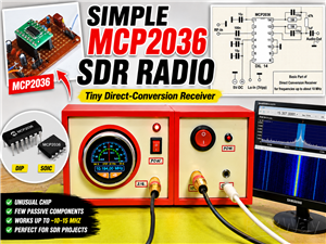 Simple MCP2036 SDR Radio - The Most Unusual Software Defined Radio
SDR (Software Defined Radio) is a radio communication system where many of the key electronic compo...
Simple MCP2036 SDR Radio - The Most Unusual Software Defined Radio
SDR (Software Defined Radio) is a radio communication system where many of the key electronic compo...
-
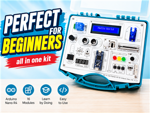 Elecrow All-in-One Arduino Starter Kit Review - 20 Projects & 16 Modules
This time I will describe a simple and practical way to enter the world of microcontrollers, specif...
Elecrow All-in-One Arduino Starter Kit Review - 20 Projects & 16 Modules
This time I will describe a simple and practical way to enter the world of microcontrollers, specif...
-
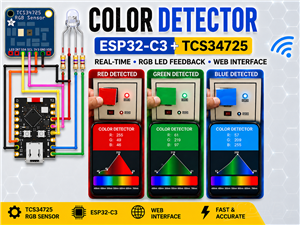 ESP32-C3 Color Detector with TCS34725, Real-Time RGB Detection & Web Interface
Color detection is a fundamental task in many embedded systems – from industrial sorting machines t...
ESP32-C3 Color Detector with TCS34725, Real-Time RGB Detection & Web Interface
Color detection is a fundamental task in many embedded systems – from industrial sorting machines t...
-
 DIY ESP32 Telegram Flood Protection System - Smart Home Automation
Recently I had an unpleasant experience in my home, specifically my ground floor was flooded as a r...
DIY ESP32 Telegram Flood Protection System - Smart Home Automation
Recently I had an unpleasant experience in my home, specifically my ground floor was flooded as a r...
-
 Real-Time Air Traffic Radar using ESP32 + ADS-B Data
ADS-B, which stands for Automatic Dependent Surveillance-Broadcast, is the modern standard for trac...
Real-Time Air Traffic Radar using ESP32 + ADS-B Data
ADS-B, which stands for Automatic Dependent Surveillance-Broadcast, is the modern standard for trac...
-
 DIY Green Laser Night Sky Object Finder - Find Stars & Galaxies Instantly with great accuracy
As an amateur astronomer, especially at the beginning, the most difficult part of observing the nig...
DIY Green Laser Night Sky Object Finder - Find Stars & Galaxies Instantly with great accuracy
As an amateur astronomer, especially at the beginning, the most difficult part of observing the nig...
-
 DIY Avionics Simulator with ESP32 - Artificial Horizon, Compass & Altimeter
The inspiration for this project comes from classical aircraft cockpit instruments used for navigat...
DIY Avionics Simulator with ESP32 - Artificial Horizon, Compass & Altimeter
The inspiration for this project comes from classical aircraft cockpit instruments used for navigat...
-
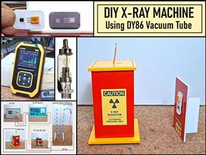 DIY Miniature X-Ray Machine using a TV Vacuum Tube DY86
An X-ray machine (or radiograph) is a quick, painless medical test that produces images of the struc...
DIY Miniature X-Ray Machine using a TV Vacuum Tube DY86
An X-ray machine (or radiograph) is a quick, painless medical test that produces images of the struc...
-
Émetteur Récepteur Optique Expérimental (communication UART ATtiny + fibre optique)
150 0 1 -
SmallOLED - Live PC Stats, Animated Clocks & Audio Visualizer
1000 0 3 -
"Talking Multimeter": Arduino-Based Speech Add-on for Multimeters with SCPI Protocol
574 0 1 -
Programmable Mist Maker - XIAO / QT PY Extension
3044 2 3 -
RadioHAT - Raspberry Pi radio development platform
2590 0 4 -
-
-