


|
fusion360 |
|

|
arduino IDEArduino
|
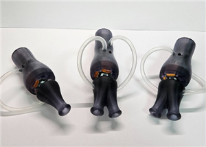
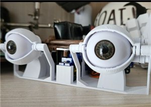
Animatronic Eyes
1. What is this project?
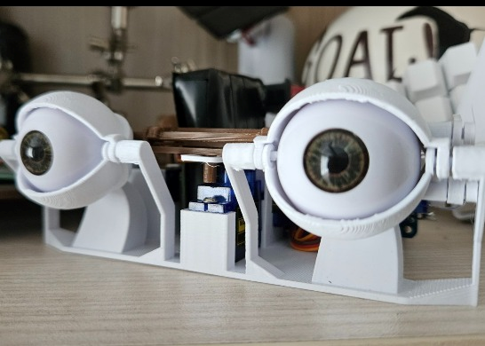
This is a robotics project I developed for one of my classes. It is a fully functional set of animatronic eyes capable of looking in all directions (X/Y axis) and blinking/winking (independent eyelids).
The system is powered by an ESP32, which connects via Bluetooth to a standard PS4 controller. This allows for real-time manual control of the eyes using the analog sticks and triggers, rather than just running pre-programmed loops.
2. Why did I make it?
I built this to learn more about servo kinematics and Bluetooth integration. I wanted to move away from simple automated movements and create something interactive. Using a game controller makes the mechanism feel much more like a digital puppet.
The goal was to make this accessible and affordable, so it uses standard, low-cost components that most students or hobbyists already have lying around, rather than expensive proprietary robotics gear. Also i had only 5 servos lying around so i couldn't copy any of the existing designs. ;D
3. How does it work?
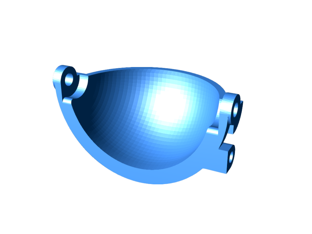
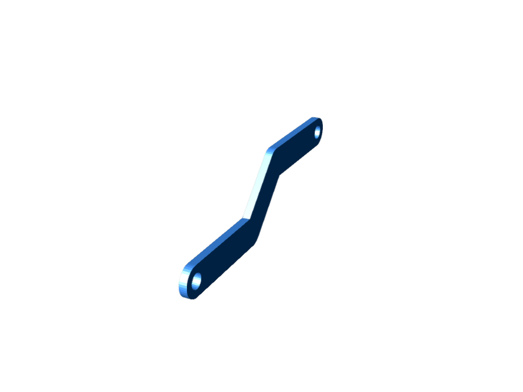
The Mechanics
The eyes are designed in CAD and 3D printed. The mechanism uses a linkage system where:
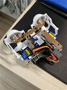
-2 Servos control the X and Y movement (looking up/down/left/right).
-2 Servos control the left and right eyelids independently.
I used standard, budget-friendly 9g micro servos (like the SG90 or MG90S). While they aren't industrial grade, they are perfect for a lightweight plastic mechanism like this.
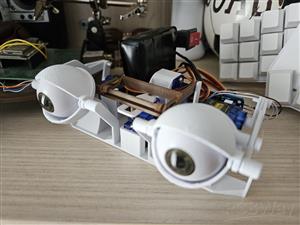
The Electronics
The brain of the operation is an ESP32.
I used a PCA9685 16-Channel Servo Driver.
Communication: The ESP32 sends commands to the PCA9685 via I2C.
Power: The PCA9685 has an external power terminal, which allows me to power the servos directly from a battery supply (preventing brownouts on the microcontroller).
The Control Logic
I used the Bluepad32 library to interface with the PS4 controller.
Left Analog Stick: Maps to the X/Y coordinate of the eyes.
L2/R2 Triggers: Linearly control the eyelids (analog blinking).
Triangle Button: Triggers a specific function I call "Sus Mode" which is a pre-programmed animation where the eyes squint and look suspicious.
4. Wiring & Schematic
The wiring is straightforward. The ESP32 powers the logic of the servo driver, while an external power source handles the load of the motors.
ESP32 3V3 → PCA9685 VCC
ESP32 GND → PCA9685 GND
ESP32 Pin 22 → PCA9685 SCL
ESP32 Pin 21 → PCA9685 SDA
Battery Power → PCA9685 Green Terminal Block

5. Bill of Materials (BOM)
1x ESP32 Development Board
1x PCA9685 PWM Driver
4x SG90 or MG90S Micro Servos (Generic cheap servos)
1x PS4 Controller (or compatible Bluetooth gamepad)
3D Printed Parts (PLA)
Wires & 5V Power Supply
ASSEMBLY INSTRUCTIONS:
1. Install Software
* Install Arduino IDE
* Add ESP32 board support to Arduino IDE
* Install required libraries: Adafruit PWM Servo Driver Library, Bluepad32
2. Initial Hardware Setup
* Wire the ESP32 and PCA9685 as described above.
3. Servo Calibration
* Connect the first servo to Channel 0:
PCA9685 -> Servo
V+ -> Red (5V)
GND -> Brown (GND)
Channel 0 -> Orange (Signal)
#include <Wire.h>
#include <Adafruit_PWMServoDriver.h>


Adafruit_PWMServoDriver pwm = Adafruit_PWMServoDriver();


#define SERVO_MIN 102
#define SERVO_MAX 512


#define SERVO_CENTER map(90, 0, 180, SERVO_MIN, SERVO_MAX)


#define SERVO_1 0
#define SERVO_2 1
#define SERVO_3 2
#define SERVO_4 3


void setup() {
  Serial.begin(115200);
  Wire.begin();
  pwm.begin();
  pwm.setPWMFreq(50);


  delay(500);
  uint16_t pulse = SERVO_CENTER;
  Serial.print("Centering servos to pulse: "); Serial.println(pulse);


  pwm.setPWM(SERVO_1, 0, pulse);
  pwm.setPWM(SERVO_2, 0, pulse);
  pwm.setPWM(SERVO_3, 0, pulse);
  pwm.setPWM(SERVO_4, 0, pulse);
}


void loop() {
}
4. Servo Range Test
* Test each servo channel:
* Channel 0 (X-axis): Find left/right limits (typically 70°-130°)
* Channel 1 (Y-axis): Find up/down limits (typically 70°-110°)
* Channel 2-3 (Eyelids): Test open/close (see below for values)
* The default values provided below should work for most setups. If you experience issues, use the angle\_tester to determine your own safe ranges and update them in `main.ino`.
#include <Wire.h>
#include <Adafruit_PWMServoDriver.h>


Adafruit_PWMServoDriver pwm = Adafruit_PWMServoDriver();


#define SERVO_MIN 102
#define SERVO_MAX 512
#define SERVO_CH   2


void setServoAngle(uint8_t ch, int angle) {
  angle = constrain(angle, 0, 180);
  uint16_t pulse = map(angle, 0, 180, SERVO_MIN, SERVO_MAX);
  pwm.setPWM(ch, 0, pulse);
  Serial.print("Servo "); Serial.print(ch);
  Serial.print(" -> "); Serial.print(angle); Serial.println("°");
}


void setup() {
  Serial.begin(115200);
  Wire.begin();
  pwm.begin();
  pwm.setPWMFreq(50);
  delay(200);


  setServoAngle(SERVO_CH, 90);
  Serial.println("Enter angle (0–180) and press ENTER:");
}


void loop() {
  if (Serial.available()) {
    String line = Serial.readStringUntil('\n');
    line.trim();
    if (line.length()) {
      int angle = line.toInt();
      if (angle < 0 || angle > 180) {
        Serial.println("Error: angle must be 0–180");
      } else {
        setServoAngle(SERVO_CH, angle);
      }
    }
  }
}
5. Software Configuration
const int xLeft = 130; // Your tested left limit
const int xRight = 70; // Your tested right limit
const int xMid = 95; // Your center position
const int yUp = 70; // Your tested up limit
const int yDown = 110; // Your tested down limit
6. Final Testing
* Upload main.ino
* Pair your Bluetooth gamepad (PS4 controller)
* Test controls:
* Left analog stick: Eye X/Y movement
* L2/R2 triggers: Left/right eyelid control
* Triangle button: "Sus mode" animation
## Assembly Instructions
1. Servo Mounting
* Mount all servos to the base. Ensure that the yAxisArm1 is connected to the y-axis servo before assembling the left eyelid servo.


2. Arm Connections
* Connect all arms to their corresponding servos.

* Connect both eyes to the base, being careful not to break the flexible but fragile base pins.

* Connect xAxisArm3.stl to the eyes, then xAxisArm2.stl to xAxisArm3.stl. After centering the servos, insert the protruding part of xAxisArm2.stl into the hole in xAxisArm1.stl.


* Connect yAxisArm3.stl to yAxisArm2.stl, then yAxisArm2.stl to xAxisArm1.stl (which should already be connected to the servo). Be cautious as these parts are flexible but can break under tension.


3. Eyelid Assembly
* Connect the eyelids to both the left and right eyes. The supporting part is designed to be flexible but can bend or break under excessive tension.
* Attach the upper and lower arms to the eyelids using the corresponding screws (long screw for the lower eyelid arm, short screw for the upper eyelid arm). First attach the upper arm, then the lower arm.
* For easier assembly, first attach the arms to the eyelids, then connect them to the base.
* Connect the eyeLidArmLeft.stl and eyeLidArmRight.stl to the eyelid arms using the eyeLidScrew.stl


4. Eyelid Servo Calibration
Important Note: The arm/horn mounted on the eyelid servo should not be perpendicular to the servo itself.
Calibration Steps:
* Ensure all servos are calibrated to 90 degrees.
* Close both eyelids.
* Mount the arm on the servo (eyelidarmleft/right) and slide it until the eyelids are closed. This should not move the motor; if it does, recalibrate the servo.
* Repeat the process for the other eye.
5. Final Adjustments
* The assembly is designed for a tight, snap-fit connection. Only the x and y axis arms require screws for the horns.
* Ensure all connections are secure and the mechanism moves smoothly without additional parts.


6. Additional Resources
* I found these doll eyes on AliExpress that fit perfectly into the eye.stl - https://a.aliexpress.com/_EHM9l0K
#include <Wire.h>
#include <Adafruit_PWMServoDriver.h>
#include <Bluepad32.h>

Adafruit_PWMServoDriver pwm;

// Eye limits and mid‑points
const int xLeft  = 130;
const int xRight =  70;
const int xMid   =  95;

const int yUp    =  70;
const int yDown  = 110;
const int yMid   = (yUp + yDown) / 2;  // 90

// radius
const int RADIUS = min(
  min(abs(xLeft - xMid), abs(xMid - xRight)),
  min(abs(yMid - yUp),    abs(yDown - yMid))
); // =20

// Servo channels
#define EYE_X     0
#define EYE_Y     1
#define LID_LEFT  2
#define LID_RIGHT 3

#define SERVO_MIN 102
#define SERVO_MAX 512

ControllerPtr controllers[BP32_MAX_GAMEPADS];

// animation state machine
bool susActive    = false;
int  sweepDir     = +1;   // +1 = left=>right, –1 = right=>left
int  passesLeft   = 0;
unsigned long stateStart = 0;
enum SusState { IDLE, PAUSE_END, CENTER_HOLD, SWEEP } susState = IDLE;

void onConnectedController(ControllerPtr ctl) {
  for (int i = 0; i < BP32_MAX_GAMEPADS; i++) {
    if (!controllers[i]) {
      controllers[i] = ctl;
      break;
    }
  }
}

void onDisconnectedController(ControllerPtr ctl) {
  for (int i = 0; i < BP32_MAX_GAMEPADS; i++) {
    if (controllers[i] == ctl) {
      controllers[i] = nullptr;
      break;
    }
  }
}

void setServo(int ch, int angle) {
  angle = constrain(angle, 0, 180);
  uint16_t pulse = map(angle, 0, 180, SERVO_MIN, SERVO_MAX);
  pwm.setPWM(ch, 0, pulse);
}

void setup() {
  Serial.begin(115200);
  Wire.begin();
  pwm.begin();
  pwm.setPWMFreq(50);
  delay(200);

  // center eyes, open lids
  setServo(EYE_X, xMid);
  setServo(EYE_Y, yMid);
  setServo(LID_LEFT,  50);
  setServo(LID_RIGHT, 90);

  BP32.setup(&onConnectedController, &onDisconnectedController);
  BP32.forgetBluetoothKeys();
}

void loop() {
  BP32.update();

  // detect triangle hold
  bool tri = false;
  for (auto ctl : controllers) {
    if (ctl && ctl->isConnected()) {
      tri = ctl->y();
      break;
    }
  }

  // enter/exit animation
  if (tri && !susActive) {
    susActive  = true;
    passesLeft = random(3,5);
    sweepDir   = +1;
    susState   = PAUSE_END;
    stateStart = millis();
  } else if (!tri && susActive) {
    susActive = false;
    susState  = IDLE;
    setServo(EYE_X, xMid);
    setServo(EYE_Y, yMid);
    setServo(LID_LEFT,  50);
    setServo(LID_RIGHT, 90);
  }

  if (susActive) {
    unsigned long dt = millis() - stateStart;

    switch (susState) {
      case PAUSE_END:
        setServo(EYE_X, sweepDir>0 ? xLeft : xRight);
        setServo(EYE_Y, yMid);
        setServo(LID_LEFT,  70);
        setServo(LID_RIGHT, 70);
        if (dt > 800) {
          susState   = SWEEP;
          stateStart = millis();
        }
        break;

      case SWEEP: {
        float frac = float(dt) / 5000.0f;
        if (frac > 1) frac = 1;
        int angleX = (sweepDir>0)
          ? xLeft  + round(frac * (xRight - xLeft))
          : xRight + round(frac * (xLeft  - xRight));
        setServo(EYE_X, angleX);
        setServo(EYE_Y, yMid);

        if (dt >= 5000) {
          sweepDir *= -1;
          passesLeft--;
          susState   = (passesLeft>0) ? PAUSE_END : CENTER_HOLD;
          stateStart = millis();
        }
        break;
      }

      case CENTER_HOLD:
        setServo(EYE_X, xMid);
        setServo(EYE_Y, yMid);
        setServo(LID_LEFT,  60);
        setServo(LID_RIGHT, 60);
        if (dt > 1500) {
          // restart
          passesLeft = random(2,3);
          sweepDir   = +1;
          susState   = PAUSE_END;
          stateStart = millis();
        }
        break;

      default:
      case IDLE:
        break;
    }
  }
  else {
    for (auto ctl : controllers) {
      if (!ctl || !ctl->isConnected()) continue;

      float jx = ctl->axisX() / 512.0f;
      float jy = ctl->axisY() / 512.0f;
      const float DZ = 0.10f;
      if (fabs(jx) < DZ) jx = 0;
      if (fabs(jy) < DZ) jy = 0;
      float mag = sqrt(jx*jx + jy*jy);
      if (mag > 1.0f) { jx /= mag; jy /= mag; }

      int angleX = xMid + round(jx * RADIUS);
      int angleY = yMid - round(jy * RADIUS);

      setServo(EYE_X, angleX);
      setServo(EYE_Y, angleY);
      setServo(LID_LEFT,  ctl->throttle() > 0 ? 90 : 50);
      setServo(LID_RIGHT, ctl->brake()    > 0 ? 50 : 90);
      break;
    }
  }
}
Animatronic Eyes
Project images are for reference only. Actual production is based on the manufacturing files on the project page.
Please review the designer's notes (e.g., PCB thickness) and select the appropriate options.
PCBWay is not responsible
for issues caused by unsuitable parameter selections.
For more important ordering information, please refer to
Read More


Raspberry Pi 5 7 Inch Touch Screen IPS 1024x600 HD LCD HDMI-compatible Display for RPI 4B 3B+ OPI 5 AIDA64 PC Secondary Screen(Without Speaker)
BUY NOW


- Comments(0)
- Likes(0)
More by Daniel Yordanov
-
 L.I.P.S. - Linear Interface for Paralysis Support
L.I.P.S. (Linear Interface for Paralysis Support) is a fully open-source, plug-and-play assistive de...
L.I.P.S. - Linear Interface for Paralysis Support
L.I.P.S. (Linear Interface for Paralysis Support) is a fully open-source, plug-and-play assistive de...
-
 Animatronic Eyes
1. What is this project?This is a robotics project I developed for one of my classes. It is a fully ...
Animatronic Eyes
1. What is this project?This is a robotics project I developed for one of my classes. It is a fully ...
-
 HEAT - Heater for Electronic Assembly & Testing
HEAT is a mains-powered, microcontroller-based smart hot-plate designed for electronics work such as...
HEAT - Heater for Electronic Assembly & Testing
HEAT is a mains-powered, microcontroller-based smart hot-plate designed for electronics work such as...
-
Programmable Mist Maker - XIAO / QT PY Extension
1061 2 1 -
RadioHAT - Raspberry Pi radio development platform
867 0 2 -
-
-
-
-
ARPS-2 – Arduino-Compatible Robot Project Shield for Arduino UNO
3323 0 6 -
A Compact Charging Breakout Board For Waveshare ESP32-C3
3933 3 8 -
AI-driven LoRa & LLM-enabled Kiosk & Food Delivery System
4320 2 2


