


|
KiCad 9.0 |
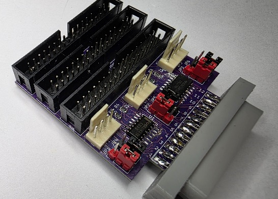
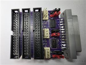
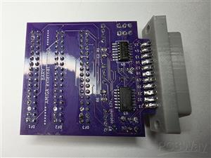
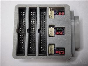
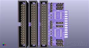
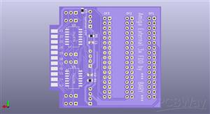
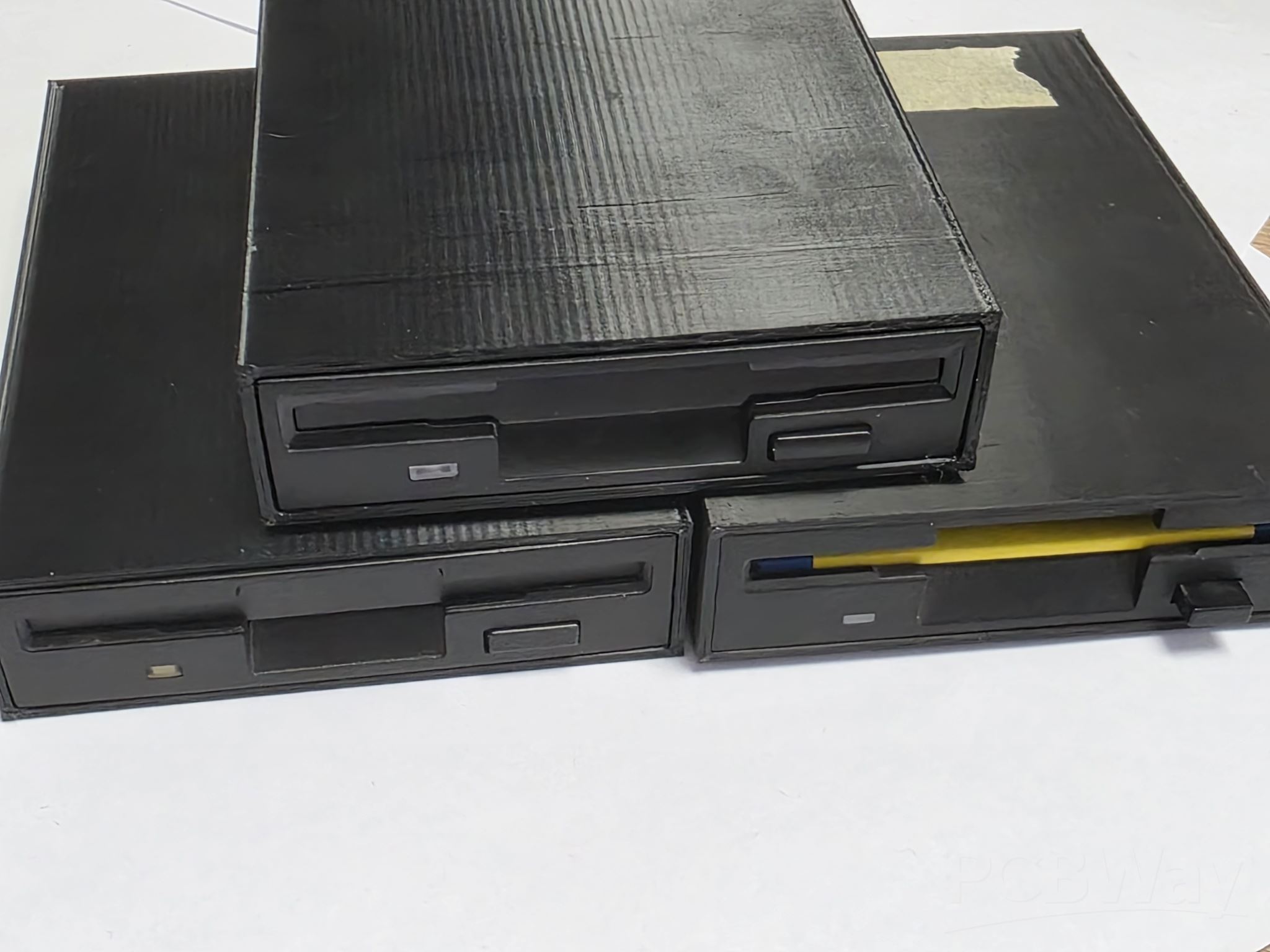
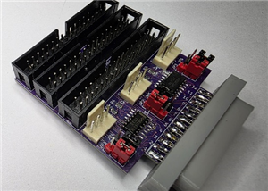
Amiga External 3x FDD-smd variant
Allows you to connect an original 1.44MB 3.5" PC FDD without any modifications or PC FDD modified for AMIGA. It also allows you to connect a GOTEK emulator (SFR1M44-U100 or SFR1M44-U100K).
(GOTEK, must be set to position S0)
You can connect 3 mechanics in any combination to FDD1, FDD2 and FDD3.
It all depends on the setup of the juper.
NOTICE:
Unconnected drives are displayed in the Workbench system as "DFx:????" it's not a bug, but a function of the adapter.
Settings:
For each drive port (FDD1,FDD2,FDD3)
there are two jumpers available to set the function of the adapter.
JP1 – JP4 for FDD1
JP2 – JP5 for FDD2
JP3 – JP6 for FDD3
The first jumper (JP1, JP2, JP3) is set by DISK CHANGE for the particular drive.
Jumper (JP1,JP2,JP3) positions 1-2 for Gotek or modified PC drive.
Jumper (JP1,JP2,JP3) positions 2-3 for unmodified PC drive.
Second jumper (JP4,JP5,JP6)
sets the SELx signal (DS0 or DS1)
Jumper (JP4,JP5,JP6) positions 1-2 for Gotek or modified PC drive.
Jumper (JP4,JP5,JP6) positions 2-3 for unmodified PC drive.
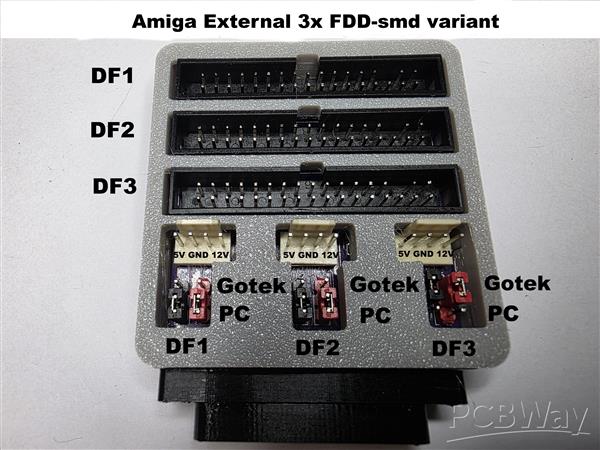
Both jumpers from a given pair (JP1-JP4,JP2-JP5,JP3-JP6) are always connected to the same position.
Unless we had a partially modified PC FDD where only the SEL signal was modified to DS0 and DISK CHANGE was not modified, then we would have to set: the first jumper position 2-3 and the second jumper position 1-2.
Important:
Jumper JP7 can be connected either with a piece of wire or with a 0 Ohm smd resistor, but do this only if you really need 12V for the drive. Standard FDDs use only 5V.
If you activate 12V, it can easily lead to the power connector being inserted backwards and subsequently destroying the drive or Gotek.
Many thanks:
Roman Breński, Jarosław Bieliński and Radosław Kujawa for this project.
http://romanworkshop.blutu.pl/elec/amiextfdd.htm
(DIY) C64iSTANBUL
https://www.pcbway.com/project/shareproject/AMIGA_EXTERNAL_FLOPPY_DISK_DRIVE_ADAPTER_bfe5cc33.html
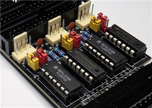
Components:
6x 3 pin 2.54mm (jumper) JP1 to JP6
2x IC 74LS38 SOP-14 U1,U4 (SN74LS38ADR)
2x IC 74LS74 SOP-14 U2,U3 (SN74LS74A)
6x resistor 2k2 Ohm 0805 R1 to R6
2x ceramic capacitor 100nf 0805 C1,C2
3x 4 pin 2.54mm KF2510-A (Male header) power FDD J1,J2,J3
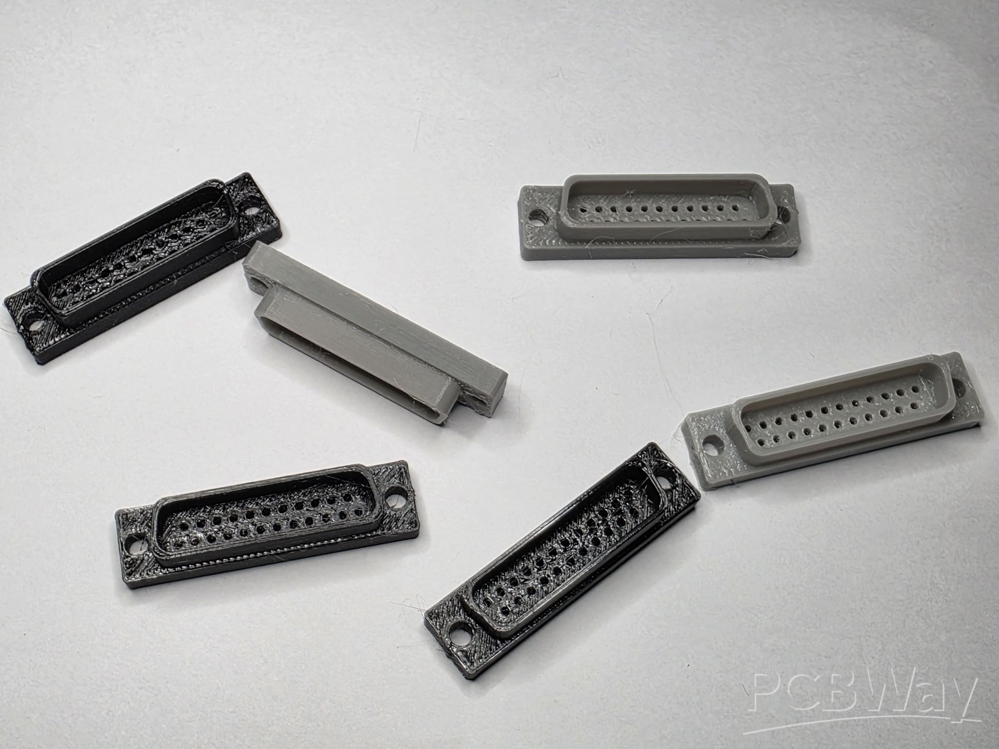
1x DB23 male (d-sub 23) J4
3x 2x17 (34 pin) 2.54 mm male Socket straight idc headers PCB
4x DIP 14 IC socket
You can make a d-sub 23 connector from d-sub 25 by cutting or 3D printing it and using pins from d-sub 25
https://www.thingiverse.com/thing:1238286
You can download the 3D design of the adapter cover here.
https://www.printables.com/model/1501583-cover-for-amiga-external-3x-fdd-smd-variant
If you would like to print a 3D cover for the 3.5 FDD, here you will find an STL file for several models of mechanics.
https://www.printables.com/model/1441622-cover-for-pc-35-fdd
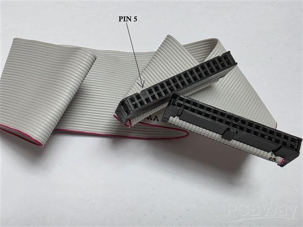
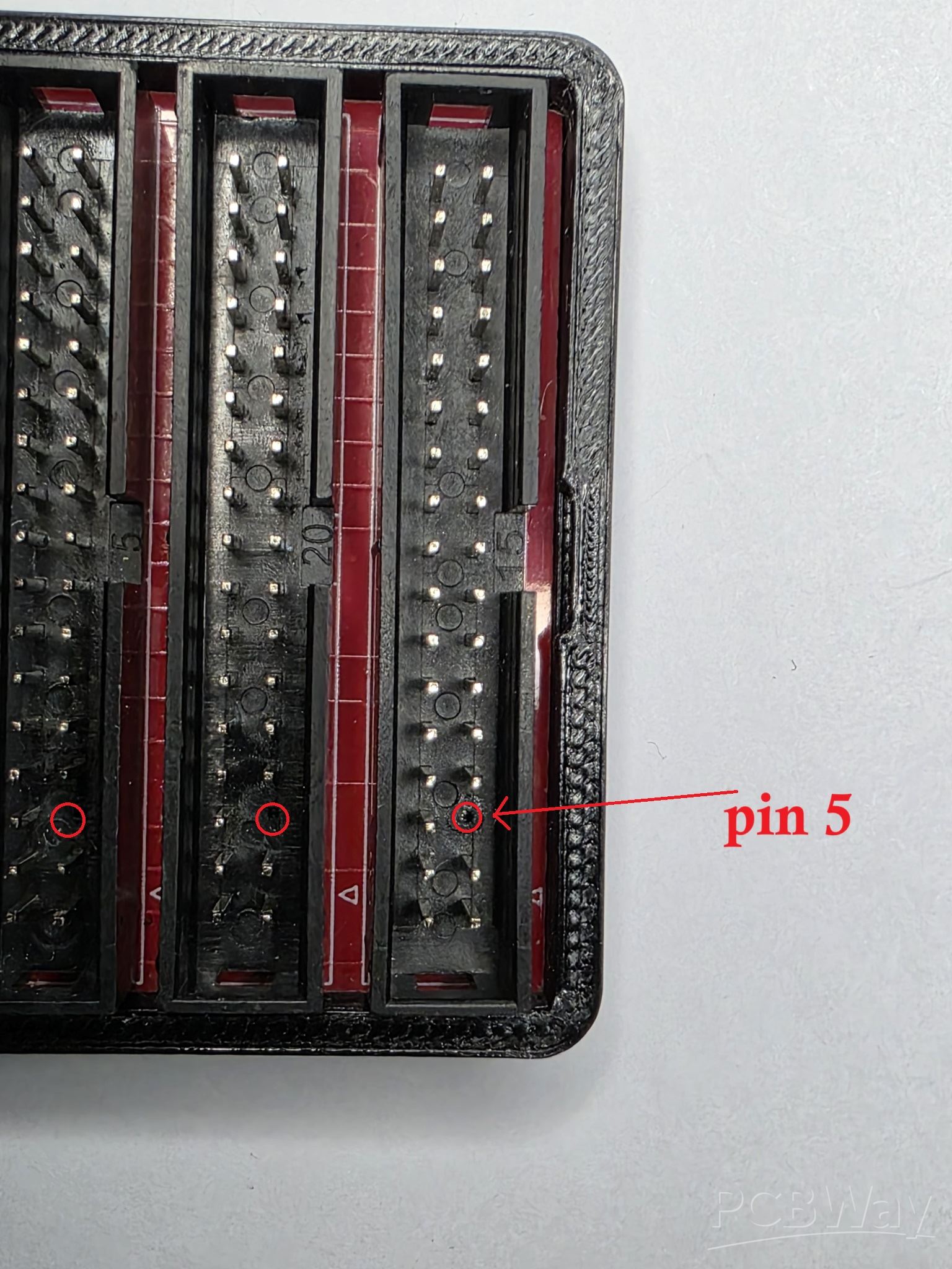
Advice:
I have seen flat cables that have pin 5 blinded on the connector. Therefore, it is better to remove pin number 5 from the connector on the PCB.
Amiga External 3x FDD-smd variant
Project images are for reference only. Actual production is based on the manufacturing files on the project page.
Please review the designer's notes (e.g., PCB thickness) and select the appropriate options.
PCBWay is not responsible
for issues caused by unsuitable parameter selections.
For more important ordering information, please refer to
Read More


Raspberry Pi 5 7 Inch Touch Screen IPS 1024x600 HD LCD HDMI-compatible Display for RPI 4B 3B+ OPI 5 AIDA64 PC Secondary Screen(Without Speaker)
BUY NOW


- Comments(2)
- Likes(5)
 More by Bary duke
-
 Amiga External 3x FDD (Floppy Disk Drive)
Allows you to connect an original 1.44MB 3.5" PC FDD without any modifications or PC FDD modified fo...
Amiga External 3x FDD (Floppy Disk Drive)
Allows you to connect an original 1.44MB 3.5" PC FDD without any modifications or PC FDD modified fo...
-
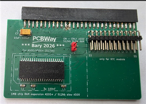 Amiga 500+ 1MB RAM+ connector modul RTC
Memory expansion for Amiga 500+ by 1MB or 512kb for Amiga 500 and connector modul RTC.You can instal...
Amiga 500+ 1MB RAM+ connector modul RTC
Memory expansion for Amiga 500+ by 1MB or 512kb for Amiga 500 and connector modul RTC.You can instal...
-
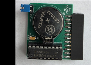 RTC for Amiga 500
RTC (Real Time Clock) module for the Amiga 500used on its own plugged into a trapdoor or you can use...
RTC for Amiga 500
RTC (Real Time Clock) module for the Amiga 500used on its own plugged into a trapdoor or you can use...
-
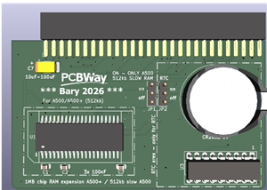 Amiga 500+ 1MB RAM+RTC (A500-512kb)
Memory expansion for Amiga 500+ by 1MB or 512kb for Amiga 500 + RTC (real time clock)I used 2x 512kb...
Amiga 500+ 1MB RAM+RTC (A500-512kb)
Memory expansion for Amiga 500+ by 1MB or 512kb for Amiga 500 + RTC (real time clock)I used 2x 512kb...
-
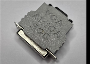 AMIGA RGB-VGA adapter with 9.5MHz Filters and 6dB Gain
RGB to VGA adapter for the Amiga A500-A600-A2000-A1200-A4000The THS7374 is the perfect choice for al...
AMIGA RGB-VGA adapter with 9.5MHz Filters and 6dB Gain
RGB to VGA adapter for the Amiga A500-A600-A2000-A1200-A4000The THS7374 is the perfect choice for al...
-
 AMIGA RGB-VGA adapter ( modified) with -SD/ED/HD/Full-HD Filters
This is a modified version of AMIRGB2VGA ULTIMATE from Ember EmberHeavyIndustries,https://www.pcbway...
AMIGA RGB-VGA adapter ( modified) with -SD/ED/HD/Full-HD Filters
This is a modified version of AMIRGB2VGA ULTIMATE from Ember EmberHeavyIndustries,https://www.pcbway...
-
 Amiga External 3x FDD-smd variant
Allows you to connect an original 1.44MB 3.5" PC FDD without any modifications or PC FDD modified fo...
Amiga External 3x FDD-smd variant
Allows you to connect an original 1.44MB 3.5" PC FDD without any modifications or PC FDD modified fo...
-
Programmable Mist Maker - XIAO / QT PY Extension
1066 2 1 -
RadioHAT - Raspberry Pi radio development platform
877 0 2 -
-
-
-
-
ARPS-2 – Arduino-Compatible Robot Project Shield for Arduino UNO
3330 0 6 -
A Compact Charging Breakout Board For Waveshare ESP32-C3
3938 3 8 -
AI-driven LoRa & LLM-enabled Kiosk & Food Delivery System
4326 2 2


