


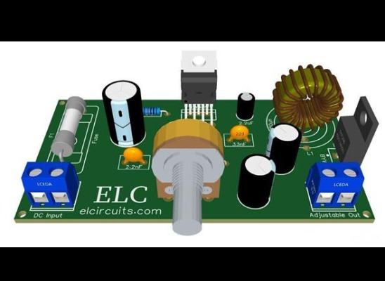


Adjustable Switching Power Supply 5.1 to 40V, 2.5 Amp using L4960
In this article, we present an adjustable power supply with a stabilized output that varies from 5.1 to 40V, with a current of 2.5 amps.
This one can also have its stabilized voltage fixed, everything will depend on the type of project you are going to use.
The adjustable power supply is based on IC L4960 which is a monolithic power switching regulator IC, delivering 2.5A at a voltage variable from 5V to 40V in step down configuration.
Features of the device include current limiting, soft start, thermal protection and 0 to 100% duty cycle for continuous operation mode.
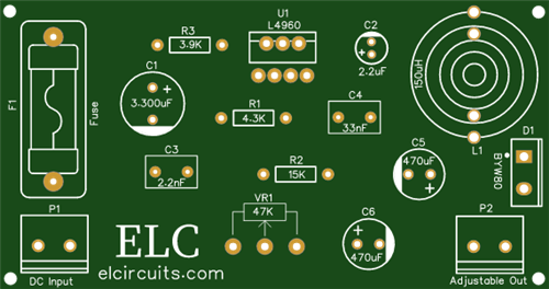
The complete schematic diagram of the power supply is shown below in Figure 1, it is a simple but complete power supply.
CIRCUIT OPERATION
The L4960 is a monolithic step down switching regulator providing output voltages from 5.1V to 40V and delivering 2.5A.
The regulation loop consists of a sawtooth oscillator, error amplifier, comparator and the output stage. An error signal is produced by comparing the output voltage with a precise 5.1V on-chip reference (zener zap trimmed to ± 2%).
This error signal is then compared with the sawtooth signal to generate the fixed frequency pulse width modulated pulses which drive the output stage.
The gain and frequency stability of the loop can be adjusted by an external RC network connected to pin 3.
Closing the loop directly gives an output voltage of 5.1V. Higher voltages are obtained by inserting a voltage divider.
Output overcurrent at switch on are prevented by the soft start function. The error amplifier output is initially clamped by the external capacitor Css and allowed to rise, linearly, as this capacitor is charged by a constant current source. Output overload protection is provided in the form of a current limiter.
The load current is sensed by an internal metal resistor connected to a comparator. When the load current exceeds a preset threshold this comparator sets a flip flop which disables the output stage and discharges the soft start capacitor.
A second comparator resets the flip flop when the voltage across the soft start capacitor has fallen to 0.4V.
The output stage is thus re-enabled and the output voltage rises under control of the soft start network.
If the overload condition is still present the limiter will trigger again when the threshold current is reached. The average short circuit current is limited to a safe value by the dead time introduced by the soft start network.
The thermal overload circuit disables circuit operation when the junction temperature reaches about 150°C and has hysteresis to prevent unstable conditions.
Efficient operation at switching frequencies up to 150KHz allows a reduction in the size and cost of external filter components.
The L4960 is mounted in a plastic Heptawatt power pack, and the pinouts are shown in Figure 2 below.


Adjustable Switching Power Supply 5.1 to 40V, 2.5 Amp using L4960
*PCBWay community is a sharing platform. We are not responsible for any design issues and parameter issues (board thickness, surface finish, etc.) you choose.


Raspberry Pi 5 7 Inch Touch Screen IPS 1024x600 HD LCD HDMI-compatible Display for RPI 4B 3B+ OPI 5 AIDA64 PC Secondary Screen(Without Speaker)
BUY NOW


- Comments(2)
- Likes(1)
More by Sayanik Mandal
-
 Time Delay Relay circuit using 555 timer IC
In this 555 timer project, I have shown how to make a time delay relay circuit using 555 timer IC to...
Time Delay Relay circuit using 555 timer IC
In this 555 timer project, I have shown how to make a time delay relay circuit using 555 timer IC to...
-
 Speed control of DC motor using PWM with 555 IC
In this 555 timer project, I have shown how to make speed control of DC motor using PWM with a 555 t...
Speed control of DC motor using PWM with 555 IC
In this 555 timer project, I have shown how to make speed control of DC motor using PWM with a 555 t...
-
Speed control of DC motor using PWM with 555 IC
In this 555 timer project, I have shown how to make speed control of DC motor using PWM with a 555 t...
-
 Atmega328P without Arduino PCB Design
Atmega328P microcontroller:The ATmega328P is a high-performance picoPower 8-bit AVR RISC-based micro...
Atmega328P without Arduino PCB Design
Atmega328P microcontroller:The ATmega328P is a high-performance picoPower 8-bit AVR RISC-based micro...
-
 Time Delay Relay circuit using 555 timer IC
In this electronics project, I have explained how to make a simple Water Level Indicator using the B...
Time Delay Relay circuit using 555 timer IC
In this electronics project, I have explained how to make a simple Water Level Indicator using the B...
-
 Time Delay Relay circuit using 555 timer IC
In this 555 timer project, I have shown how to make a time delay relay circuit using 555 timer IC to...
Time Delay Relay circuit using 555 timer IC
In this 555 timer project, I have shown how to make a time delay relay circuit using 555 timer IC to...
-
 LED chaser lights with 555 timer
n this electronics project, I have explained how to make simple LED chaser lights with CD4017 & ...
LED chaser lights with 555 timer
n this electronics project, I have explained how to make simple LED chaser lights with CD4017 & ...
-
 300 watt amplifier
Introduction to the AmplifierAn amplifier is an electronic device or circuit which is used to increa...
300 watt amplifier
Introduction to the AmplifierAn amplifier is an electronic device or circuit which is used to increa...
-
 amplification process
All Category amplifiers50W Power Amplifier With LM3886This is my second encounter with LM3886. I was...
amplification process
All Category amplifiers50W Power Amplifier With LM3886This is my second encounter with LM3886. I was...
-
 All Category amplifiers
50W Power Amplifier With LM3886This is my second encounter with LM3886. I was...
All Category amplifiers
All Category amplifiers50W Power Amplifier With LM3886This is my second encounter with LM3886. I was...
-
 Rotary switches controller
Rotary switches move in a circle and can stop in several positions. They are used to control many di...
Rotary switches controller
Rotary switches move in a circle and can stop in several positions. They are used to control many di...
-
 All Category amplifiers
50W Power Amplifier With LM3886This is my second encounter with LM3886. I was pleased with the sound...
All Category amplifiers
50W Power Amplifier With LM3886This is my second encounter with LM3886. I was pleased with the sound...
-
 300W RMS Power Amplifier - 2SC3858 and 2SA1494 Transistors
This amplifier has an excellent audio quality, and use four output power transistors, it reaches a s...
300W RMS Power Amplifier - 2SC3858 and 2SA1494 Transistors
This amplifier has an excellent audio quality, and use four output power transistors, it reaches a s...
-
 70W Stereo HI-FI Power Amplifier - High Fidelity using two TDA2050 IC's + PCB
The TDA2050 Integrated CircuitsThe TDA2050 is a monolithic integrated circuit in a Pentawatt? packag...
70W Stereo HI-FI Power Amplifier - High Fidelity using two TDA2050 IC's + PCB
The TDA2050 Integrated CircuitsThe TDA2050 is a monolithic integrated circuit in a Pentawatt? packag...
-
 Adjustable Switching Power Supply 5.1 to 40V, 2.5 Amp using L4960
In this article, we present an adjustable power supply with a stabilized output that varies from 5.1...
Adjustable Switching Power Supply 5.1 to 40V, 2.5 Amp using L4960
In this article, we present an adjustable power supply with a stabilized output that varies from 5.1...
-
 Christmas tree with arduino uno
Christmas tree with Arduino UNOStep 1: Circuit DiagramThe project is super easy for everyone to make...
Christmas tree with arduino uno
Christmas tree with Arduino UNOStep 1: Circuit DiagramThe project is super easy for everyone to make...
-
 Christmas tree with arduino uno
Step 1: Circuit DiagramThe project is super easy for everyone to make, and no specific knowledge is ...
Christmas tree with arduino uno
Step 1: Circuit DiagramThe project is super easy for everyone to make, and no specific knowledge is ...
-
 rgb LED Controller
Hi guys in this project I shall show you that how you can make a RGB Light cntoller. Here is the PCB...
rgb LED Controller
Hi guys in this project I shall show you that how you can make a RGB Light cntoller. Here is the PCB...
-
Programmable Mist Maker - XIAO / QT PY Extension
117 0 0 -
RadioHAT - Raspberry Pi radio development platform
139 0 1 -
-
-
-
-
ARPS-2 – Arduino-Compatible Robot Project Shield for Arduino UNO
2743 0 5 -
A Compact Charging Breakout Board For Waveshare ESP32-C3
3243 3 8 -
AI-driven LoRa & LLM-enabled Kiosk & Food Delivery System
3501 2 2


