



ATmega4809-A Breakout Board
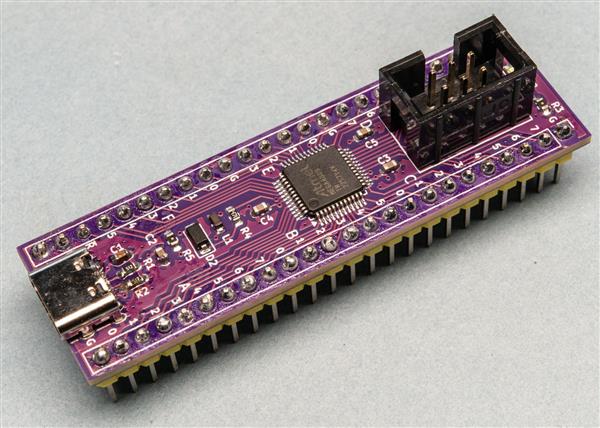
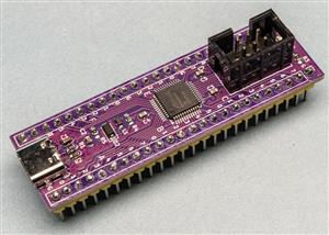
A breakout board that allows you to easily work with the AVR 0-series ATmega4809-A microcontroller. This is a QFP format chip, so this board breaks out the pins to two rows of 2.54mm pitch headers, effectively turning it into a DIP package.
Headers are provided for programming the microcontroller via UPDI, either via a six-pin (3x2) connector compatible with the Atmel-ICE or via serial. The latter has a diode between the TX and RX pins.
A footprint is provided for a USB-C socket. This is used just for powering the board at 5V. Or you can power it via the header pins. (No reverse current protection is provided.)
Gerbers, schematics and other files, including a sample program and make file, are available on GitHub.
The BOM and Centroid files contain all the details for the surface-mount components, but not the USB socket or header pins.
Full details are available on Machina Speculatrix, published via Medium and Substack (subscriptions required), but here are some highlights.
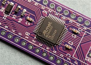
I figured it would be useful to have onboard decoupling capacitors for the chip’s power pins. I put them near the pins themselves and also across the power input to the board.
As for power, you can provide it via the power pins on the header rows (there are VCC and GND pins at the ends of each row) or through a USB-C socket. The socket is wired purely for power, with the CC1 and CC2 pins pulled low via 5.1KΩ resistors.
One compromise I made was to connect AVCC (the voltage supply for analogue pins) to VCC, via a 10µH inductor. This means I can’t use a separate VCC reference voltage for analogue stuff, which is fine by me because I’m mostly interested in digital signals. Maybe I could break this out separately on a version B, with a jumper to give you the choice. But that’s for the future.
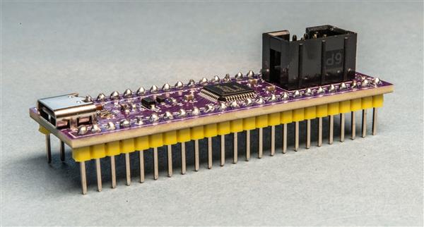
The board’s pins span the same width as a standard 15.24mm wide IC — ie, the same as the DIP-40 version of the microcontroller — although it’s significantly longer.
The files here are for the revised design of the board which fixes a couple of minor errors I made on the original.
ATmega4809-A Breakout Board
Project images are for reference only. Actual production is based on the manufacturing files on the project page.
Please review the designer's notes (e.g., PCB thickness) and select the appropriate options.
PCBWay is not responsible
for issues caused by unsuitable parameter selections.
For more important ordering information, please refer to
Read More









Raspberry Pi 5 7 Inch Touch Screen IPS 1024x600 HD LCD HDMI-compatible Display for RPI 4B 3B+ OPI 5 AIDA64 PC Secondary Screen(Without Speaker)
BUY NOW


- Comments(0)
- Likes(0)
More by Steve Mansfield-Devine
-
 SmartMatrix: networked parallel printer interface
The Raspberry Pi Pico 2W-based SmartMatrix adapter uses the microcontroller to convert serial or net...
SmartMatrix: networked parallel printer interface
The Raspberry Pi Pico 2W-based SmartMatrix adapter uses the microcontroller to convert serial or net...
-
 ATmega4809-A Breakout Board
A breakout board that allows you to easily work with the AVR 0-series ATmega4809-A microcontroller. ...
ATmega4809-A Breakout Board
A breakout board that allows you to easily work with the AVR 0-series ATmega4809-A microcontroller. ...
-
 Infrared IoT hub for home automation - ESP32 version
I created this as a way of experimenting with using IR signals to communicate with Internet of Thing...
Infrared IoT hub for home automation - ESP32 version
I created this as a way of experimenting with using IR signals to communicate with Internet of Thing...
-
SmallOLED - Live PC Stats, Animated Clocks & Audio Visualizer
756 0 3 -
"Talking Multimeter": Arduino-Based Speech Add-on for Multimeters with SCPI Protocol
429 0 1 -
Programmable Mist Maker - XIAO / QT PY Extension
2881 2 3 -
RadioHAT - Raspberry Pi radio development platform
2463 0 4 -
-
-
-
ARPS-2 – Arduino-Compatible Robot Project Shield for Arduino UNO
4547 0 6


















