


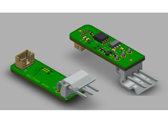


ADC2PWM PCB
ADC2PWM
Usage example is replacing a flowmeter with a pressure sensor in a coffee maker.
#include <Arduino.h>

#define PWM_PIN PB1
#define ADC_PIN 1 // PB2

void setup() {
  // Set the PWM pin as output
  DDRB |= _BV(PWM_PIN);

  // Configure Timer/Counter0
  TCCR0A = 0x00;
  TCCR0A |= _BV(WGM00) | _BV(COM0A0)| _BV(COM0B1);

  TCCR0B = 0x00;
  TCCR0B |= _BV(CS02); // Set the PWM frequency to 122 Hz

  TCNT0 = 0;
  OCR0B = 0;

  // ADC configuration
  ADMUX = _BV(MUX0);          // Select ADC input channel 1 (PB2)
  ADCSRA = _BV(ADEN) |        // Enable ADC
           _BV(ADPS2) |       // Set prescaler to 64 (125kHz with 8MHz clock)
           _BV(ADPS1);
}

void loop() {
  // Start ADC conversion
  ADCSRA |= _BV(ADSC);

  // Wait for conversion to complete
  while (ADCSRA & _BV(ADSC));

  // Read ADC value (10-bit value)
  uint16_t adcValue = ADC;

  // Scale ADC value to match OCR1A range (0 to OCR1C)
  uint8_t pwmValue = adcValue >> 2;

  OCR0B = pwmValue;
}
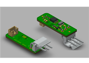
ADC2PWM PCB
Project images are for reference only. Actual production is based on the manufacturing files on the project page.
Please review the designer's notes (e.g., PCB thickness) and select the appropriate options.
PCBWay is not responsible
for issues caused by unsuitable parameter selections.
For more important ordering information, please refer to
Read More


Raspberry Pi 5 7 Inch Touch Screen IPS 1024x600 HD LCD HDMI-compatible Display for RPI 4B 3B+ OPI 5 AIDA64 PC Secondary Screen(Without Speaker)
BUY NOW

- Comments(0)
- Likes(0)
 More by The Vas
-
 ToFnLED v1
ToF sensor and RGB LED controlled via I2C bus are placed on a small board for use in espresso coffee...
ToFnLED v1
ToF sensor and RGB LED controlled via I2C bus are placed on a small board for use in espresso coffee...
-
 ADC and Screen adapter for CRM3007L
Adapter board with ADS1115 and FPC connector for CrowPanel 1.28inch-HMI ESP32 Round Touch Knob Scree...
ADC and Screen adapter for CRM3007L
Adapter board with ADS1115 and FPC connector for CrowPanel 1.28inch-HMI ESP32 Round Touch Knob Scree...
-
 RedPill for GaggiaBoard V2/V3
ESP32-S3 pill for GaggiaBoard V2/V3
RedPill for GaggiaBoard V2/V3
ESP32-S3 pill for GaggiaBoard V2/V3
-
 XJK1310-BT
Adding Bluetooth to XJK1310 scales.IMPORTANT: PCB thickness must be 1.0 mm.
XJK1310-BT
Adding Bluetooth to XJK1310 scales.IMPORTANT: PCB thickness must be 1.0 mm.
-
 CleverBoard
A specialized control board based on ESP32-C6.NOTE: The design isn't currently verified, no FW avail...
CleverBoard
A specialized control board based on ESP32-C6.NOTE: The design isn't currently verified, no FW avail...
-
 BT for CK2150
Add Bluetooth to CK2150 scales
BT for CK2150
Add Bluetooth to CK2150 scales
-
 Generic AC dimmer
 with zero-cross detector.LCSC BOM and Centroid are in Gerber ZIP
Generic AC dimmer
Generic AC dimmer with zero-cross detector.LCSC BOM and Centroid are in Gerber ZIP
-
 ADC2PWM PCB
ADC2PWMUsage example is replacing a flowmeter with a pressure sensor in a coffee maker.
ADC2PWM PCB
ADC2PWMUsage example is replacing a flowmeter with a pressure sensor in a coffee maker.
-
 FPC scales cable adapter
5 pin JST adapter for Dual HX711 scales board with FPC connector
FPC scales cable adapter
5 pin JST adapter for Dual HX711 scales board with FPC connector
-
 GaggiaBoard_V2.1
Gerber zip contains LCSC BOM and Centroid file
GaggiaBoard_V2.1
GaggiaBoard_V2.1Gerber zip contains LCSC BOM and Centroid file
-
 Dual HX711 scales board with FPC connector
Compact dual HX711 board for electronic scales with FPC connector.Gerber zip contains LCSC BOM and C...
Dual HX711 scales board with FPC connector
Compact dual HX711 board for electronic scales with FPC connector.Gerber zip contains LCSC BOM and C...
-
 GaggiaBoard_V3
Gerber zip contains LCSC BOM and Centroid fileWARNING!Most of SMD components are place...
GaggiaBoard_V3
GaggiaBoard_V3Gerber zip contains LCSC BOM and Centroid fileWARNING!Most of SMD components are place...
-
 Dual HX711 scales board
Compact dual HX711 board for electronic scales.Allows common or separate VCC and VDD, as well as com...
Dual HX711 scales board
Compact dual HX711 board for electronic scales.Allows common or separate VCC and VDD, as well as com...
-
Programmable Mist Maker - XIAO / QT PY Extension
1106 2 1 -
RadioHAT - Raspberry Pi radio development platform
917 0 2 -
-
-
-
-
ARPS-2 – Arduino-Compatible Robot Project Shield for Arduino UNO
3348 0 6 -
A Compact Charging Breakout Board For Waveshare ESP32-C3
3963 3 8 -
AI-driven LoRa & LLM-enabled Kiosk & Food Delivery System
4354 2 2


