


5A adjustable voltage regulator circuit 0-30 volts
5A adjustable voltage regulator circuit 0-30 volts
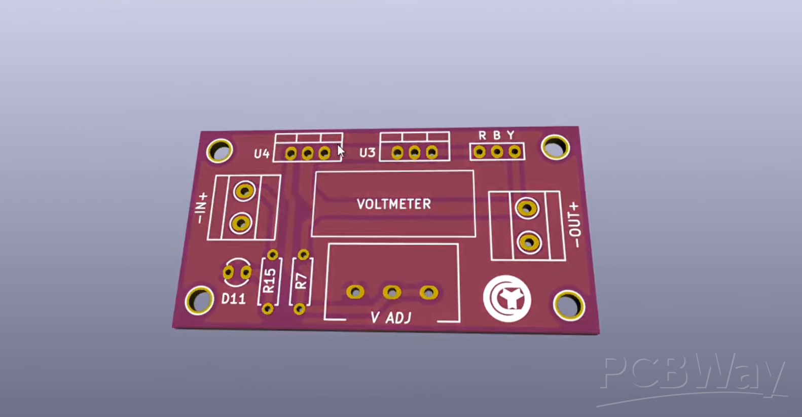
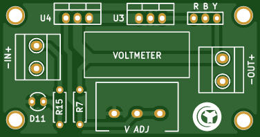
hi guys today I will be making a simple and Powerful adjustable voltage regulator circuit which will provide output from 0 to 30 volts with up to 5 amperes output current you just require some few components like lm338 voltage regulator lm7812 voltage regulator 220 ohms resistor 10 kilo ohms resistor 5 kilo ohms potentiometer 2 pin terminal connectors 305 mm LED 3 pin header connector and 0.36 inch DC voltmeter I also prepared simple circuit diagram of the circuit in CAD as you can see here goes the DC input of 30 volts and 5 amperes clear LED with resistor for power indicator I used LM double three eight voltage regulator which provides maximum 5 amperes output and output voltage can be adjusted with this 5 kilo ohms potentiometer and here 220 ohms resistor for sensing output voltage I also use 12 volt regulator to power up the DC voltmeter so that output voltage can be monitored and controlled properly and here you get output from 0 to 30 volts at 5 amperes I clean the PCB with isopropyl alcohol and here our PCB is looking nice and clean I use normal sized heatsink for heat dissipation also used silicon pads for insulation for these both voltage regulators use screws with dust plastic bushes also called M3 washers it is used to fully isolate component from heatsink I simply place the PCB with components at their place and then soldered all the beans of both components also connected voltmeter in its connector and fixed it with double-sided tape at its place now our circuit is fully ready so let's prepare it for test connect output and input wires also add a potentiometer knob I powered the circuit with 24 volt 5 ampere smps and the output can be simply adjusted with this potentiometer I set the voltage at 12.4 Volts for testing the circuit also I use multimeter to monitor the amperes drawn by the load I used some small piece of nechrome wire for testing as you can see load even touched to above 5 amperes and there is about 1.2 to 1.3 volts voltage drop in the circuit which is quite acceptable you can also connected power LEDs and brightness can be controlled by decreasing or increasing voltage.
5A adjustable voltage regulator circuit 0-30 volts
*PCBWay community is a sharing platform. We are not responsible for any design issues and parameter issues (board thickness, surface finish, etc.) you choose.


Raspberry Pi 5 7 Inch Touch Screen IPS 1024x600 HD LCD HDMI-compatible Display for RPI 4B 3B+ OPI 5 AIDA64 PC Secondary Screen(Without Speaker)
BUY NOW


- Comments(0)
- Likes(1)
More by Beytullah Gültepe
-
 STM32F101 Card
STM32F101 devices use the Cortex-M3 core, with a maximum CPU speed of 36 MHz. The port...
STM32F101 Card
STM32F101 CardSTM32F101 devices use the Cortex-M3 core, with a maximum CPU speed of 36 MHz. The port...
-
 5V Regulator
 Is to keep a constant output voltage even if the input voltage changes, why is it impor...
5V Regulator
5V Regulator Is to keep a constant output voltage even if the input voltage changes, why is it impor...
-
 12V Battery Level Indicator New
12V BATTERY LEVEL INDICATOR CIRCUIT NEW The circuit I designed is suitable for 12V batteries. You in...
12V Battery Level Indicator New
12V BATTERY LEVEL INDICATOR CIRCUIT NEW The circuit I designed is suitable for 12V batteries. You in...
-
 -Voltage regulator #220v ac to dc 3v,6v,12v,24v,36v,48v,68v,98v,110v,120v. Auto volt
VOLTAGE REGULATOR LM317The LM217, LM317 are monolithic integrated circuits in TO-220, TO-220FP and D...
-Voltage regulator #220v ac to dc 3v,6v,12v,24v,36v,48v,68v,98v,110v,120v. Auto volt
VOLTAGE REGULATOR LM317The LM217, LM317 are monolithic integrated circuits in TO-220, TO-220FP and D...
-
 -LED Zener Diode components Tester
ZENER TESTERMT3608 2A Max DC-DC Progressive Power Module product is an amplifier board designed for ...
-LED Zener Diode components Tester
ZENER TESTERMT3608 2A Max DC-DC Progressive Power Module product is an amplifier board designed for ...
-
 -Voltage DC Boost Converter
Voltage Doubler DC Boost Converter Hello everyone,In this project, I designed a DC boost converter a...
-Voltage DC Boost Converter
Voltage Doubler DC Boost Converter Hello everyone,In this project, I designed a DC boost converter a...
-
 -Simple 30A adjustable voltage regulator 0-30 volts
-Simple 30A adjustable voltage regulator 0-30 volts
-Simple 30A adjustable voltage regulator 0-30 volts
-
 -Signal Generator
SIGNAL GENERATORThe 4017 IC is a 16-legged IC.The enable, reset, carry out pins on the 4017 IC are c...
-Signal Generator
SIGNAL GENERATORThe 4017 IC is a 16-legged IC.The enable, reset, carry out pins on the 4017 IC are c...
-
 -Led Sequencer
LED SEQUENCERCD4017CD4017 has the same leg connections as 7400 and 74ls00 have the same features a...
-Led Sequencer
LED SEQUENCERCD4017CD4017 has the same leg connections as 7400 and 74ls00 have the same features a...
-
 -14-28V to 12V-3.5A 1MHz DC to DC Step-Down Converter
Circuit AnalysisFigure 1 shows the schematic diagram. The heart of the circuit is the TPS54332DDA ch...
-14-28V to 12V-3.5A 1MHz DC to DC Step-Down Converter
Circuit AnalysisFigure 1 shows the schematic diagram. The heart of the circuit is the TPS54332DDA ch...
-
 -Simple 12v to 220v mini inverter using 4047 IC
IRFZ44Fifth Generation HEXFETs from International Rectifier utilize advanced processing techniques t...
-Simple 12v to 220v mini inverter using 4047 IC
IRFZ44Fifth Generation HEXFETs from International Rectifier utilize advanced processing techniques t...
-
 -Buck Converter LM2596
BUCK CONVERTER LM2596 Voltage Reducer Adjustable Power Module “With the LM2596 Adjustable DC-DC Conv...
-Buck Converter LM2596
BUCK CONVERTER LM2596 Voltage Reducer Adjustable Power Module “With the LM2596 Adjustable DC-DC Conv...
-
 -Automatic Proximity Switch
IR Receiver Modules for Remote Control SystemsFEATURES • Very low supply current • Photo detector an...
-Automatic Proximity Switch
IR Receiver Modules for Remote Control SystemsFEATURES • Very low supply current • Photo detector an...
-
 -12V BATTERY LEVEL INDICATOR CIRCUIT
12V BATTERY LEVEL INDICATOR CIRCUIT In the circuit I designed, I made a battery level indicator usin...
-12V BATTERY LEVEL INDICATOR CIRCUIT
12V BATTERY LEVEL INDICATOR CIRCUIT In the circuit I designed, I made a battery level indicator usin...
-
 5A adjustable voltage regulator circuit 0-30 volts
hi guys today I will be making a simple and Powerf...
5A adjustable voltage regulator circuit 0-30 volts
5A adjustable voltage regulator circuit 0-30 voltshi guys today I will be making a simple and Powerf...
-
 Schematic 6 Stage Led Chaser Using Transistor
Schematic 6 Stage Led Chaser Using Transistor Thanks to...
Schematic 6 Stage Led Chaser Using Transistor
Schematic 6 Stage Led Chaser Using TransistorSchematic 6 Stage Led Chaser Using Transistor Thanks to...
-
 how to make Automatic cut off 12 volt battery charger
NE555 SA555 - SE555Features■ Low turn-off time■ Maximum operating frequency greater than500 kHz■ Tim...
how to make Automatic cut off 12 volt battery charger
NE555 SA555 - SE555Features■ Low turn-off time■ Maximum operating frequency greater than500 kHz■ Tim...
-
 FM RADIO BEYTSEL
Fm Radio Receiver 4 TransistorsFm Radio Receiver 4 TransistorsHere is a very simple and effective ci...
FM RADIO BEYTSEL
Fm Radio Receiver 4 TransistorsFm Radio Receiver 4 TransistorsHere is a very simple and effective ci...
-
-
ARPS-2 – Arduino-Compatible Robot Project Shield for Arduino UNO
1283 0 4 -
A Compact Charging Breakout Board For Waveshare ESP32-C3
1796 3 7 -
AI-driven LoRa & LLM-enabled Kiosk & Food Delivery System
1782 2 0 -
-
-
-
ESP32-C3 BLE Keyboard - Battery Powered with USB-C Charging
1963 0 1 -


