


|
Autodesk Fusion 360Autodesk
|
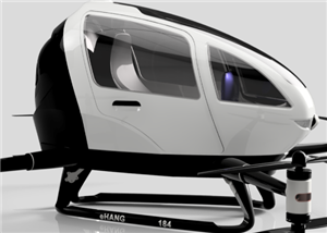
EHANG 184 Fully Customizable 3D Drone Project – For Intermediate & Advanced CAD Users
Project Overview
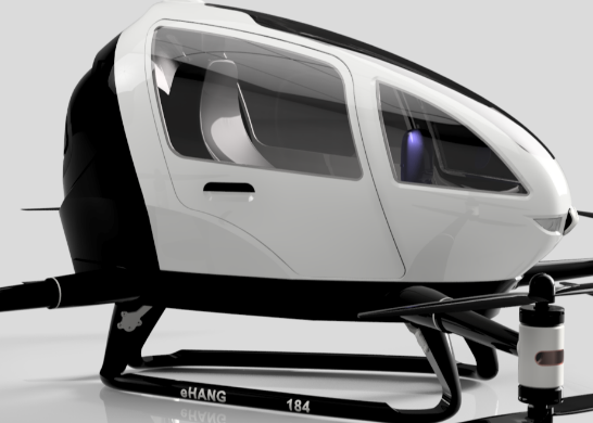
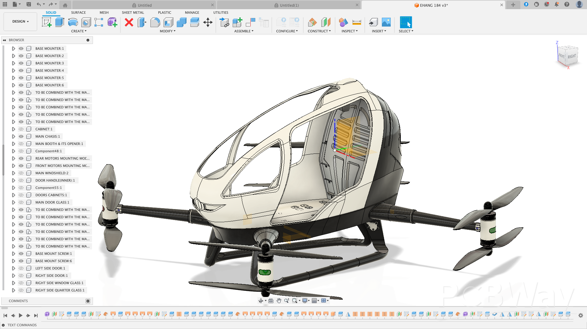
This EHANG 184 drone model, inspired by EHANG, a leader in autonomous aerial vehicles, is a highly detailed, modular, and fully customizable 3D CAD project. I designed this drone entirely from scratch, without any blueprints, relying solely on observation, research, and CAD skills to recreate every component accurately. Every part—from propellers and motors to cockpit details and landing gears—is editable, allowing intermediate and advanced users to modify, thicken, or redesign parts for their own builds. The main chassis is intentionally left unthickened, and locking mechanisms are omitted, giving users complete freedom to experiment and innovate.
Acknowledgment: This project is inspired by and based on the EHANG 184, a pioneering autonomous aerial vehicle developed by EHANG, a leading company in passenger drones and urban air mobility solutions. Full credit goes to EHANG for the original design concept; this 3D model is intended solely for educational, experimental, and non-commercial purposes.
Important Note: The main chassis has been intentionally left unthickened, and locking mechanisms have not been designed. This allows users the flexibility to modify, reinforce, or adapt the drone to their specific needs. Beginners and intermediate users are encouraged to explore, iterate, and apply their own design improvements. To help with this, I have provided accompanying YouTube tutorials sharing the tips, tricks, and techniques used to design this drone in Fusion 360.
Component Overview and Functions:
. Propellers (EHANG 184 PROPELLER .stl): Designed for aerodynamic efficiency and precise fit on the rotor hubs. Users can customize size, pitch, or blade shape to experiment with flight dynamics.
. Navigation Lights (EHANG 184 NAVIGATION LIGHT.stl): Provides visual orientation cues. Fully customizable in size, position, or design for aesthetic or functional purposes.
. Motor Mounting Hubs (Front & Rear) (EHANG 184 MOTOR MOUNTING HUB.stl): Securely hold the front and rear motors in place. Users can adjust hub dimensions, add reinforcements, or integrate new motor types.
. Main Seat & Support (EHANG 184 MAIN SEAT & MAIN SEAT SUPPORT.stl): Represents the cockpit seating area. The support ensures proper placement; users can adjust scale, add textures, or design alternative seating arrangements.
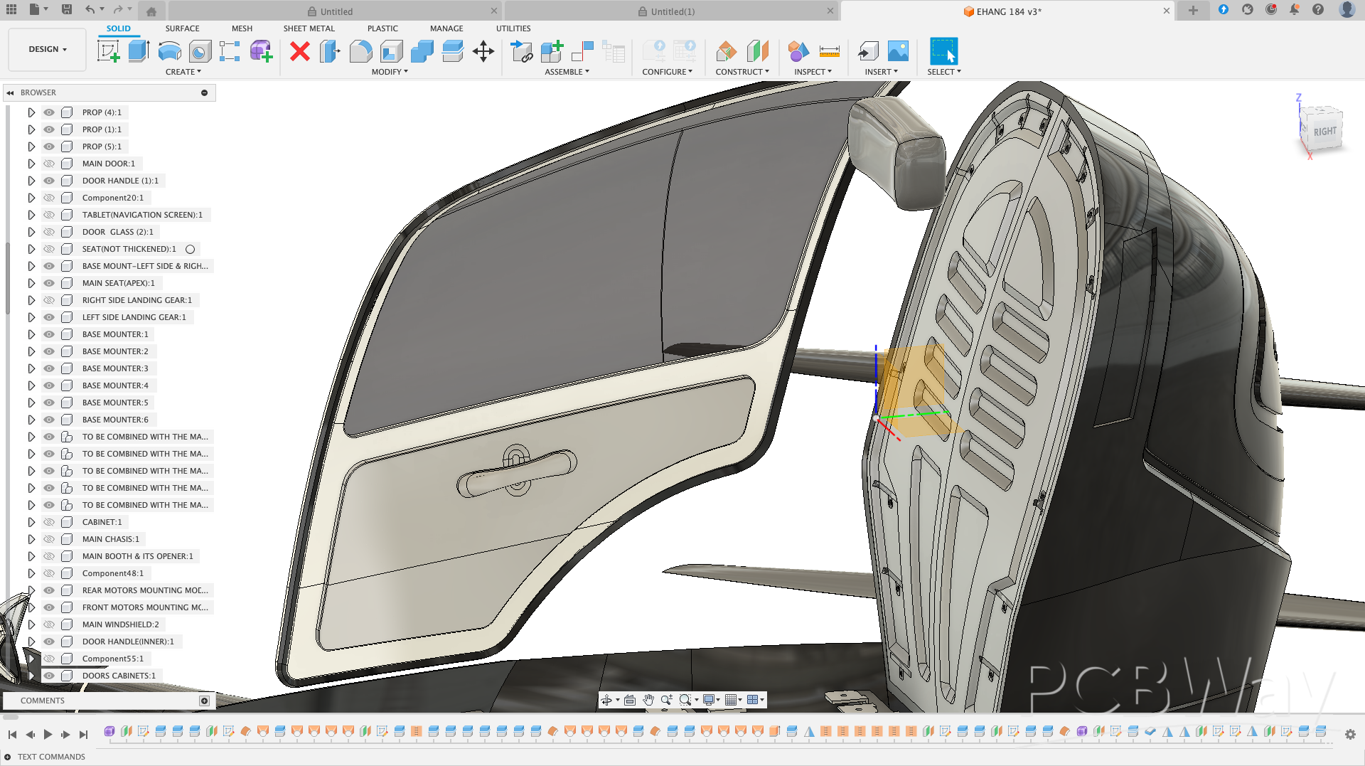
. Main Door & Components (EHANG 184 MAIN DOOR, DOOR HANDLE, DOOR GLASS, DOOR CABINET.stl): Accurately modeled cockpit door assembly. Users can design locking mechanisms, hinges, or alter panel thicknesses for functional or aesthetic purposes. Below is the screenshot of the door.
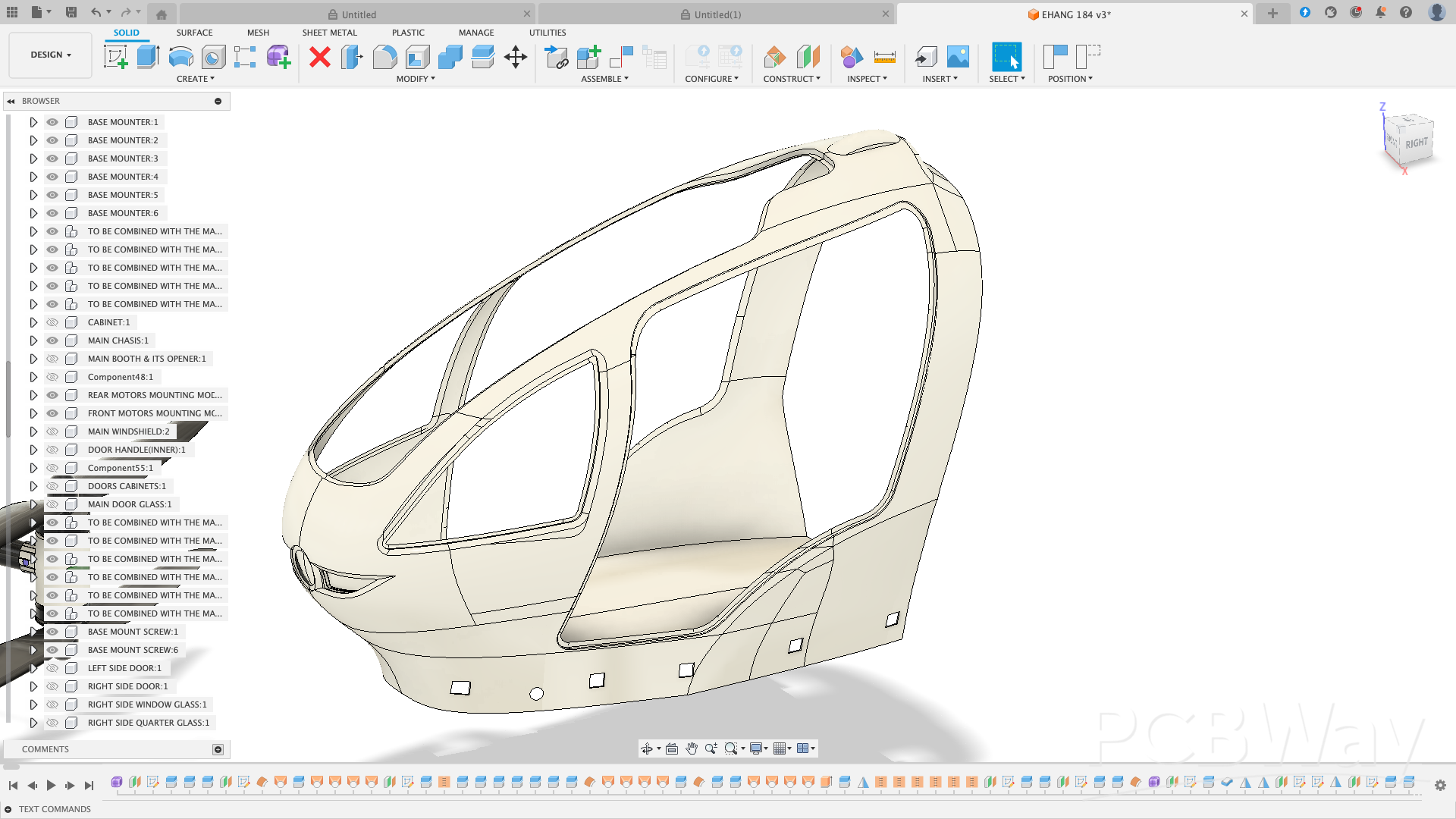
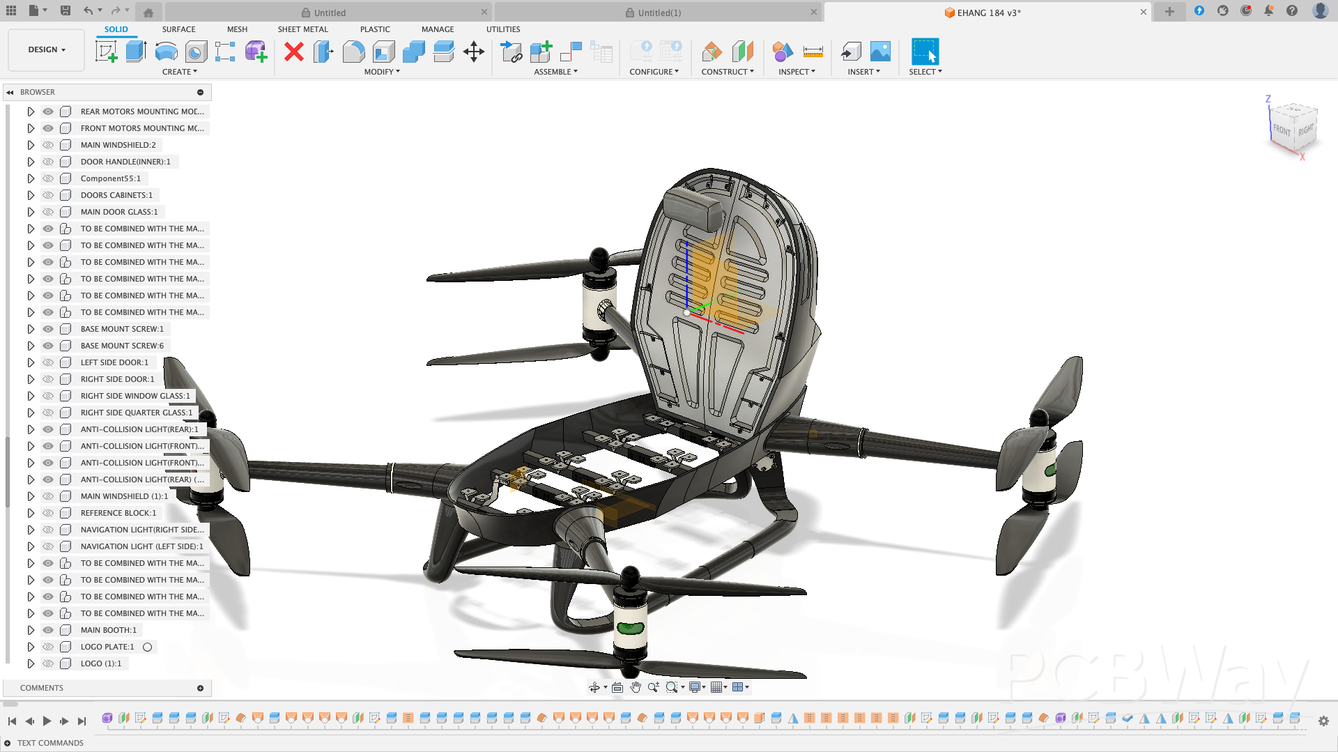
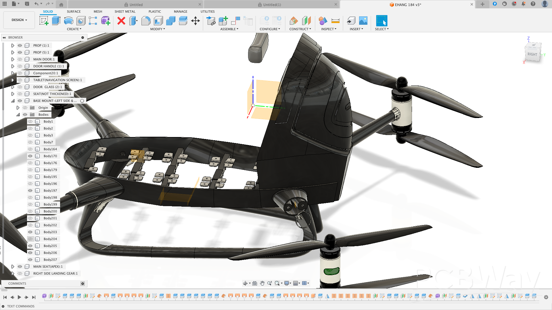
. Main Chassis & Supports (EHANG 184 MAIN CHASSIS & MAIN CHASSIS SUPPORT.stl): Core structural frame. Left unthickened to allow users to reinforce or modify as needed for weight, material choice, or integration of electronics. Below is the image of the main chassis. Please carefully observe it.
. Cockpit Booth & Cabinet (EHANG 184 MAIN BOOTH, BOOTH CABINET, BOOTH LID, BOOTH HANDLE.stl): Interior cockpit detailing. Users can expand or customize the cabin, add instrument panels, or create alternate layouts.
. Landing Gears & Mounts (EHANG 184 LANDING GEARS, LANDING GEAR MOUNTS.stl): Provides stable landing support. Users can redesign geometry, add suspension, or integrate alternative landing mechanisms.
. Base Mounts (EHANG 184 BASE MOUNTER & BASE MOUNT LEFT/RIGHT.stl): Support the main chassis and connect other structural components. Fully open for dimensional adjustments or integration with other systems.
Screenshot of the base mount (the suspension part) in Fusion 360
. Anti-Collision Light Guard (EHANG 184 ANTI COLLISION LIGHT GUARD.stl): Protects lights while maintaining visibility. Users can modify for aesthetic styling or functional enhancements.
. Logo & Logo Plate (EHANG 184 LOGO & LOGO PLATE.stl): Branding elements that can be repositioned, resized, or replaced with custom logos.
Integration Component (EHANG 184 TO BE COMBINED WITH THE MAIN CHASSIS.stl): Designed to interface with the main chassis, providing alignment and structural support. Fully open to modification for custom assemblies.
Assembly Tips with Supporting Screenshots
Although I strongly recommend downloading the full assembly STEP file provided with this project, I will also highlight a few important assembly tips using selected screenshots. These visuals are meant to help beginners clearly understand how each part fits together before actual assembly.
We will begin with the base mount (suspension component), which forms the foundation of the drone’s frame and supports the main structure during landing and takeoff.
Refer to the screenshot below to observe how the suspension part is positioned and fixed to the base frame.
Base Mount Assembly (Suspension)
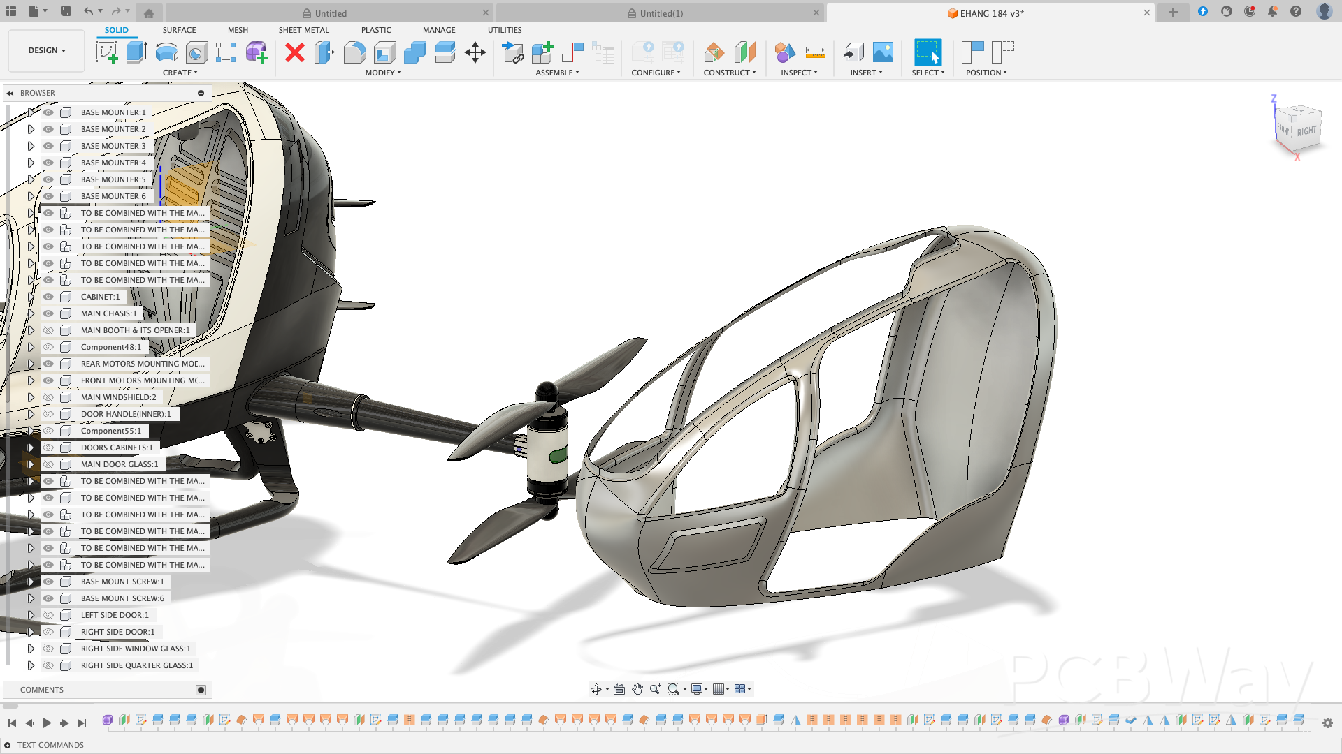
The base mount (suspension system) is designed as a two-part modular assembly to simplify printing, alignment, and installation.
. Right module: integrates the right-side landing gear along with the front and rear right arms.
. Left module: integrates the left-side landing gear along with the front and rear left arms.
These two modules are joined at the center using overlapping structural connectors, which provide accurate alignment and improved rigidity. In the rendered image, these connectors are easily identifiable as the dark-black interlocking structures with mounting holes located at the center of the assembly.
This split-assembly approach improves:
. Printability on smaller 3D printers
. Structural strength after assembly
. Ease of maintenance and part replacement
Please refer to the image above to clearly identify the overlapping connection features and mounting points.
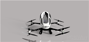
Landing Gears and Base Mount (Suspension) Assembly
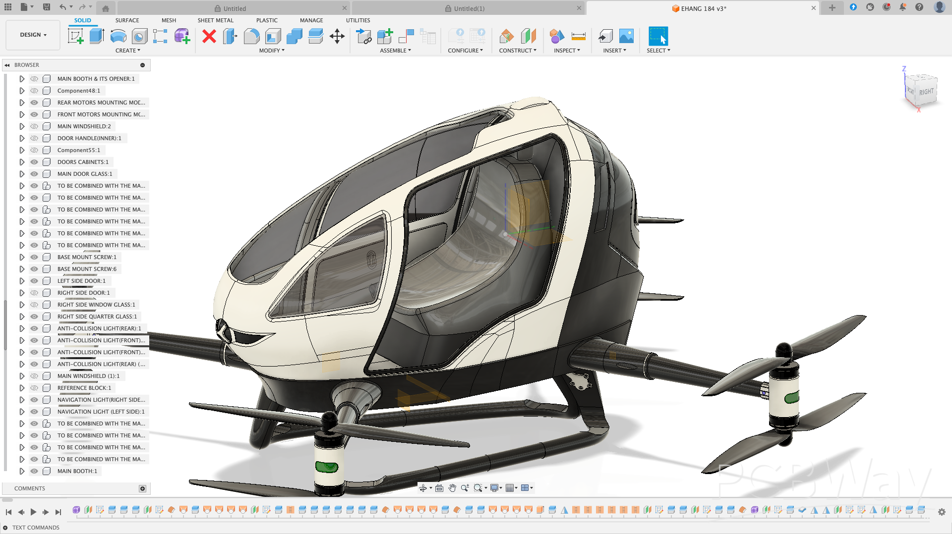
If you examine the second rendered image closely, you will notice that each landing gear is securely attached to the base mount using gray structural support brackets. These brackets extend from the lower end of each landing gear directly into the base mount, providing both mechanical strength and stability.
Each support bracket features four mounting holes, which align with corresponding holes on the landing gear. This mounting method ensures:
. Firm load transfer from the landing gear to the base mount
. Improved impact resistance during landing
. Easy assembly and disassembly for maintenance or customization
The use of separate support brackets also makes the suspension system modular and beginner-friendly, allowing individual landing gears to be replaced or modified without affecting the entire base mount.
Base Mount and Main Chassis Assembly
In the first rendered image, you will notice several V-shaped mounting brackets, shown in gray, attached to the base mount. These brackets serve as the mechanical interface between the suspension system (base mount) and the main chassis.
The V-shaped geometry is intentional:
. It improves structural rigidity
. Distributes load evenly between the chassis and suspension
. Enhances impact resistance during landing
The main chassis is secured to these mounting brackets using standard screws, creating a strong and reliable connection.
Assembly Tip
To assemble correctly, insert each base mount half (left and right) into the corresponding mounting holes in the main chassis. These holes are clearly visible in the main chassis image shown below. Once aligned, fasten the V-shaped brackets with screws to lock the chassis firmly onto the suspension assembly.
This mounting approach keeps the structure modular, easy to assemble, and easy to service, making it ideal for educational, experimental, and customizable drone builds.

In total, the main chassis features 10 rectangular mounting slots, with 5 slots on each side. These slots are designed to receive the left and right base mount assemblies, ensuring precise alignment and a secure mechanical fit.
Once the base mounts are inserted into their respective rectangular slots, the main chassis sits firmly on the suspension system. This interlocking design improves structural stability and simplifies the assembly process.
Below is the rendered screenshot showing the main chassis fully mounted onto the base mount (suspension), illustrating the final alignment and overall structural integrity of the assembly.
The same assembly technique applies to the booth.
The booth is designed with corresponding mounting features that align with the main chassis slots and support structures. Once positioned correctly, it slides into place and is secured using the same screw-based fastening method used throughout the frame.
This approach ensures:
. Proper alignment without guesswork
. Structural rigidity after installation
. Easy removal for maintenance or future customization
. A consistent, beginner-friendly assembly process
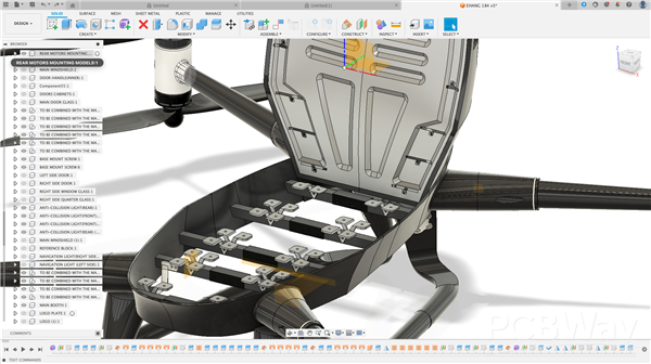
The Drone’s Arms and Base Mount Assembly
Refer to the screenshot below to see exactly where the right rear arm mounts to the base mount (suspension).
This visual reference is important because correct arm placement directly affects:
. Motor alignment
. Frame symmetry
. Flight stability
As the saying goes, “seeing is believing.” The image clearly shows the arm orientation, mounting interface, and screw locations, making the assembly process easy to follow—especially for beginners.
Mounting the Drone’s Arms
Mount each arm to the base mount using screws. As shown in the screenshot, each arm has two clearly marked screw holes.
. Apply the same process for all remaining arms.
. This ensures proper alignment, structural stability, and balanced flight performance.
With this, you now have a basic understanding of the frame assembly.
Next, let’s take a look at the interior layout of the drone to see where all electronics fit.
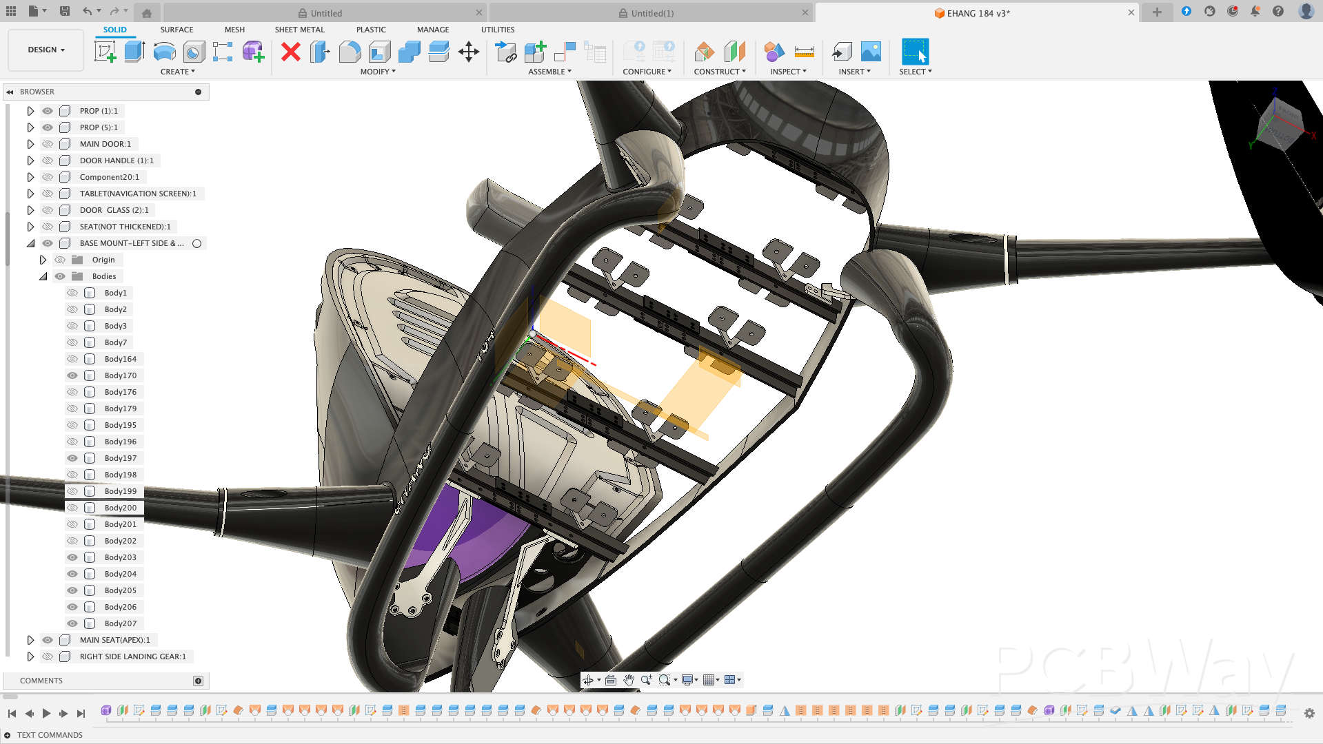
Interior Booth and Customizable Parts
Take a close look at the interior of the drone—you’ll notice the seat module, belt molding, and other components.
. Every part in this project is fully customizable.
. Feel free to modify or adapt these parts to suit your own design preferences.
Below is an image showing how the booth was designed in this project.
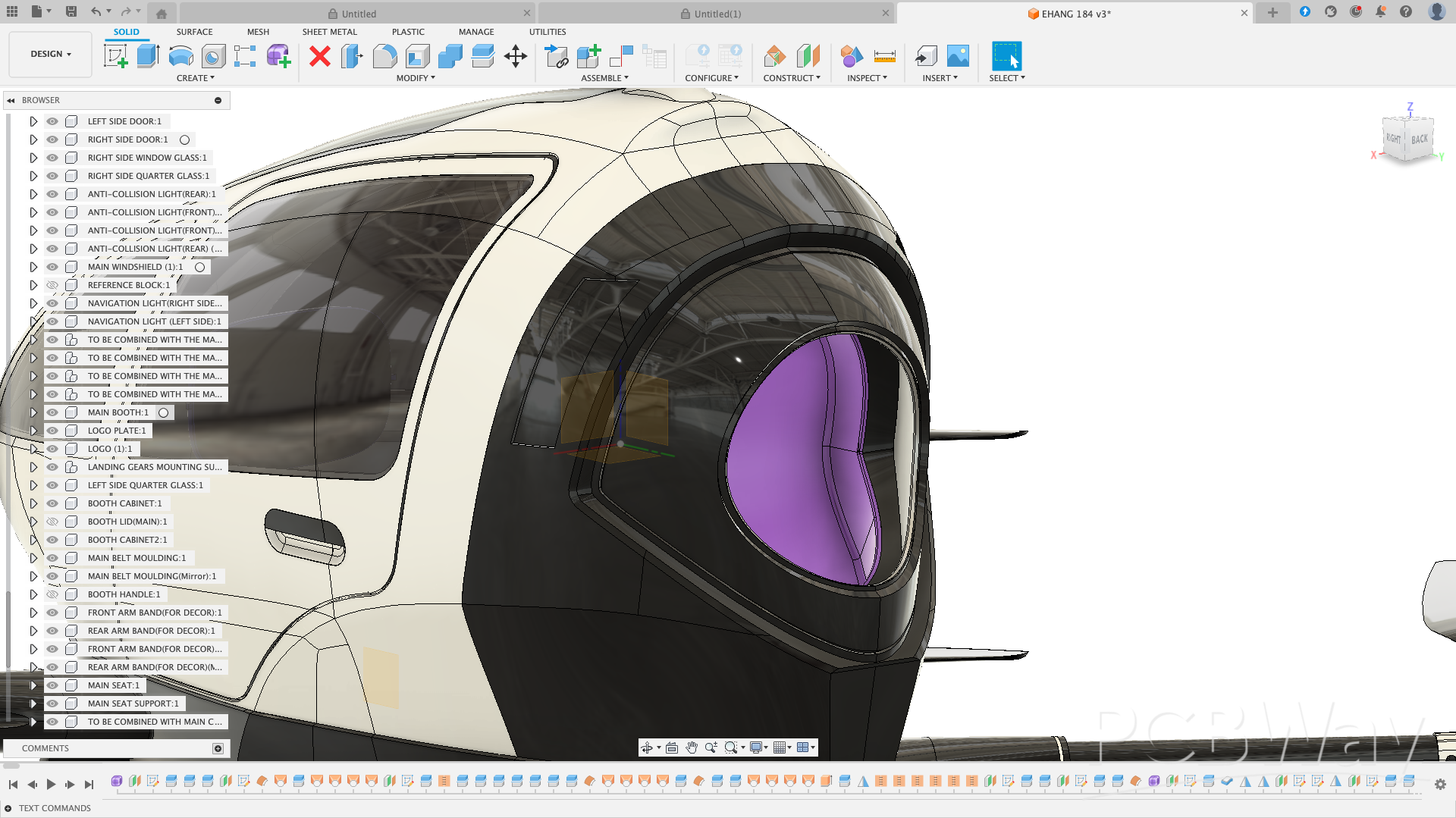
Interior Cabin Showcase
Looks pretty nice, right? Take a close look at the cabin (interior cabin) in the screenshot below.
. The cabin layout is clean, detailed, and easy to customize.
. Every element—from seats to panels—can be adapted to your own design preferences.
Below is the screenshot showing the cabin layout in this project.
Section it according to how you want to section it and design your lockings and apply your thickness. Simple as A, B, C.
Conclusion
In conclusion, all the screenshots above provide a clear, step-by-step guide for assembling the drone, saving you months of trial-and-error. They also highlight the design originality of this project, which will be appreciated by PCBWAY judges.
This project is intended as a flexible, educational platform:
. Intermediate & Advanced Users: Explore CAD modeling, modify structural components, and create your own unique version of the EHANG 184 drone.
. Beginners: Follow the above YouTube tutorials where I demonstrated design techniques, modeling tips, and shortcuts used in this project to help you understand the modeling workflow and start customizing safely.
Most parts were thickened and optimized for 3D printing, while some - such as the main chassis and locking joints - were intentionally left unthickened to allow easy customization for different print materials or assembly preferences.
This ensures flexibility for anyone who wants to build, modify, or integrate their own mechanical components.
Design Intent
The purpose of this design is to showcase the power of Fusion 360 for precise mechanical geometry, functional details, and creative design presentation.
Although this current version focuses on the mechanical structure only, it is fully ready for the addition of electronics such as:
. Pixhawk 6X or similar flight controller,
. Motors, ESCs, and propellers,
. Lighting and sensor systems.
These will be added in future updates to complete the working version.
Tools Used
. Autodesk Fusion 360 - for 3D modeling, visualization, and rendering.
About the Designer
I'm Kamal Deen, a self - taught 3D designer from Ghana.
I specialized in drone, vehicle, and mechanical designs using Fusion 360 - creating detailed models that bridge imagination and engineering.
I enjoy transforming real - world innovations into 3D concepts that inspire creativity, education, and future manufacturing.
Contact: mohammedkamaldeen2424@gmail.com
Contest Entry
This project is my official submission for the PCBWAY 8th Project Design Contest (Mechanical), representing a vision of advanced aerial design made accessible through 3D modeling and creativity.
"Full STL assembly available upon request due to file size limits"
. Encouragement: Feel free to thicken parts, add locking mechanisms, redesign mounting systems, or tweak any element to suit your project requirements. The drone is intentionally left modular to support creativity, learning, and experimentation.
Anyway, I hope this project has been helpful and inspiring for you!
Happy customizing!
EHANG 184 Fully Customizable 3D Drone Project – For Intermediate & Advanced CAD Users
Project images are for reference only. Actual production is based on the manufacturing files on the project page.
Please review the designer's notes (e.g., PCB thickness) and select the appropriate options.
PCBWay is not responsible
for issues caused by unsuitable parameter selections.
For more important ordering information, please refer to
Read More


Raspberry Pi 5 7 Inch Touch Screen IPS 1024x600 HD LCD HDMI-compatible Display for RPI 4B 3B+ OPI 5 AIDA64 PC Secondary Screen(Without Speaker)
BUY NOW


- Comments(4)
- Likes(2)
- 1 USER VOTES
- YOUR VOTE 0.00 0.00

-
5design
-
4usability
-
6creativity
-
6content
More by Engineer
-
 EHANG 184 Fully Customizable 3D Drone Project – For Intermediate & Advanced CAD Users
Project Overview This EHANG 184 drone model, inspired by EHANG, a leader in autonomous aerial vehicl...
EHANG 184 Fully Customizable 3D Drone Project – For Intermediate & Advanced CAD Users
Project Overview This EHANG 184 drone model, inspired by EHANG, a leader in autonomous aerial vehicl...
-
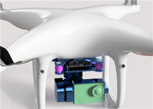 “Complete DJI Phantom 4 Replica Drone with Custom PCBs, LED System & Mechanical Design”
Project OverviewThis project is a full DJI Phantom 4–inspired drone design created for learning and ...
“Complete DJI Phantom 4 Replica Drone with Custom PCBs, LED System & Mechanical Design”
Project OverviewThis project is a full DJI Phantom 4–inspired drone design created for learning and ...
-
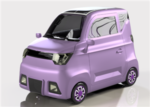 Ford Mini Solar Electric Car – TI MPPT & Libre Solar BMS Integration
project Intent / ObjectiveThe Ford Mini Solar Electric Car was conceived from my passion for sustain...
Ford Mini Solar Electric Car – TI MPPT & Libre Solar BMS Integration
project Intent / ObjectiveThe Ford Mini Solar Electric Car was conceived from my passion for sustain...
-
 DJI MINI PHANTOM 4 PRO
The name of the project is DJI MINI PHANTOM4 PRO.I designed this drone purposely for cinematography....
DJI MINI PHANTOM 4 PRO
The name of the project is DJI MINI PHANTOM4 PRO.I designed this drone purposely for cinematography....
-
Programmable Mist Maker - XIAO / QT PY Extension
1066 2 1 -
RadioHAT - Raspberry Pi radio development platform
879 0 2 -
-
-
-
-
ARPS-2 – Arduino-Compatible Robot Project Shield for Arduino UNO
3332 0 6 -
A Compact Charging Breakout Board For Waveshare ESP32-C3
3940 3 8 -
AI-driven LoRa & LLM-enabled Kiosk & Food Delivery System
4326 2 2


