


|
|
Pico2RaspberryPi
|
x 1 | |
|
|
MPU-6050 |
x 1 | |
|
|
Pico2(W) Add Board(Custom Board) |
x 1 |

|
Zephyr Project |
|

|
KiCADKicad
|
|

|
Edge Impulse Studio |
Zephyr(RTOS) Gesture Edge AI on Raspberry Pi Pico 2
This project presents a Zephyr Demo with Edge Impulse and Raspberry Pi Pico and Pico2(W)
Introduction
This project showcases examples of gesture recognition using external sensors with the Raspberry Pi Pico2(W).
We can build with the Zephyr(RTOS) and Edge AI models deployed from Edge Impulse.
Furthermore, the build and deployment process is fully compatible with the original Raspberry Pi Pico as well.

Overview and Demo Videos
This project main topics are as follows:
-Edge AI system with Zephyr(RTOS) and Pico2(W).
-Fits into much small(Kbytes Range) RAM and ROM.
-To train and deploy Edge Impulse onto Zephyr(RTOS).
Here are the demo videos showcasing the final results on YouTube:
-Cross-Platform(Pico and Pico2) Demo:
Demonstrates the Gesture AI running seamlessly on both Pico and Pico2 using Zephyr.
-Custom Hardware Test:
Shows the Gesture AI being tested on custom board, the "Pico 2(W) Add Board."
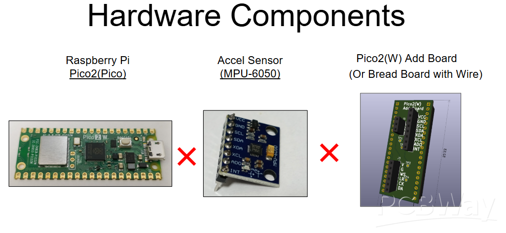
Hardware Design
This section details the core components. The system consists of the following three parts:
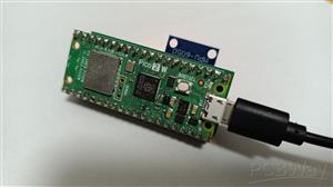
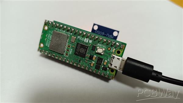
-Raspberry Pi Pico 2 / Pico 2 W
(Note: The original Pico/Pico W is also compatible.)
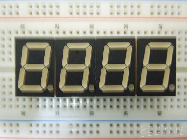
-Accel Sensor MPU-6050 Module
(A standard sensor module widely available on markets like eBay, Amazon, etc...)
https://www.ebay.com/itm/112088281224
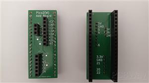
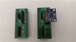
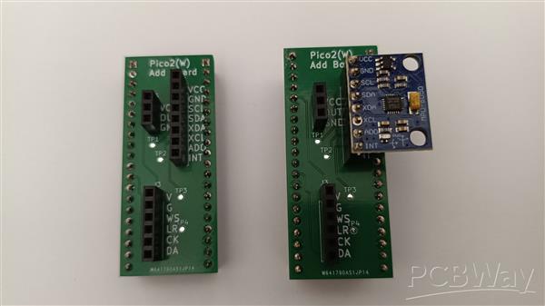
-Pico2(W) Add Board
(This is a custom board, but a breadboard and jumper wires can be used as a substitute.)
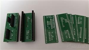
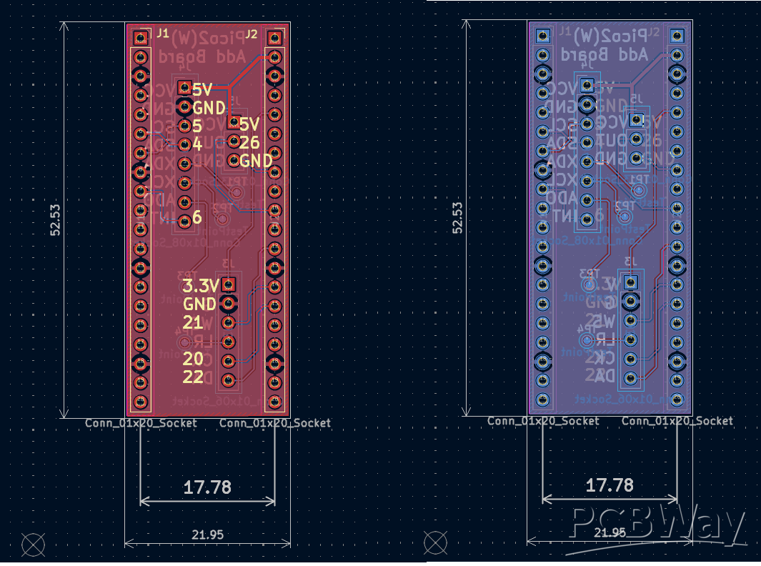
Custom Board
The custom board acts as a simple interface adapter, primarily routing signals via connectors.
It connects the Raspberry Pi Pico to the MPU-6050 accelerometer via I2C.
Please refer to the Schematic and BOM for further details.
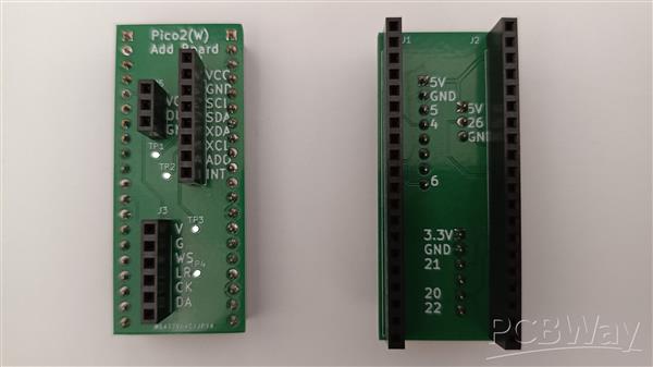
The pin configuration is shown below.
-Pico2(W) -Sensor (MPU-6050)
-39 (VSYS) -1 (VCC)
-38 (GND) -2 (GND)
-7 (I2C0 SCL) -3 (SCL)
-6 (I2C0 SDA) -4 (SDA)
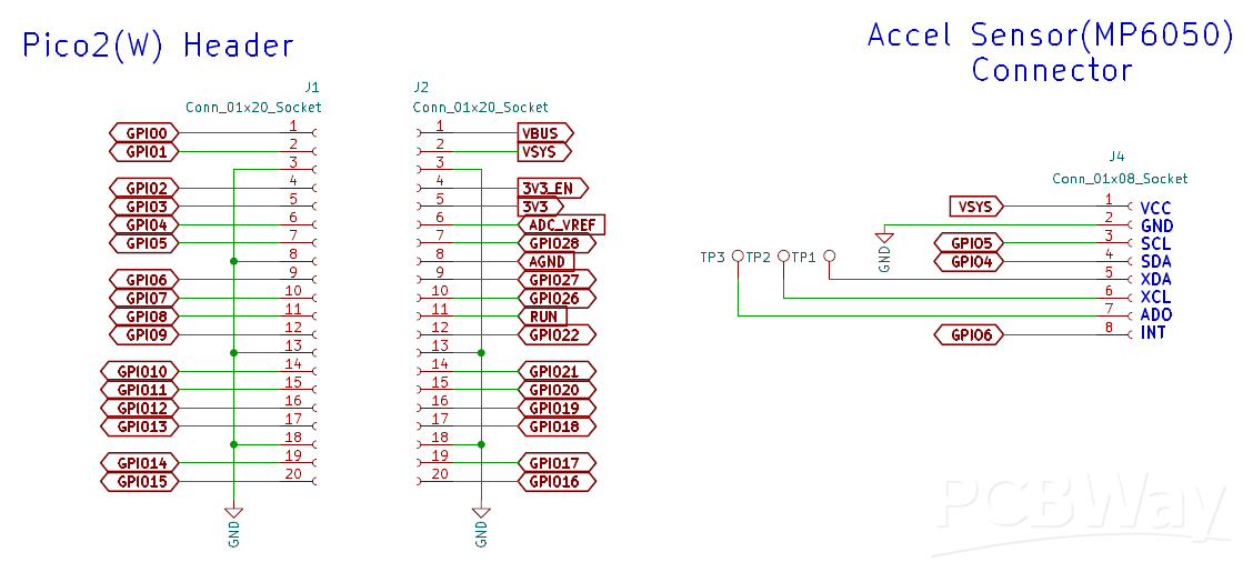
Note that while the board features three connectors, this project only utilizes the 8-pin connector (J4).
Software Design
Source code for this project are available on GitHub.
https://github.com/iotengineer22/pico2-ei-zephyr-demo
Note: Due to licensing restrictions, the Edge Impulse model cannot be provided directly.
You will need to create and download the model yourself.
The following section provides a step-by-step guide on the training and deployment process for your reference.
Data Acquisition with Edge Impulse
To train a machine learning model, the first step is acquiring data directly from the device.
We prepare demo video how to capture accelerometer values using Edge Impulse and Zephyr RTOS.
Please check it out.
Although this video demonstrates the connection between Pico2(W) and the sensor board using a breadboard, the custom Add Board works in exactly the same way.
We will capture accelerometer data by referring to the official documentation below:
https://docs.edgeimpulse.com/tools/clis/edge-impulse-cli/data-forwarder
System Overview:
We will use the Edge Impulse CLI Data Forwarder to capture data via USB Serial.
Firmware: Outputs sensor data to USB Serial.
CLI: Forwards that serial data to Edge Impulse Studio.
We have prepared a Zephyr program that continuously outputs x, y, and z accelerometer readings via I2C at 104Hz.
You can find the code here:
https://github.com/iotengineer22/pico2-ei-zephyr-demo/tree/main/src/pico2w/pico-imu_dataforwarder
I repeated the sampling process to collect the necessary training data.
For this project, I trained the model using four classes: idle, circle, updown, and flick.
The data is available on GitHub at the link below.
Please note that this is a rough sample dataset (about 1 minute long), so use it with that in mind.
https://github.com/iotengineer22/pico2-ei-zephyr-demo/tree/main/raw_data
Training with Edge Impulse
We will proceed with training by following the official sample below:
https://docs.edgeimpulse.com/datasets/time-series/continuous-motion-recognition
Edge Impulse Design:
-Time series data: Window size set to 2000ms (changed from 1000ms).
-Processing block: Spectral Analysis.
-Learning block: Classification, Anomaly Detection (K-means).
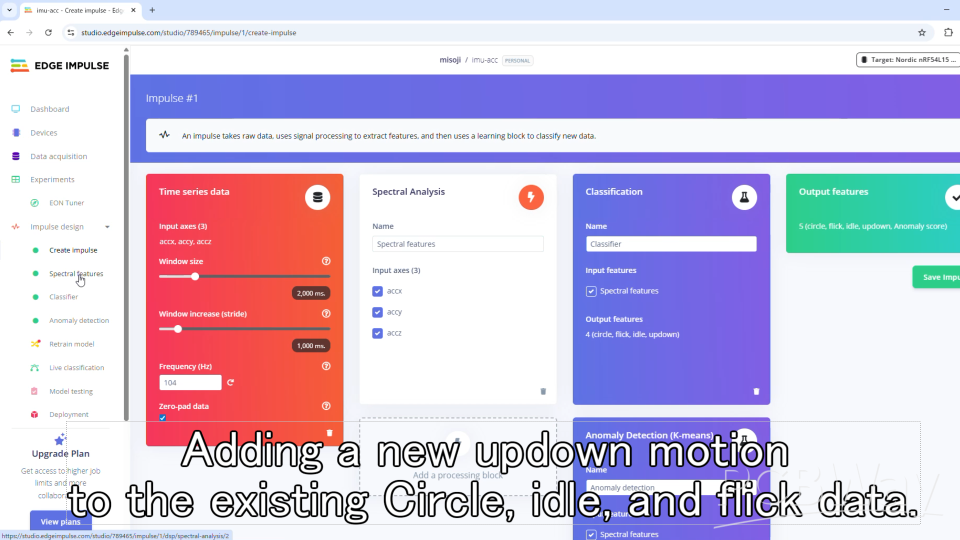
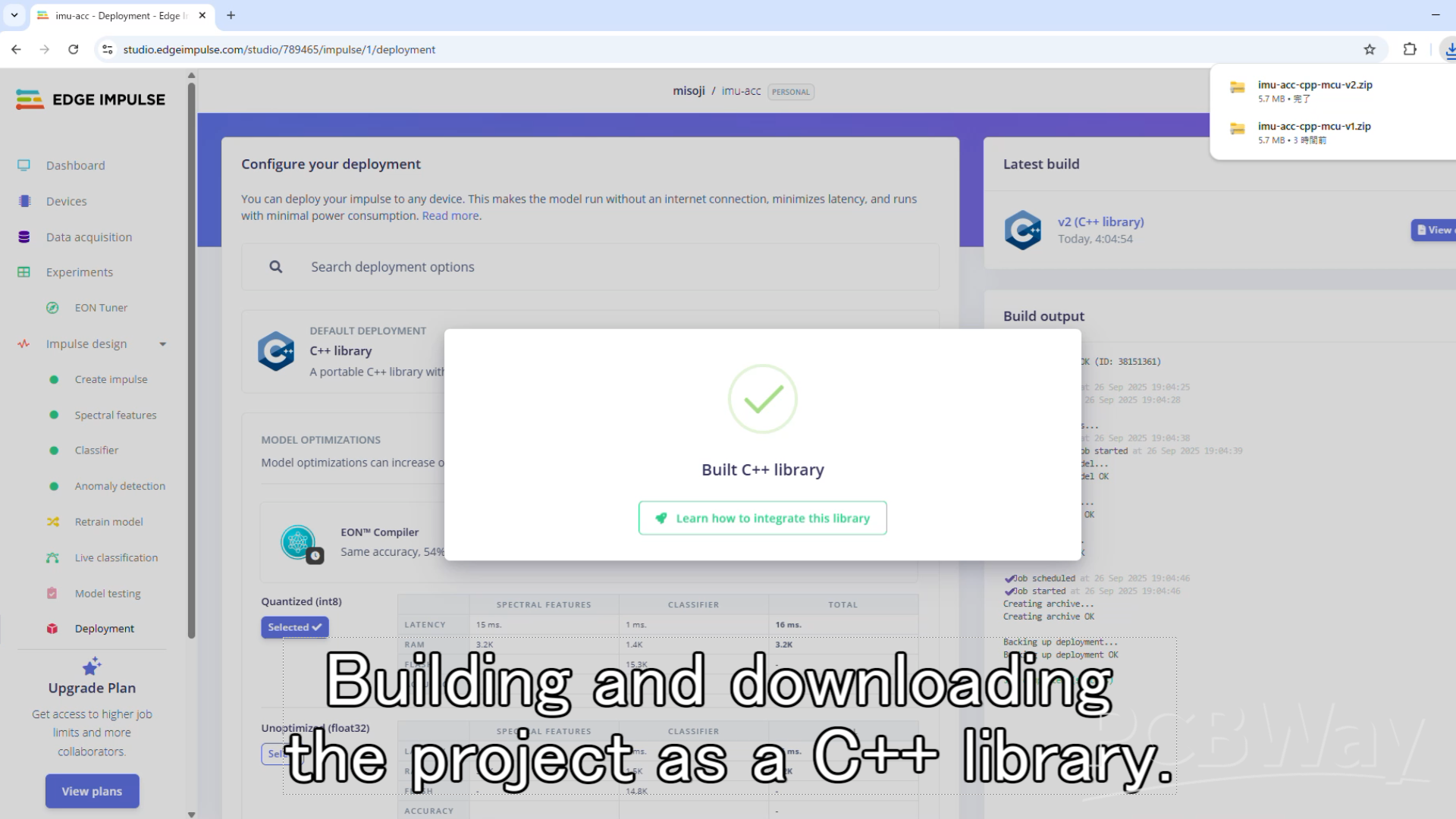
Finally, proceed to the Deployment section. Select C++ Library as the target and build the model.
Note: Although the following video does not use the Pico 2, it demonstrates the same training process with Edge Impulse using an accelerometer.
Please refer to it as a guide.
Build with Zephyr(RTOS)
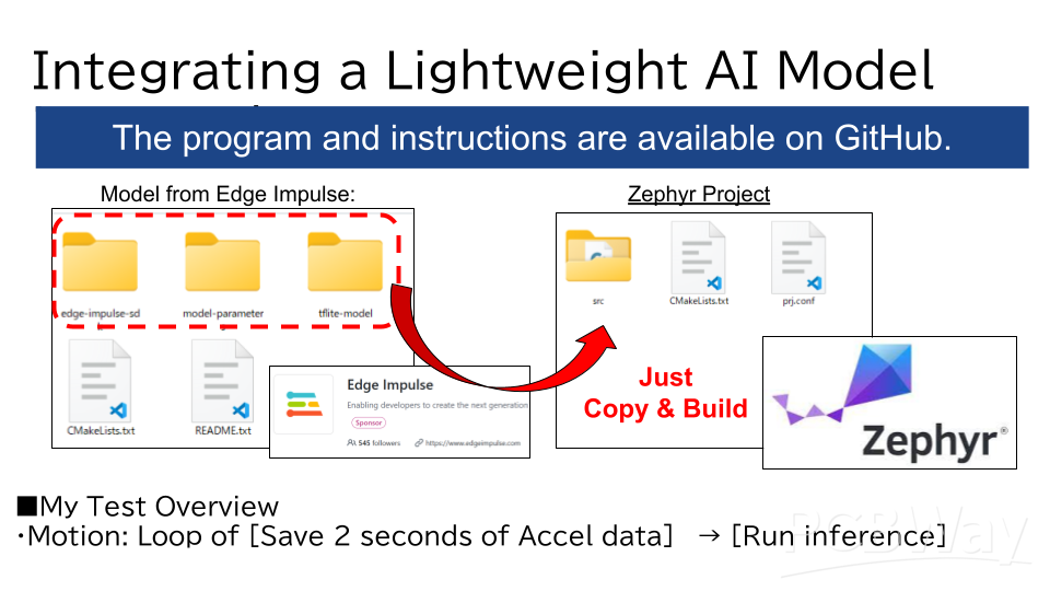
Upon checking the folder downloaded from Edge Impulse, you will find the C++ SDK, parameters, and model files.
Copy all the contents (the edge-impulse-sdk/, model-parameters/, and tflite-model/ directories) into the Zephyr project.
We will build the project on Zephyr RTOS by combining these files with the program linked below:
https://github.com/iotengineer22/pico2-ei-zephyr-demo/tree/main/src/pico2w/pico-imu_inference
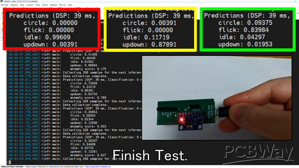
The application captures 2 seconds of data from a 3-axis accelerometer (X, Y, Z) at 104Hz.
It runs inference on the collected data to classify the gesture.
This process repeats in a continuous loop.
Open your terminal, navigate to the project directory, and run the standard Zephyr build and flash commands for your board.
For the Raspberry Pi Pico2(W) and , it would be:
west build -p -b rpi_pico2/rp2350a/m33/w
For the Raspberry Pi Pico and , it would be:
west build -p -b rpi_pico
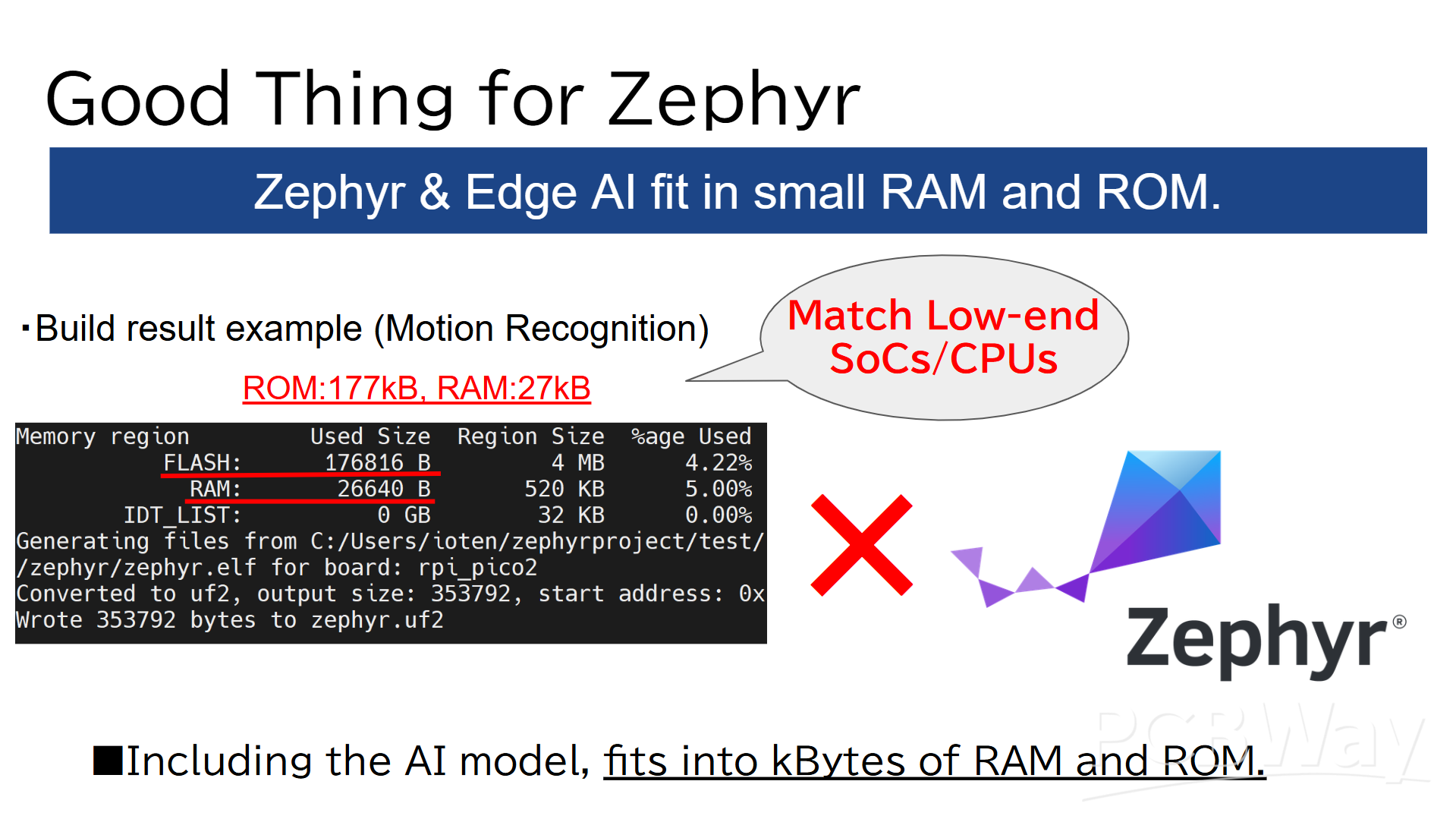
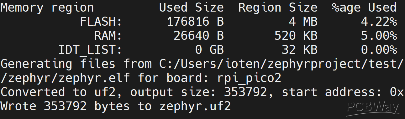
Here is the build result. As you can see, the RAM and ROM usage is extremely low(Kbytes Range).
ROM:177kB, RAM:27kB.
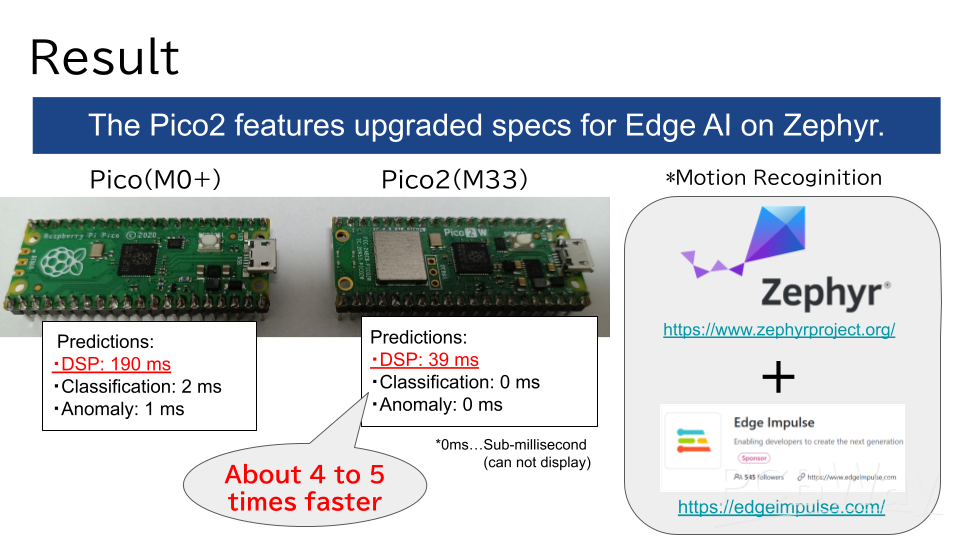
Pico and Pico2(W))
We flashed the firmware to both the Pico and Pico2(W) and conducted similar tests, starting with a breadboard setup.
While the Pico 2 (W) features many specification upgrades, the most significant difference is the inclusion of DSP extensions.
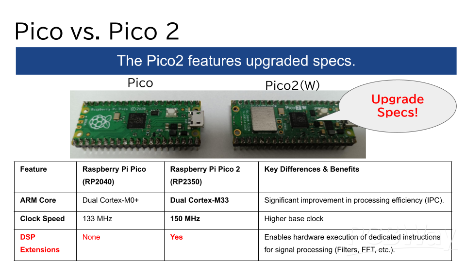
With Edge Impulse, these DSP extensions are automatically applied via CMSIS.
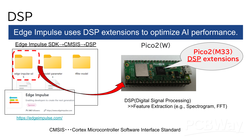
As a result, the processing speed for DSP operations is 4 to 5 times faster compared to the older Pico.
For more details, please refer to the demo video below (also introduced at the beginning).
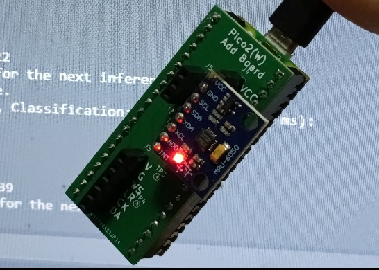
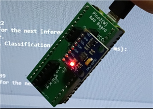
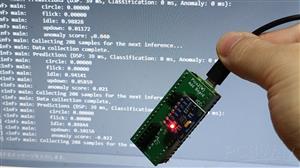
Custom Board Test
We also verified the operation using the custom board we created.
It successfully detects "Idle," "Updown," and "Flick" motions without any issues.
For more details, please refer to the demo video below (as mentioned at the beginning).
Conclusion
This project successfully achieved the following:
-Edge AI system with Zephyr(RTOS) and Pico2(W).
-Fits into much small(Kbytes Range) RAM and ROM.
-To train and deploy Edge Impulse onto Zephyr(RTOS).
This has been a great fun challenge.
Thanks to PCBWay.
Zephyr(RTOS) Gesture Edge AI on Raspberry Pi Pico 2
Project images are for reference only. Actual production is based on the manufacturing files on the project page.
Please review the designer's notes (e.g., PCB thickness) and select the appropriate options.
PCBWay is not responsible
for issues caused by unsuitable parameter selections.
For more important ordering information, please refer to
Read More


Raspberry Pi 5 7 Inch Touch Screen IPS 1024x600 HD LCD HDMI-compatible Display for RPI 4B 3B+ OPI 5 AIDA64 PC Secondary Screen(Without Speaker)
BUY NOW


- Comments(0)
- Likes(1)
More by misoji engineer
-
Programmable Mist Maker - XIAO / QT PY Extension
1060 2 1 -
RadioHAT - Raspberry Pi radio development platform
858 0 2 -
-
-
-
-
ARPS-2 – Arduino-Compatible Robot Project Shield for Arduino UNO
3320 0 6 -
A Compact Charging Breakout Board For Waveshare ESP32-C3
3926 3 8 -
AI-driven LoRa & LLM-enabled Kiosk & Food Delivery System
4314 2 2


