XRC PRO: Open-Source RC Transmitter and Receiver System
Overview
The XRC PRO is an advanced, open-source RC transmitter and receiver system designed to offer professional-level performance in a compact and customizable package. Built around the STM32F103C8T6 microcontroller and the NRF24L01 wireless transceiver module, the XRC PRO provides precise, real-time control for various RC applications like drones, cars, and boats. With a compact design, robust functionality, and user-friendly interface, the XRC PRO is an ideal tool for both hobbyists and professionals.
Key Features:
- OLED Display: Shows real-time signal strength, settings, battery percentage, and control data for easy monitoring.
- Trim Buttons & Rotary Encoder: Provides fine-tuned control and simple menu navigation, enhancing usability.
- Multi-Menus: Features an intuitive menu system for adjusting channel settings, polarity, and output modes.
- PPM & SBUS Outputs: Offers versatile output options, supporting a range of RC receivers for greater functionality.
- NRF24L01 Power Control: Includes adjustable signal strength settings, allowing for both short- and long-range control.
- Stick Calibration: Enables real-time stick calibration with visual feedback on the OLED display for precise adjustments.
- Compact Receivers: Offers two efficient receiver options for 8-channel PWM+PPM and PPM+SBUS outputs, designed for optimal performance.
- Throttle Mode: Allows selection between left or right throttle hand mode to suit user preferences.
- PC Simulator Compatibility: Supports computer-based simulators through PPM output, with an option to toggle PPM output on or off.
- Express ELRS Integration: Compatible with ELRS modules via PPM output when used with an ELRS adapter.
- Buzzer On/Off Mode: Enables users to easily toggle the buzzer for audio feedback during operation.
- Adjustable Setting Unit: Allows customization of measurement units (e.g., degrees, percentages) based on user preference.
- Battery Voltage Calibration: Calibrate battery voltage display for accurate percentage readings, ensuring reliable battery monitoring.
- Reset to Default Settings: Provides an option to restore all settings to default quickly for easy setup and troubleshooting.
Tech Specs
Microcontroller: STM32F103C8T6 ARM® Cortex®-M3
- ARM® Cortex®-M3 core up to 72 MHz
- 20KB onboard SRAM
- 64KB Flash memory
Wireless Module: NRF24L01 GT24 Mini
- Operates on 2.4 GHz ISM band
- High data rate up to 2 Mbps
- Supports multiple data pipes for communication
Display: 0.96" OLED
- Displays signal strength, battery percentage, and control data
Power: AMS117 3.3V Regulator
- Input voltage range from 7.4V to 12V (supports 2S to 3S LiPo batteries)
Weight: 200g (excluding battery)
Dimensions: 160 mm x 120 mm x 40 mm (excluding antenna)
Enclosure: DJI Phantom 2 Remote (customizable based on user preference; Arduino joysticks can be used as an alternative)
Transmitter Components
1.STM32F103C8T6: ARM microcontroller, desoldered from development board and soldered to transmitter PCB – Quantity: 1
Click to Buy: https://bit.ly/3ODReqC
2.NRF24L01 GT24 Mini: Wireless Transceiver Module – Quantity: 1
Click to Buy: https://bit.ly/3HTMQA0
2.E11 Rotary Encoder (ENC): Rotary encoder for menu navigation – Quantity: 1
Click to Buy: https://bit.ly/3UDggKq
3.SMD 8MHz Crystal (3225): Oscillator for STM32 – Quantity: 1
Click to Buy: https://shorturl.at/Ym75q
4.FC-135 32.768kHz Crystal: RTC crystal – Quantity: 1
Click to Buy: https://shorturl.at/v2CL1
5.CH340C SMD: USB to Serial Converter – Quantity: 1
Click to Buy: https://shorturl.at/4vJuk
6.Y1 (8050) NPN Transistor: General-purpose transistor – Quantity: 2
Click to Buy: https://n9.cl/b6pnc
7.1AM (3904) NPN Transistor: General-purpose transistor – Quantity: 1
Click to Buy: https://shorturl.at/Fs6E6
8.0.96" OLED Display: For displaying transmitter status and menu – Quantity: 1
Click to Buy: https://bit.ly/49arquy
9.10k Ohm Resistor (SMD): Resistor for various circuits – Quantity: 4
Click to Buy: https://bit.ly/3SAMR0D
10.1k Ohm Resistor (SMD): Resistor for various circuits – Quantity: 4
Click to Buy: https://bit.ly/3SAMR0D
11.100nF Capacitor (SMD): Signal filtering capacitor – Quantity: 20
Click to Buy: https://bit.ly/3ODT22S
12.Buzzer: Audio feedback for transmitter alerts – Quantity: 1
Click to Buy: https://bit.ly/3uru93D
13.AMS117 (3.3V Voltage Regulator): Provides 3.3V to components – Quantity: 1
Click to Buy: https://bit.ly/497yk3N
14.10uF Capacitor: Power stabilization and filtering – Quantity: 2
Click to Buy: https://bit.ly/3SzbI4Y
15.Male Headers: Connector for modules/components – Quantity: 30
Click to Buy: https://bit.ly/3uxOzrJ
16.DJI Phantom 2 Remote: Used as the transmitter enclosure; alternatives include any compatible remote/joystick.
Receiver Components
Receiver (PWM+PPM)
1.STM32F103C8T6: ARM microcontroller, desoldered from development board and soldered to receiver PCB – Quantity: 1
Click to Buy: https://bit.ly/3ODReqC
2.NRF24L01 GT24 Mini: Wireless Transceiver Module – Quantity: 1
Click to Buy: https://bit.ly/3HTMQA0
3.SMD 8MHz Crystal (3225): Oscillator for STM32 – Quantity: 1
Click to Buy: https://shorturl.at/Ym75q
4.1AM (3904) NPN Transistor: General-purpose transistor – Quantity: 1
Click to Buy: https://shorturl.at/Fs6E6
5.AMS117 (3.3V Voltage Regulator): Provides 3.3V to components – Quantity: 1
Click to Buy: https://shorturl.at/q2WBb
6.10uF Capacitor: Power stabilization and filtering – Quantity: 2
Click to Buy: https://bit.ly/3SzbI4Y
7.100nF Capacitor (SMD): Signal filtering capacitor – Quantity: 4
Click to Buy: https://bit.ly/3ODT22S
8.Male Headers: Connector for modules/components – Quantity: 30
Click to Buy: https://bit.ly/3uxOzrJ
Receiver (PPM+SBUS)
1.STM32F103C8T6: ARM microcontroller, desoldered from development board and soldered to receiver PCB – Quantity: 1
Click to Buy: https://bit.ly/3ODReqC
2.NRF24L01 GT24 Mini: Wireless Transceiver Module – Quantity: 1
Click to Buy: https://bit.ly/3HTMQA0
3.SMD 8MHz Crystal (3225): Oscillator for STM32 – Quantity: 1
Click to Buy: https://shorturl.at/Ym75q
4.1AM (3904) NPN Transistor: General-purpose transistor – Quantity: 1
Click to Buy: https://shorturl.at/Fs6E6
5.AMS117 (3.3V Voltage Regulator): Provides 3.3V to components – Quantity: 1
Click to Buy: https://shorturl.at/q2WBb
6.10uF Capacitor: Power stabilization and filtering – Quantity: 2
Click to Buy: https://bit.ly/3SzbI4Y
7.100nF Capacitor (SMD): Signal filtering capacitor – Quantity: 4
Click to Buy: https://bit.ly/3ODT22S
8.Male Headers: Connector for modules/components – Quantity: 30
Click to Buy: https://bit.ly/3uxOzrJ
Schematic and PCB Layout
The XRC PRO has multiple PCBs and it consists of three main PCBs: the Transmitter PCB, the 8-channel PWM+PPM Receiver PCB, and the PPM+SBUS Receiver PCB. Each PCB was carefully designed for space efficiency and optimal performance.
Transmitter PCBs
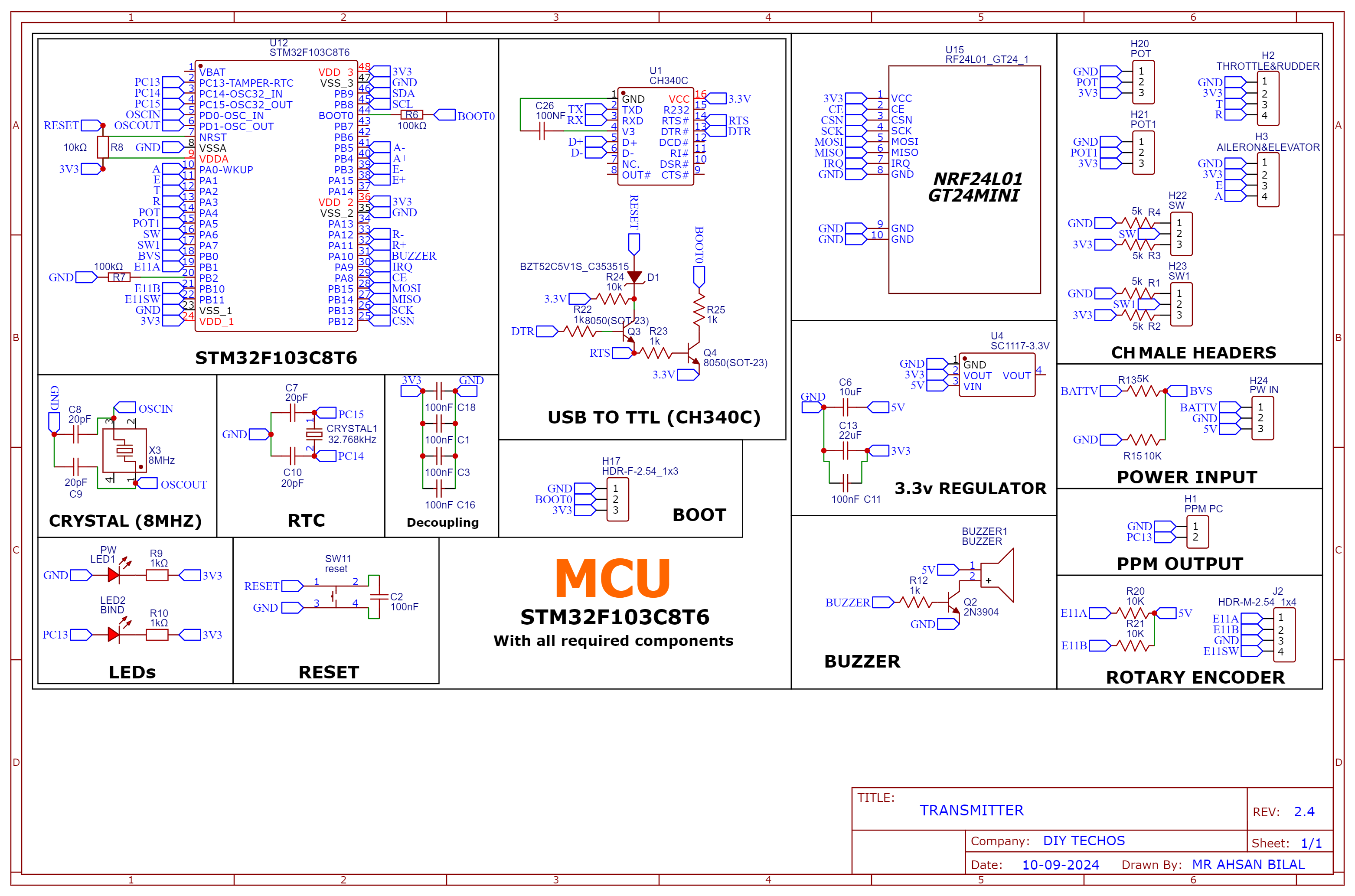
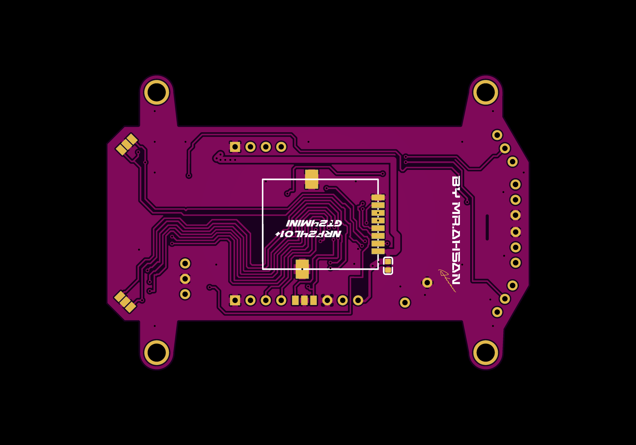
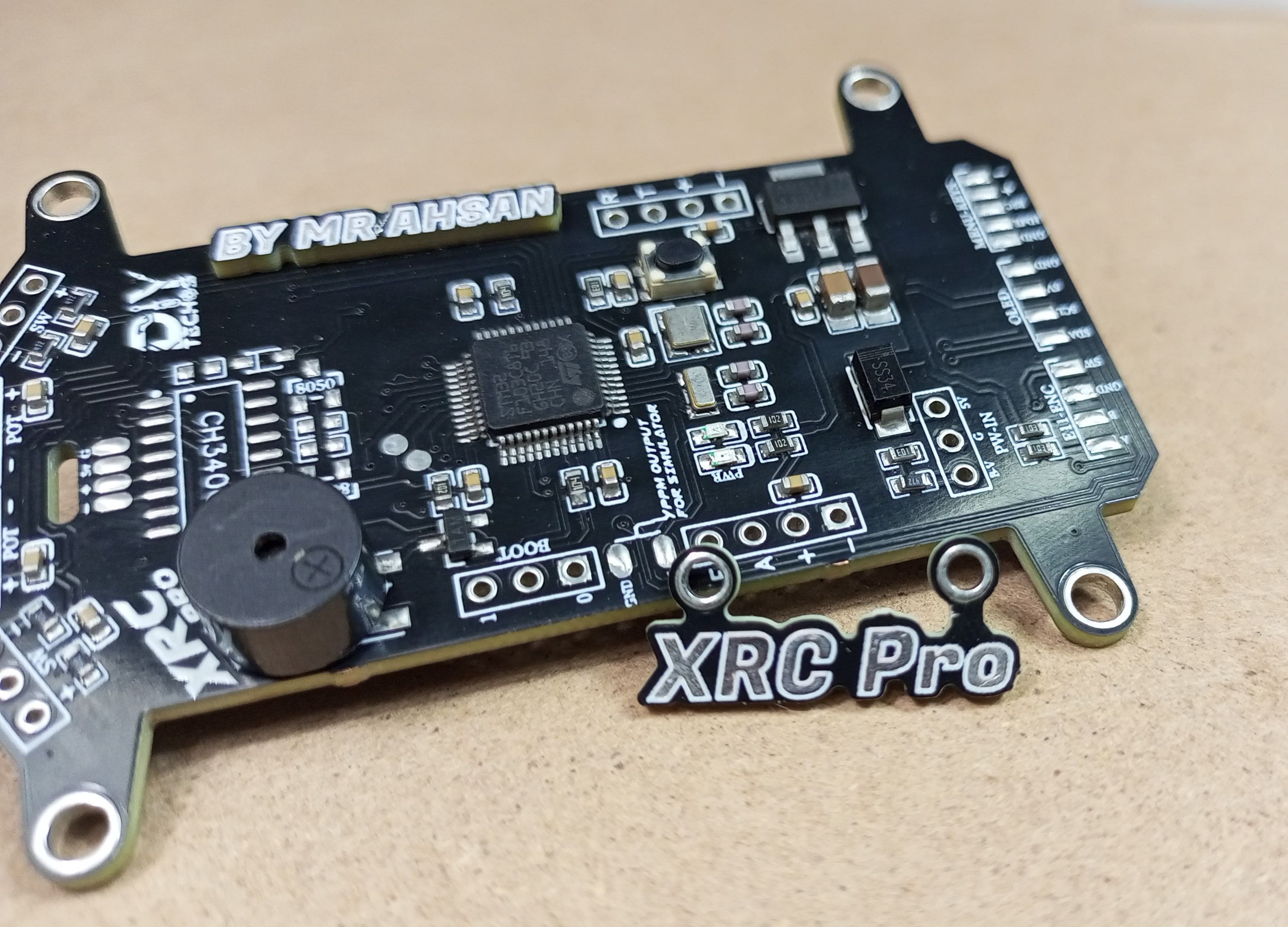
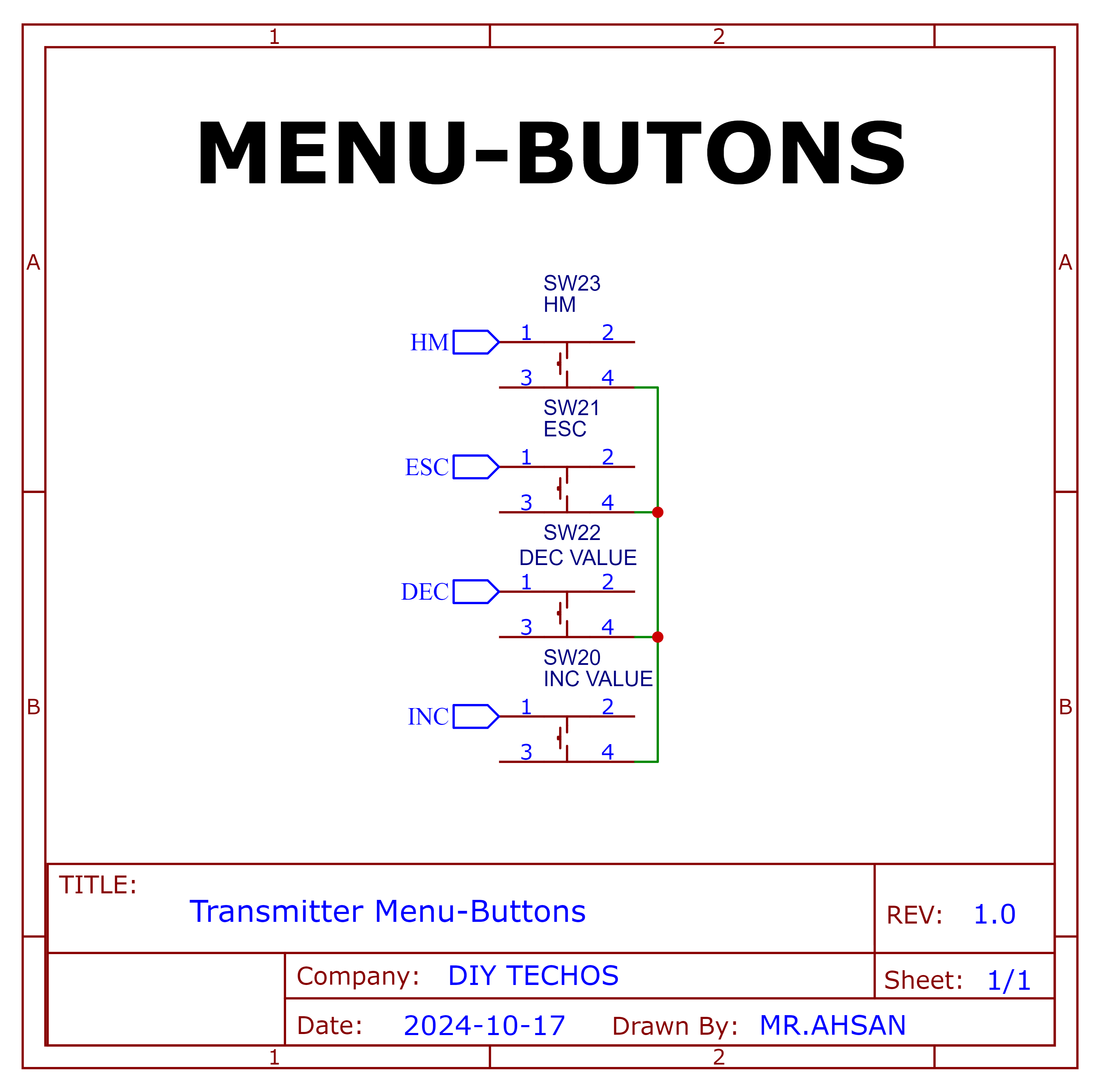
The Transmitter PCB is built around the STM32F103C8T6, NRF24L01 module, OLED display, and various input buttons (trim, menu, encoder). The schematic includes connections for power management (5v to 3.3v), data lines for the OLED, and button inputs for settings navigation etc.
Schematic and PCB Layout
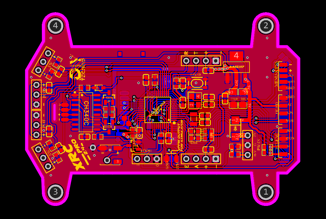
2D and 3D Preview
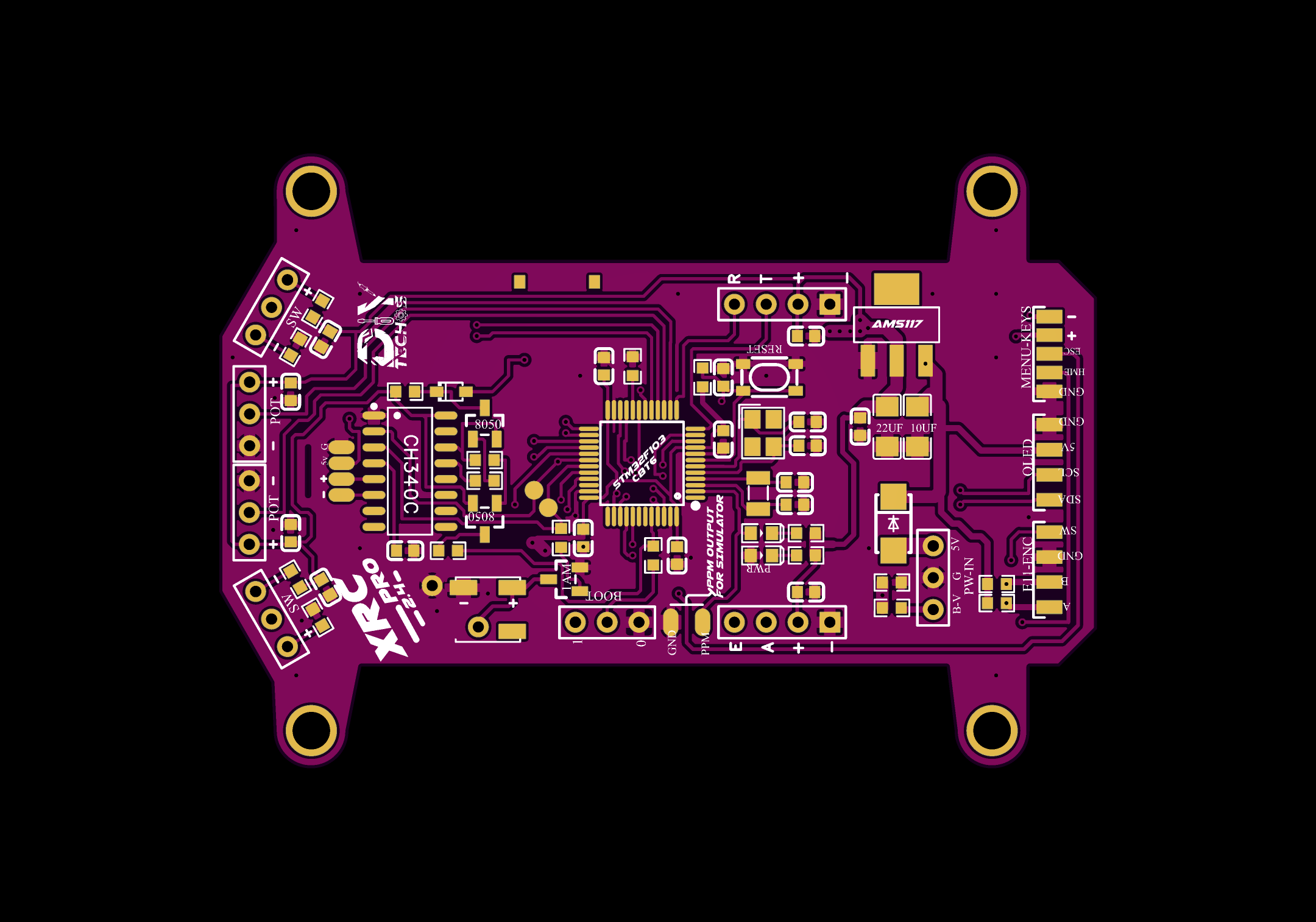


Final Result

Menu-Keys
Schematic and PCB Layout
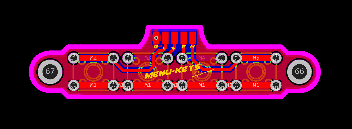
2D and 3D Preview


Final Result
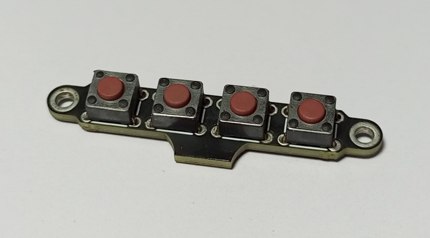
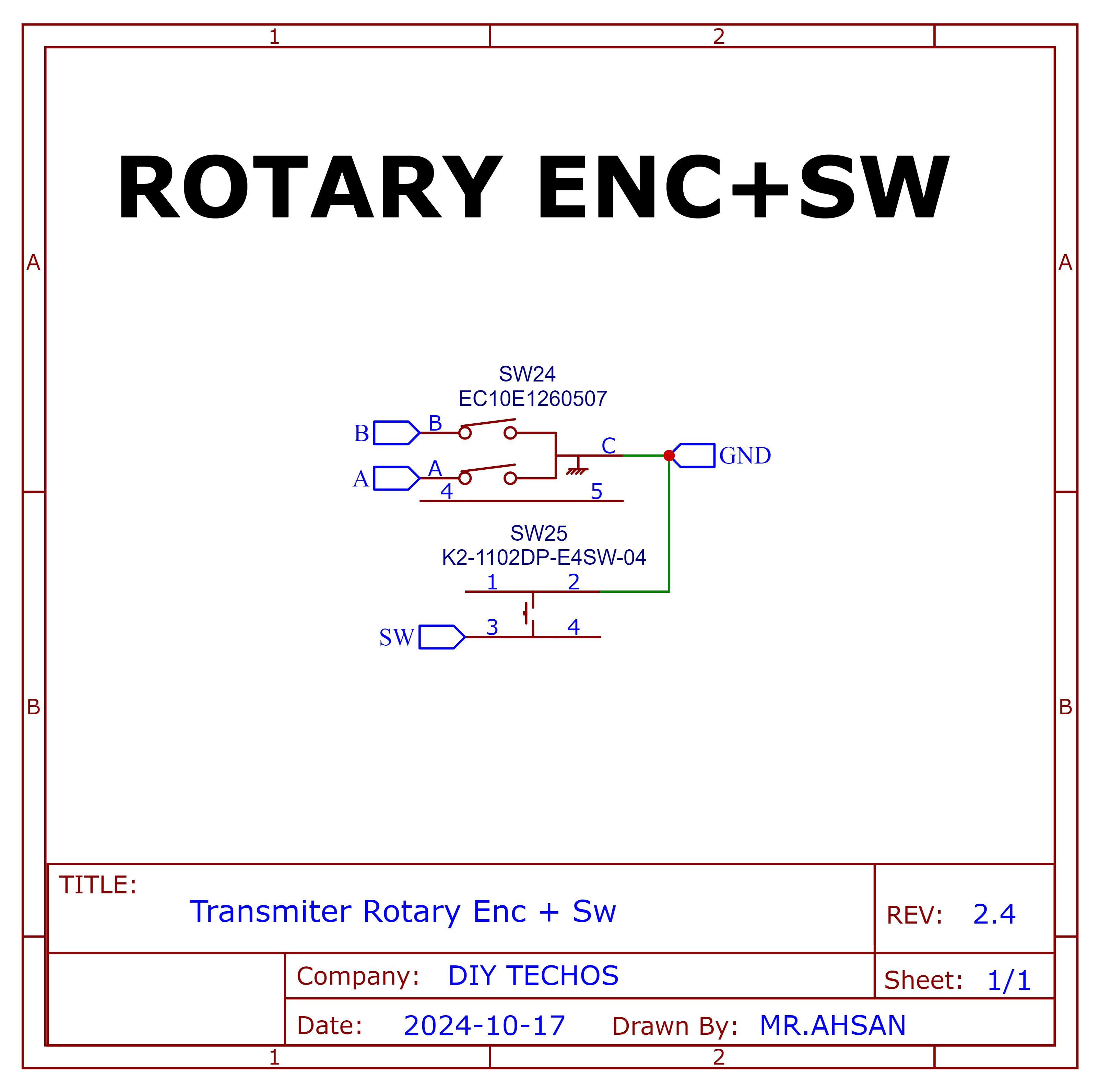
Rotary Encoder+Switch
Schematic and PCB Layout
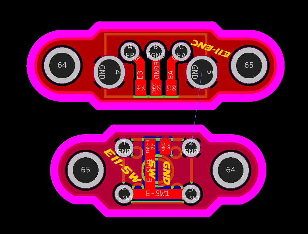
2D and 3D Preview
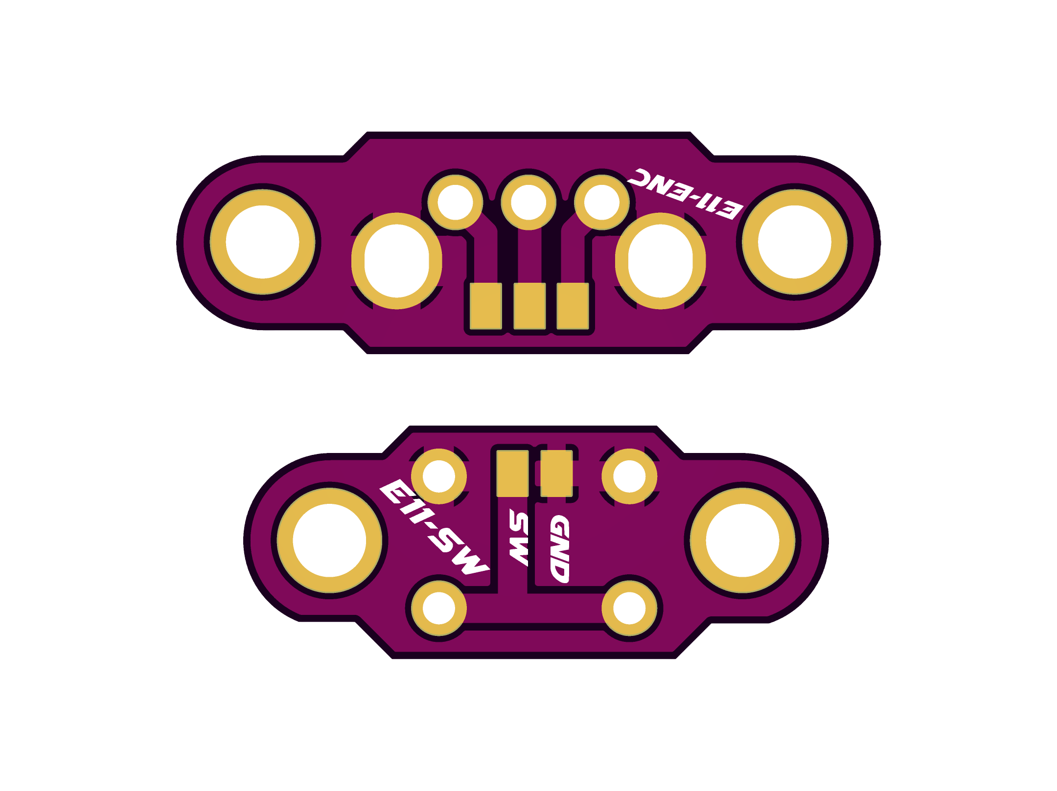


Final Result
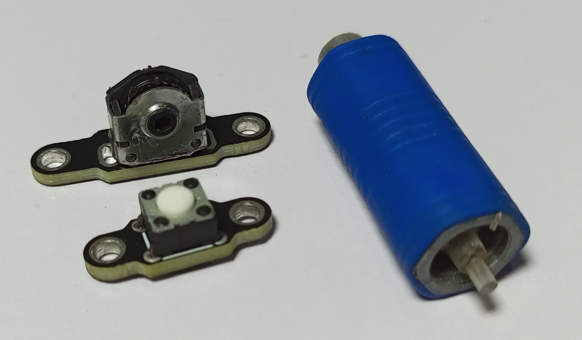
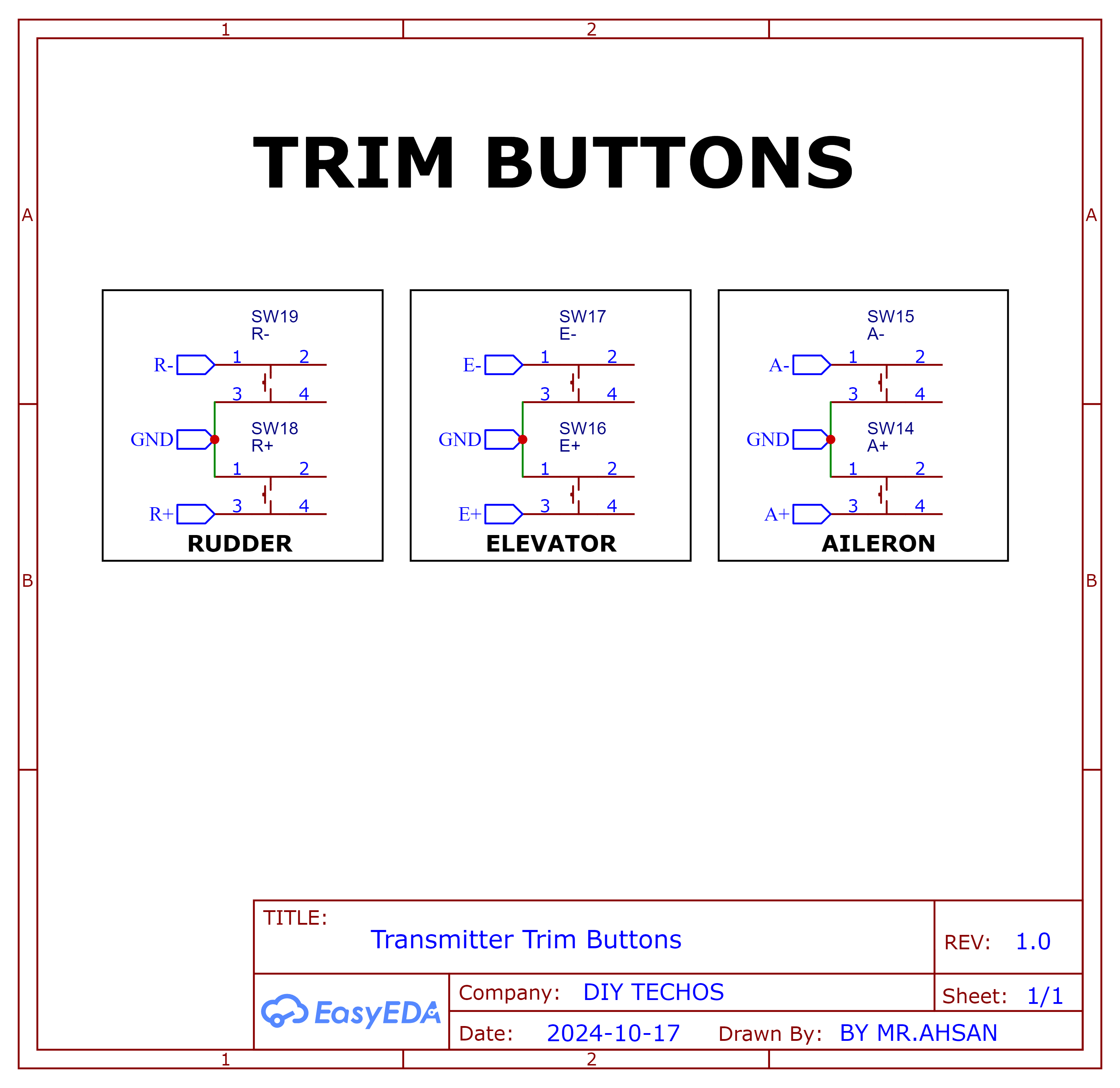
Trim Buttons
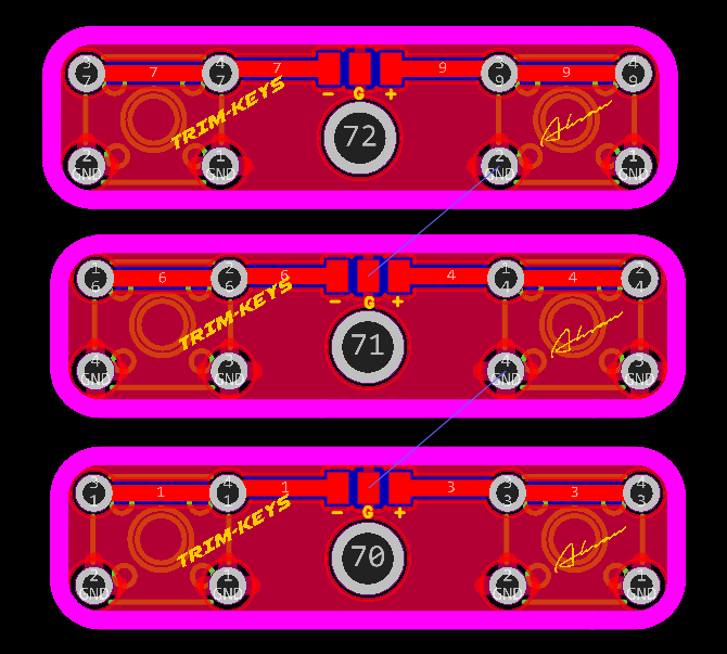
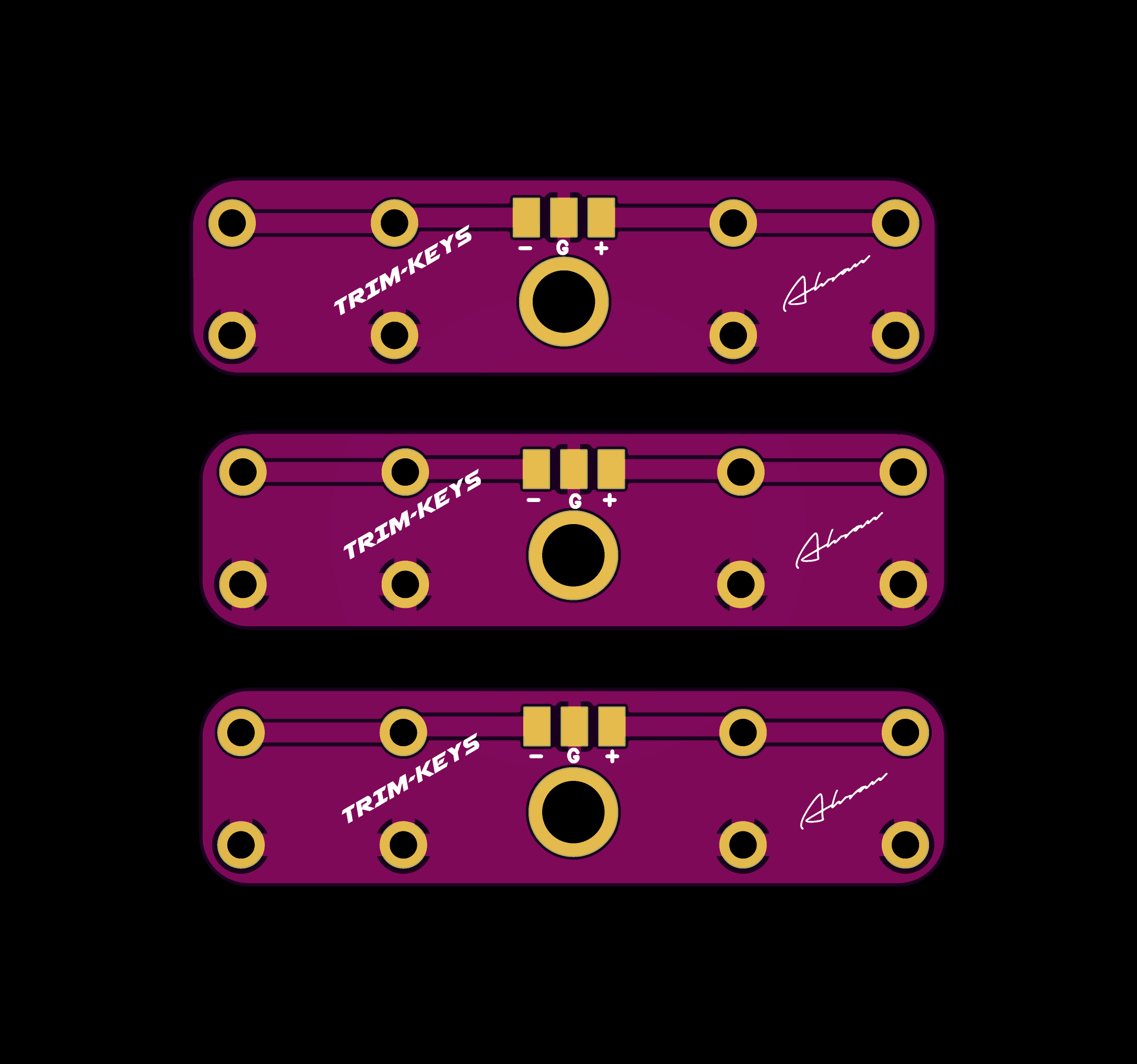
2D and 3D Preview


Final Result
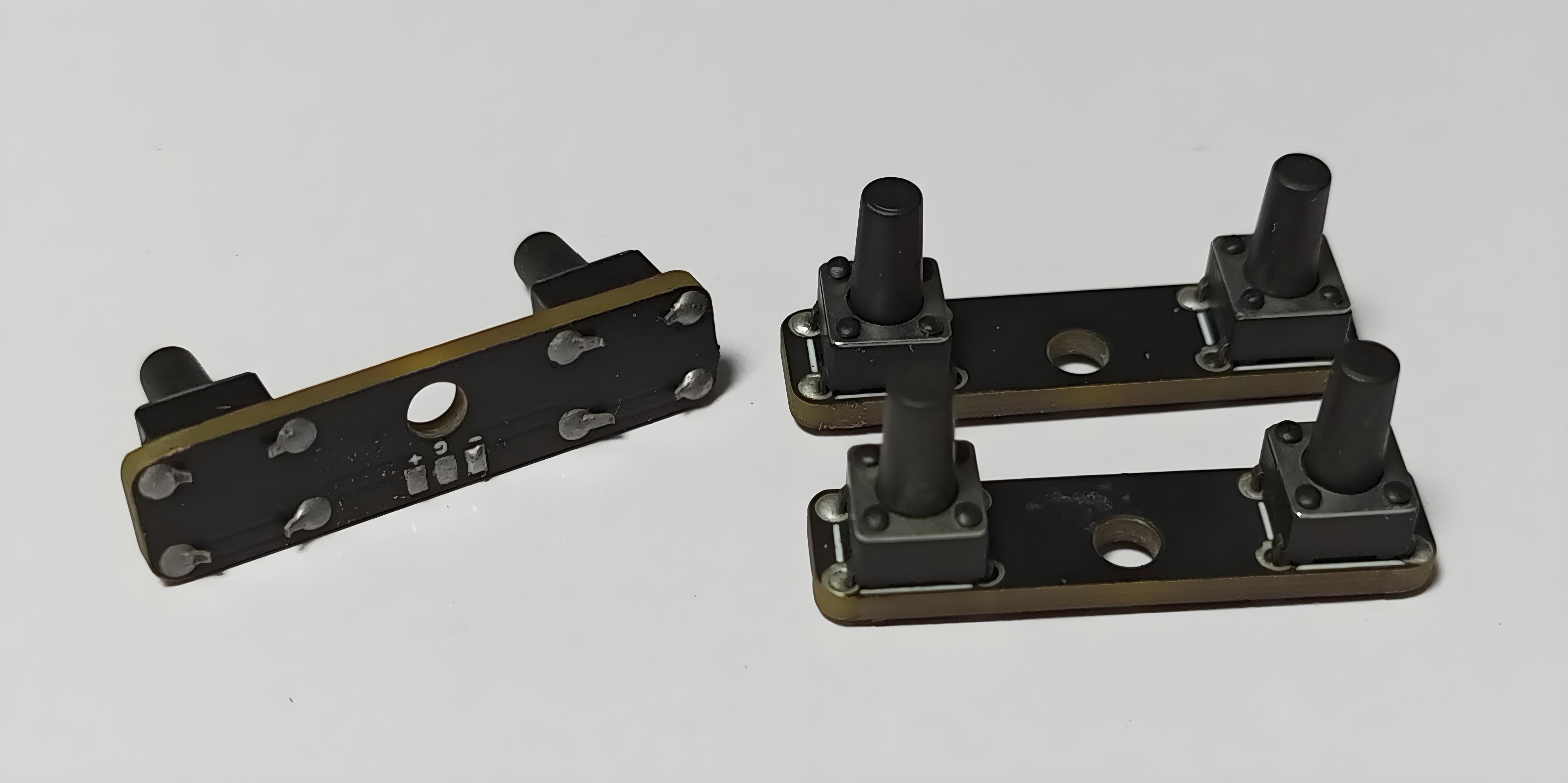
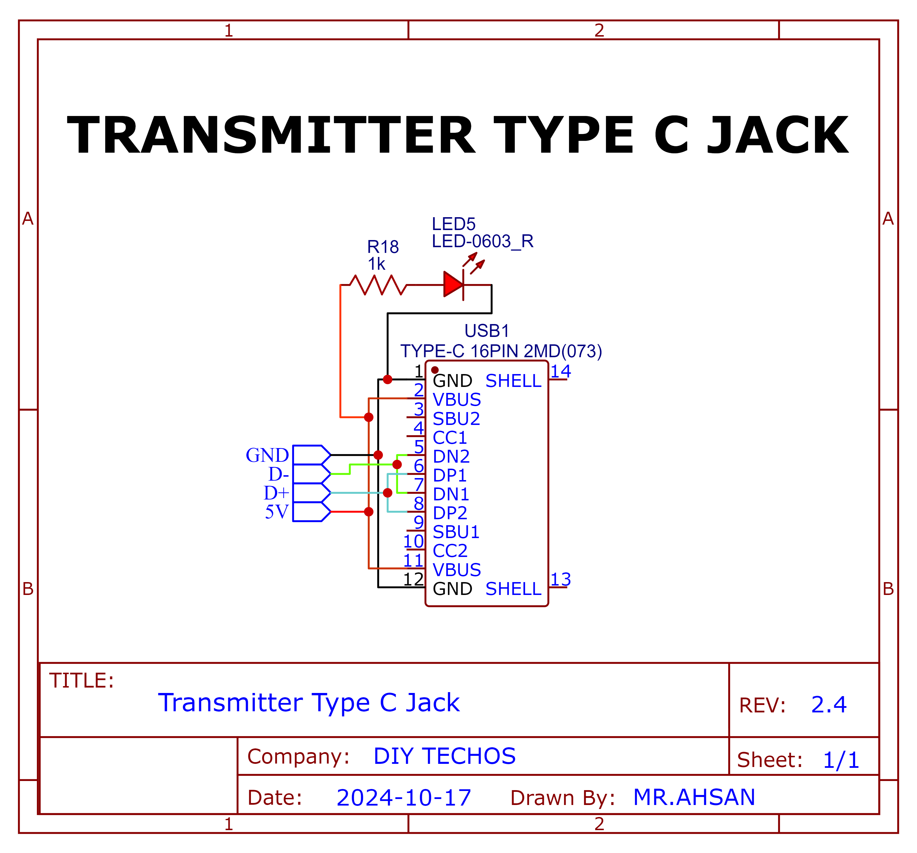
Type C Jack
Schematic and PCB Layout
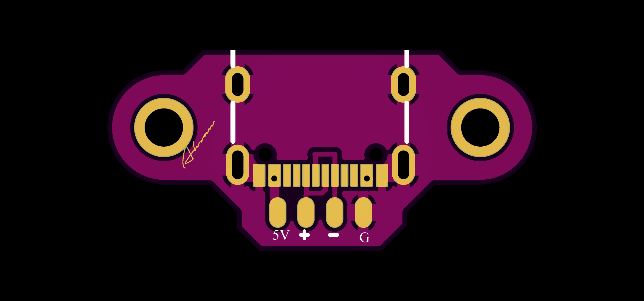
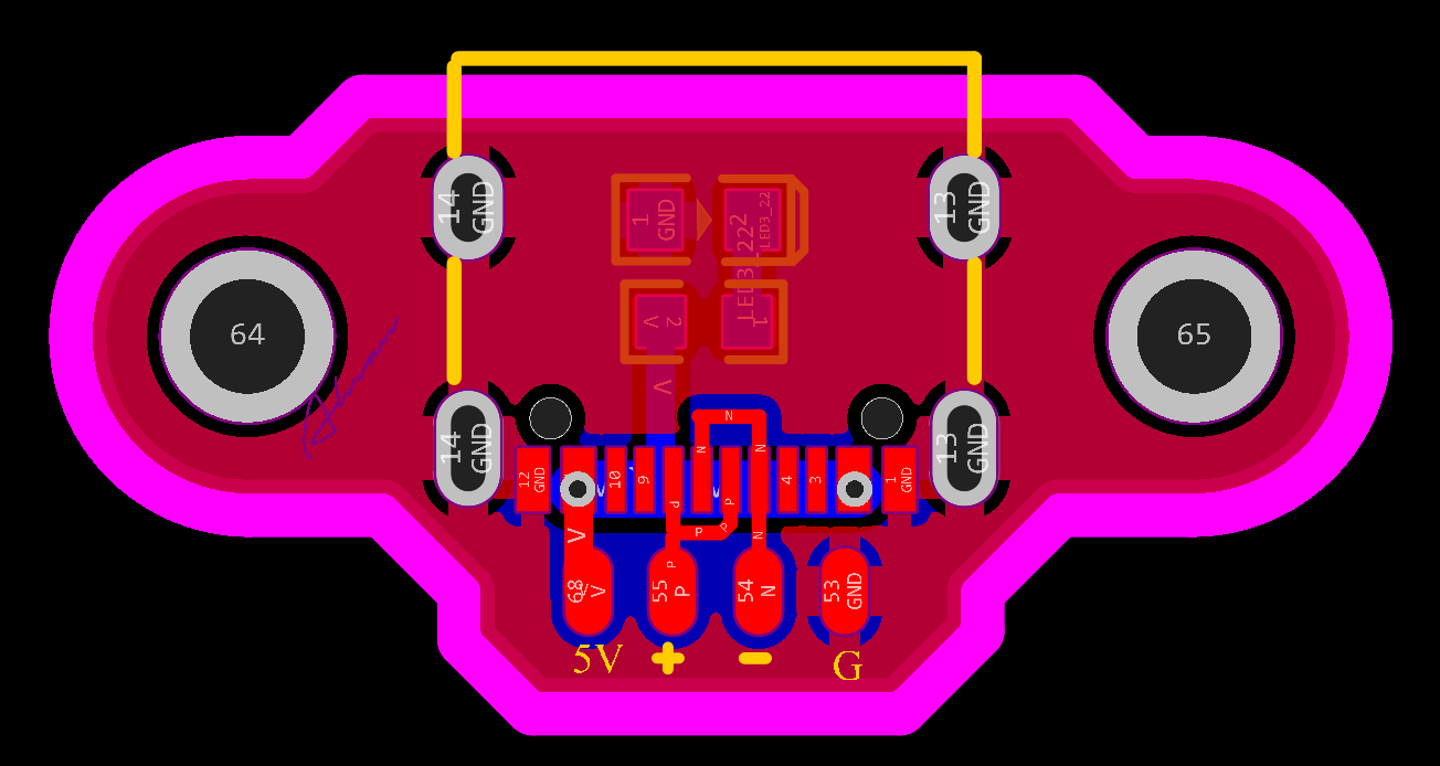 2D and 3D Preview


Final Result
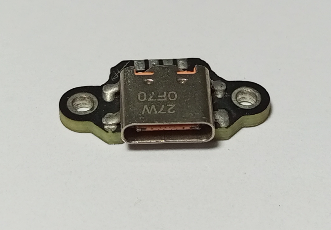
Receciver PCBs
8-channel PWM+PPM Receiver PCB
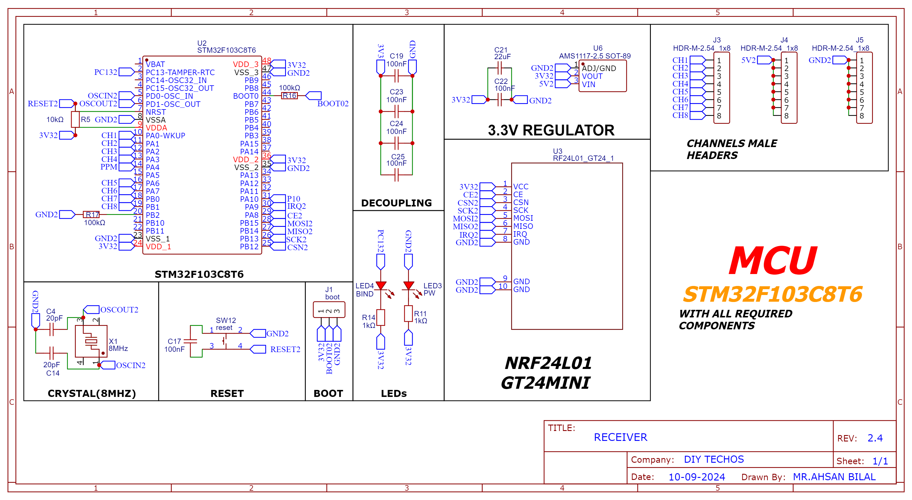
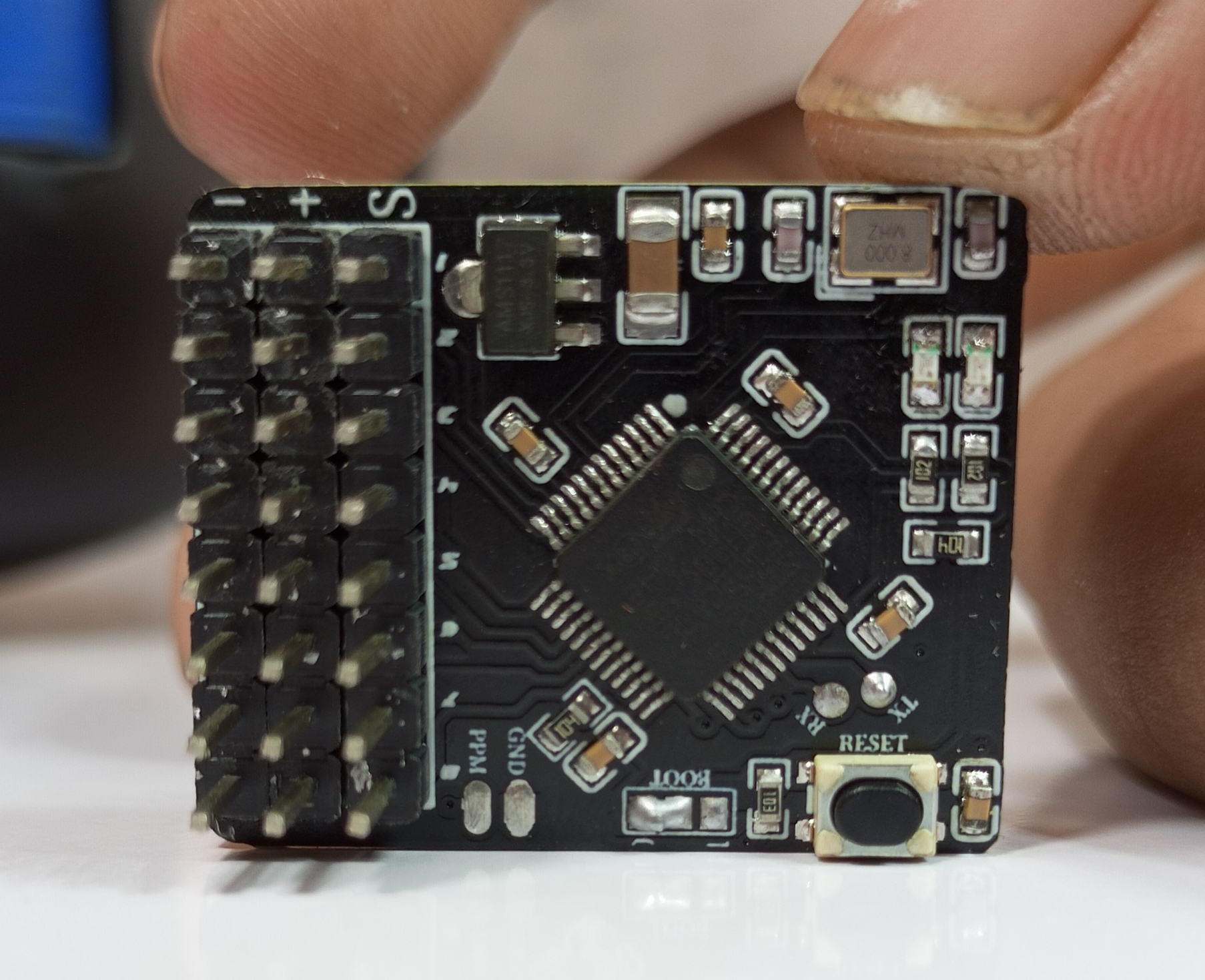
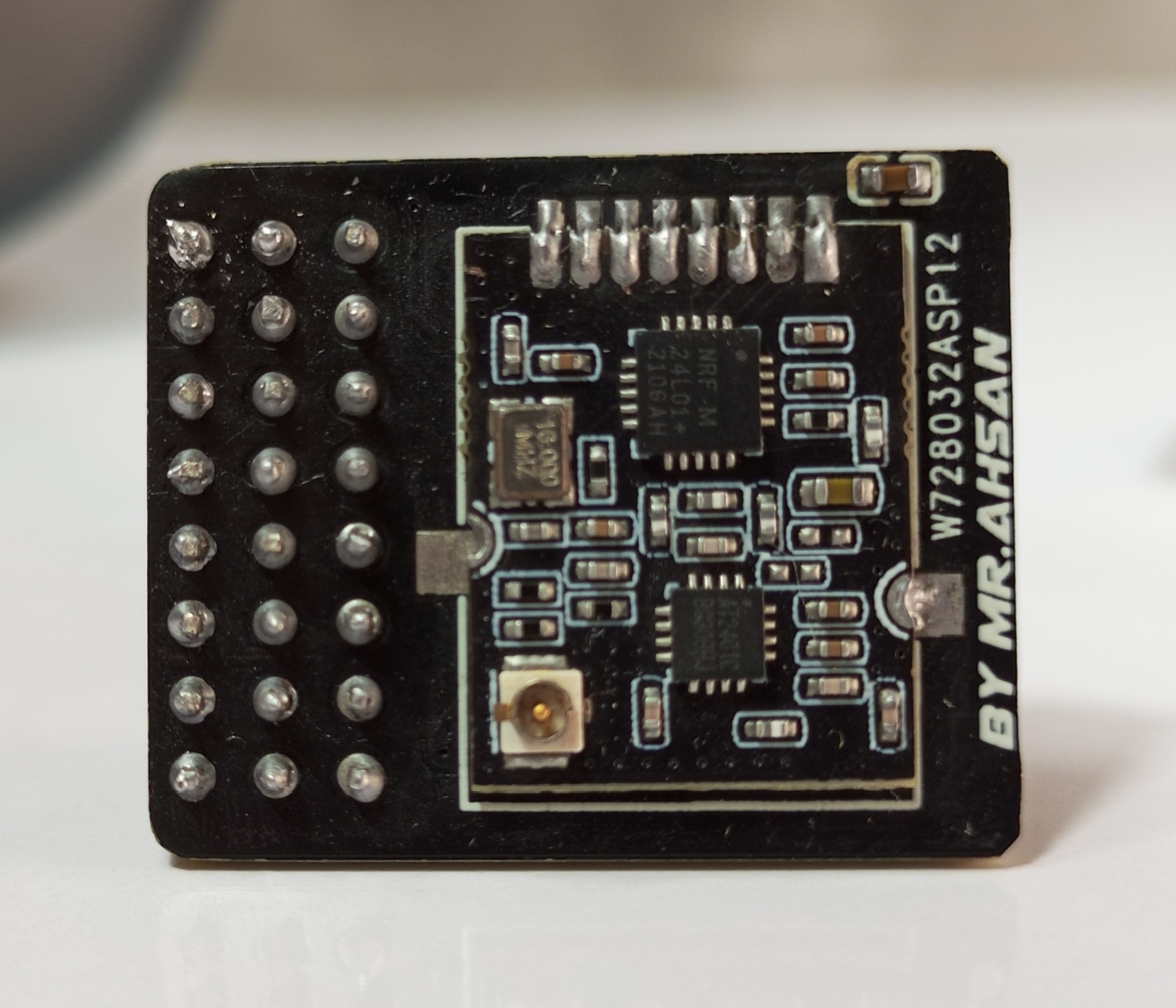
The 8-channel receiver supports both PWM and PPM outputs. It is based on the NRF24L01 and STM32F103C8T6 for signal decoding and generation.
Schematic and PCB Layout
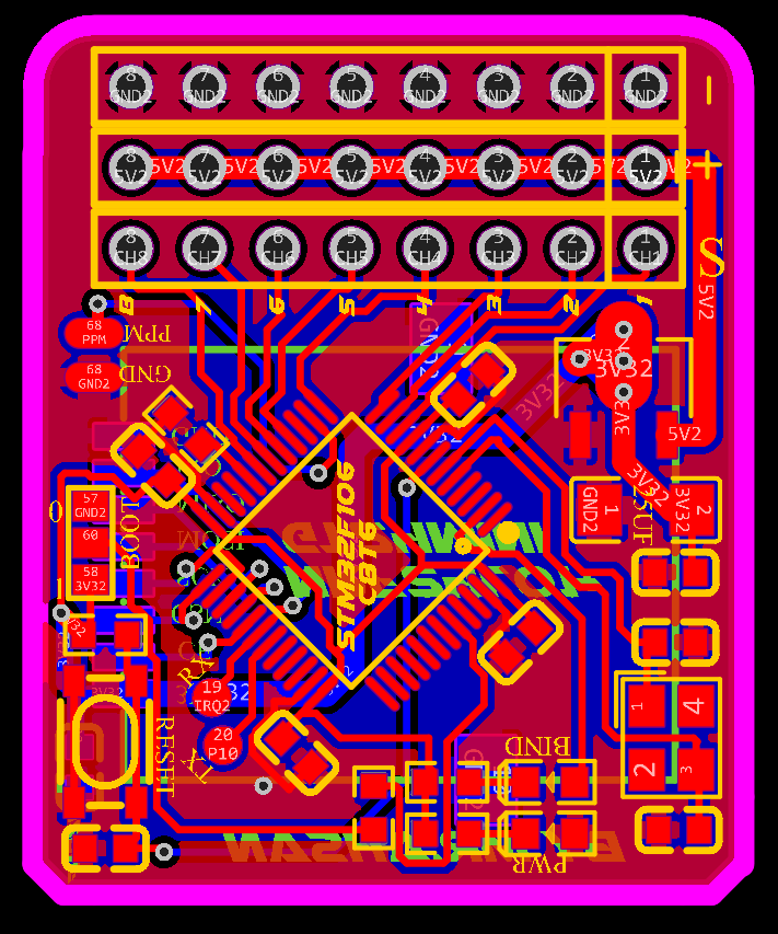
2D and 3D Preview

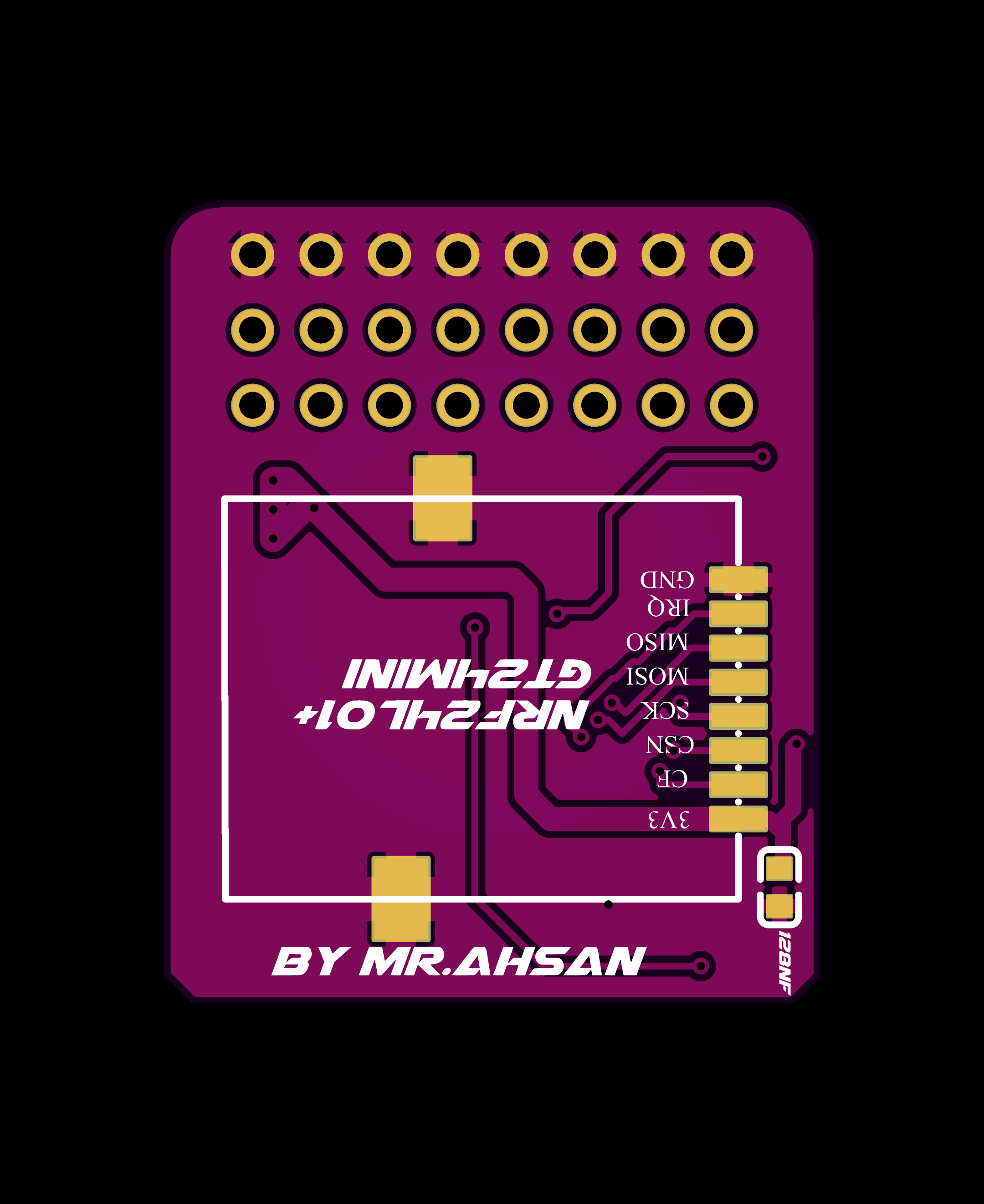


Final Result
PPM+SBUS Receiver PCB
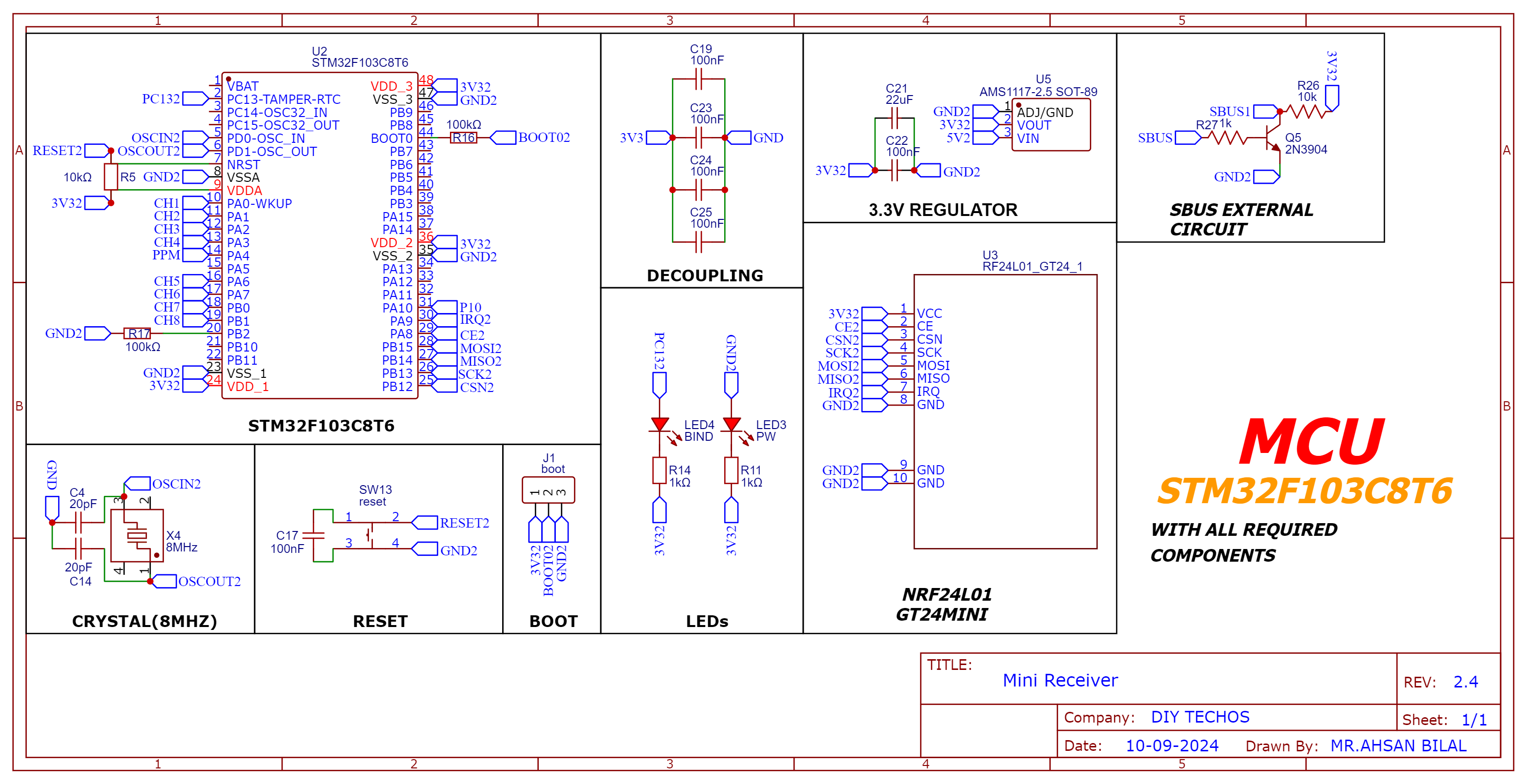
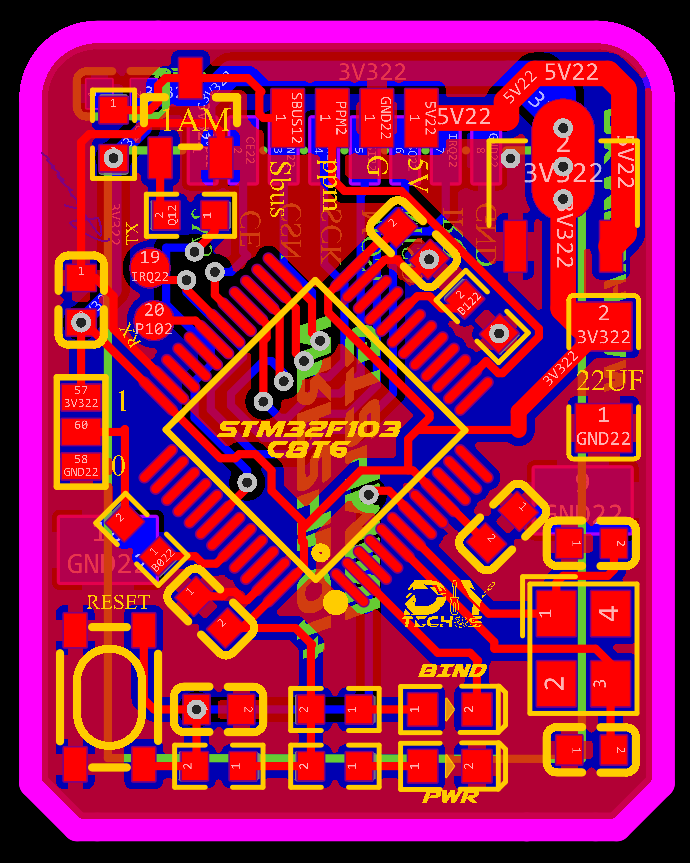
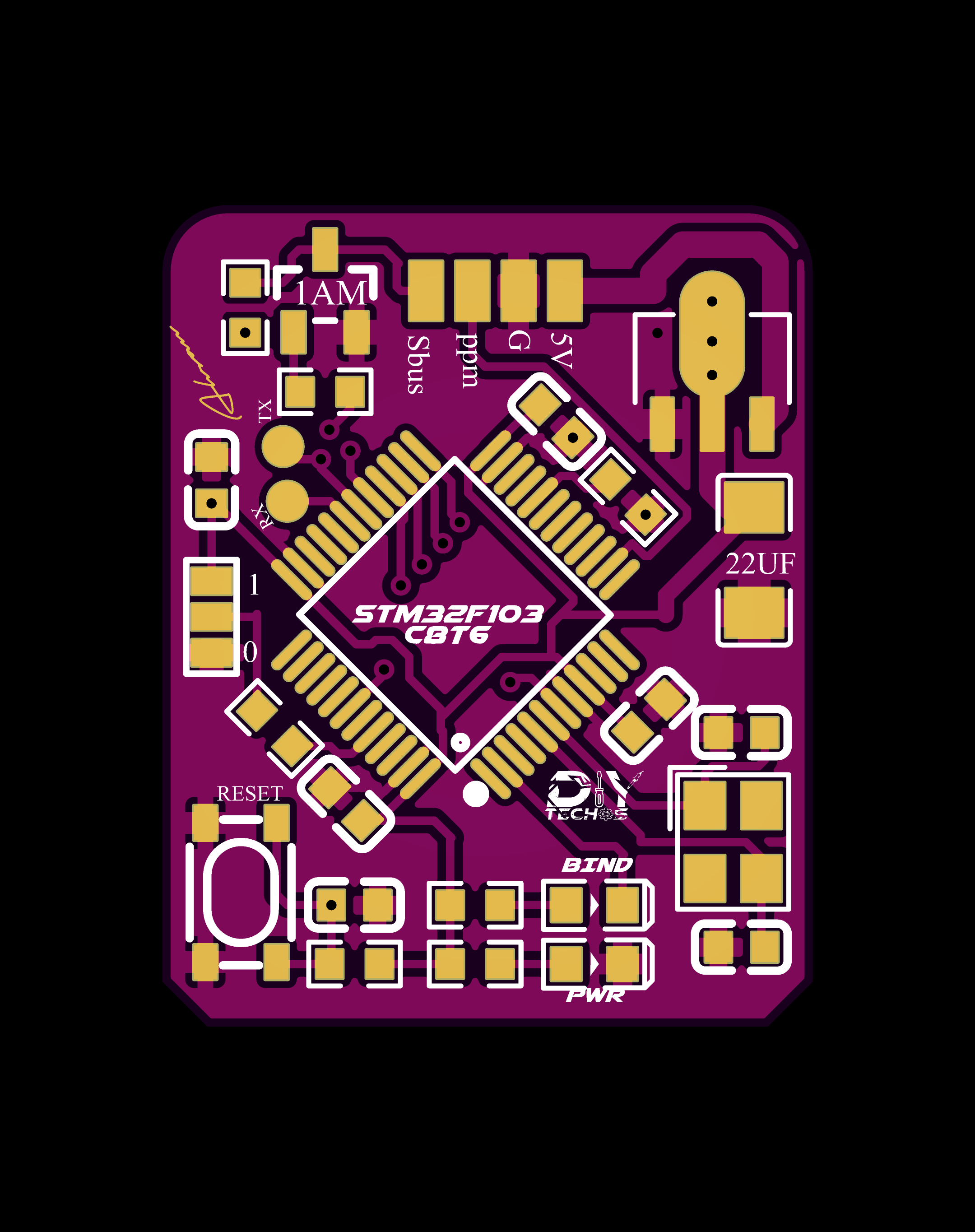
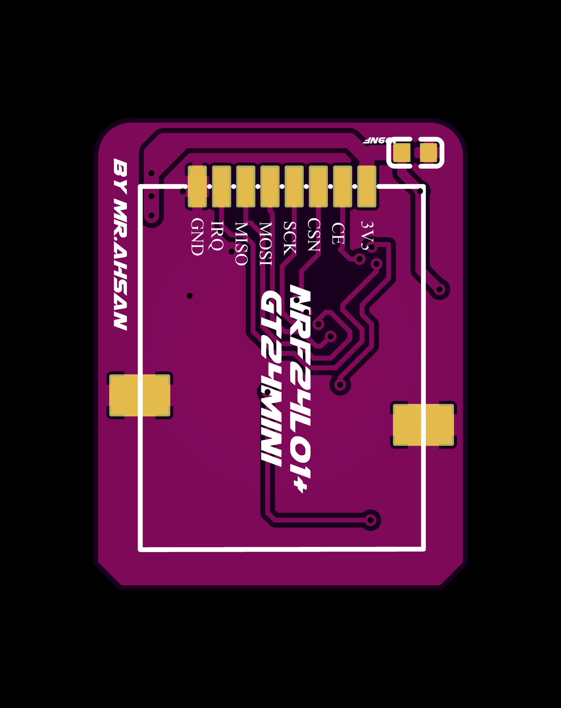
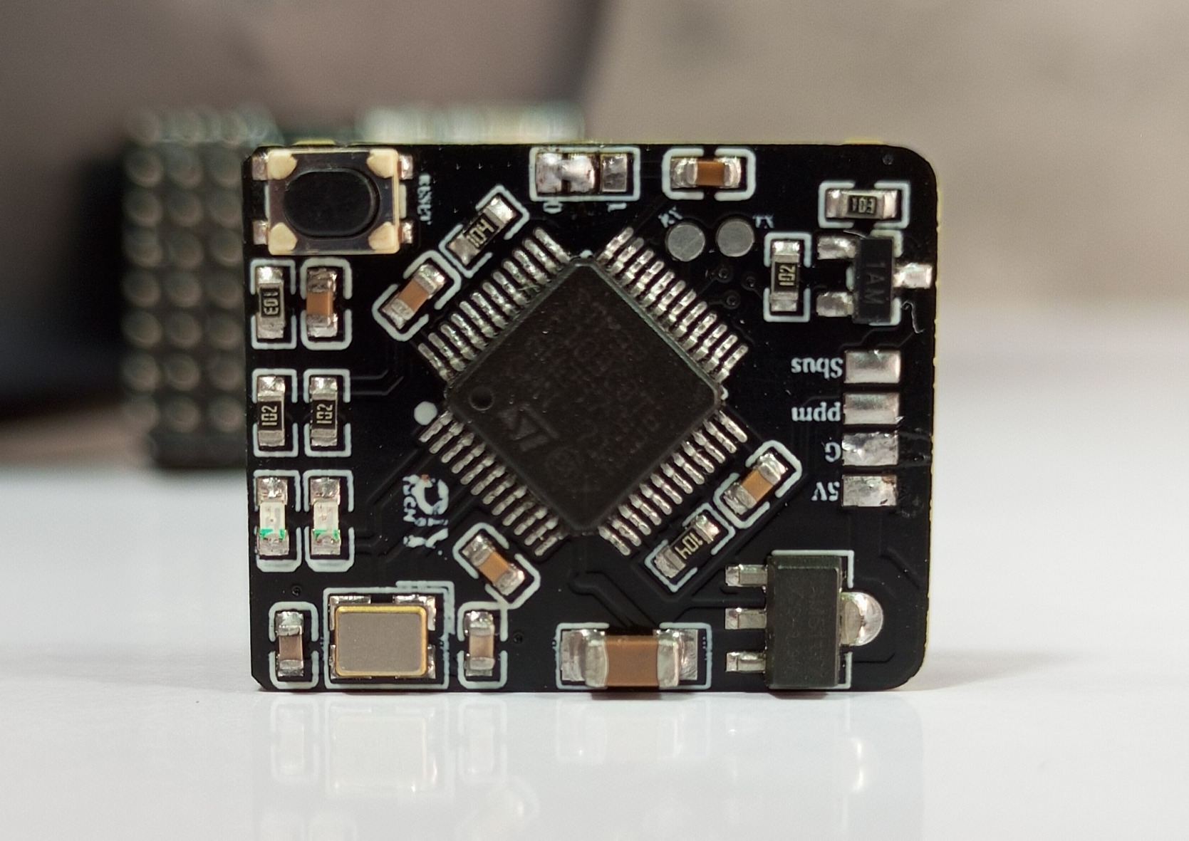
The PPM+SBUS receiver is another compact design focused on supporting more advanced control protocols. It also features the STM32F103C8T6 for signal processing and output.
Schematic and PCB Layout
2D and 3D Preview


Final Result
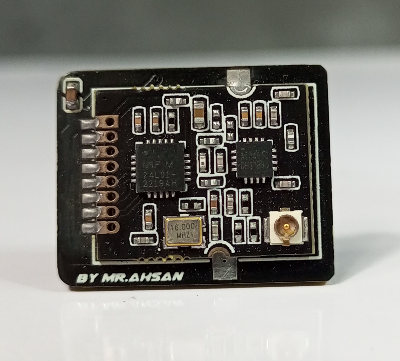
Visual and Physical Connections
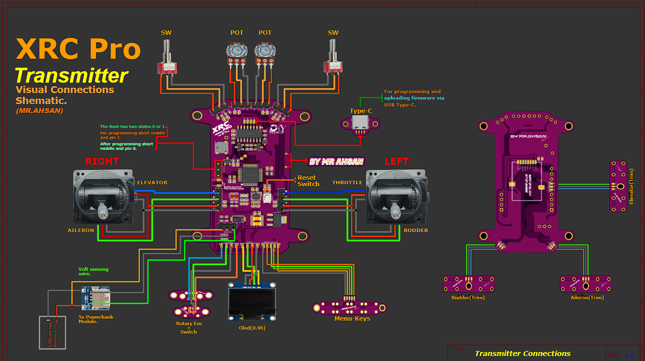
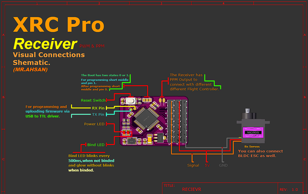
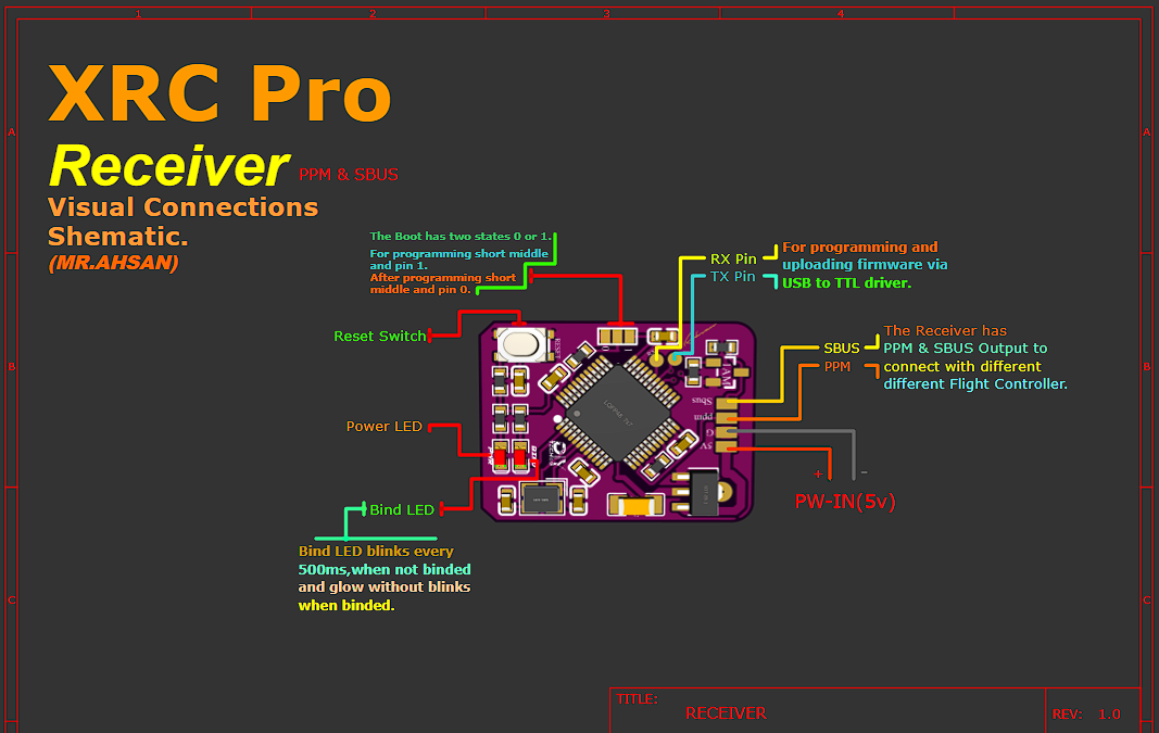
I’ve designed a detailed, color-coded connection schematic for all inputs and outputs, making it easy for anyone to assemble the XRC PRO transmitter and receivers. Additionally, I’ve included high-quality these images in PDF format, which you can download below.
Transmitter
Receiver(PWM+PPM)
Receiver(PPM+SBUS)
Firmware Overview
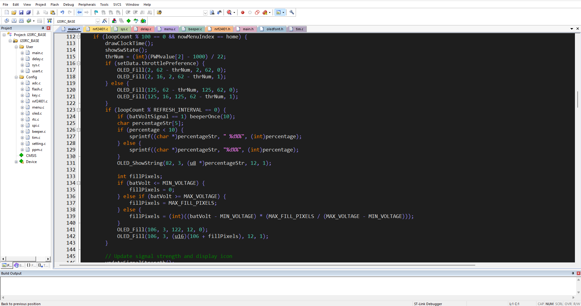
The XRC PRO's firmware is developed in Keil uVision using the CMSIS framework for STM32. It is fully open-source, with modular code to allow easy customization and extension of the system's capabilities. The main focus of the firmware is on handling communication between the transmitter and receivers, as well as managing the various control inputs.
Here the whole files in KeiluVision:
Below are the functions broken down from the main execution code, organized into smaller functional blocks. These functions are intended to be modular and handle specific tasks like initialization, signal strength calculation, display management, and event handling:
1. setup()
This function initializes all the necessary hardware peripherals and sets up the system for operation.
void setup() { // Initialize the delay function for timekeeping delayInit(); // Initialize USART for serial communication usart1Init(); // Initialize timers for PWM and other timing-related functions timer2Init(); timer3Init(); // Initialize DMA for memory transfers dmaInit(); // Initialize ADC for analog reading (e.g., battery level) adcInit(); // Initialize NRF24L01 for wireless communicationif (nrf24l01Init() == NRF_OK) { nrf24l01SetModeTX(); // Set NRF to transmit mode } else { // Handle NRF24L01 initialization error beepError(); } // OLED display initialization and show start-up screen oledInit(); oledShowLogo(); // Perform throttle self-check and configure NRF24L01 power mode throttleSelfCheck(); // Set up low-power mode if necessary lowPowerModeConfig(); }
2. loop()
The main loop that continuously runs during operation. It handles the display updates, signal strength checks, and key events.
void loop() { // Handle clock alarms and time display on the OLED handleClockAlarm(); // Update OLED display with throttle values and battery percentage displayThrottleValues(); displayBatteryLevel(); // Update signal strength display updateSignalStrength(); // Check for key events and menu navigation keyEventHandle(); // Handle menu events, if any menuEventHandle(); // Small delay to avoid constant polling delay(50); }
3. keyEventHandle()
Handles user input through key presses. This function updates throttle settings and processes navigation within the menu.
void keyEventHandle() { if (isKeyPressed(KEY_LEFT)) { // Adjust throttle channel for left-hand throttle adjustThrottleLeft(); } if (isKeyPressed(KEY_RIGHT)) { // Adjust throttle channel for right-hand throttle adjustThrottleRight(); } // Update OLED display with new throttle or menu setting oledRefresh(); // Save user data or preferences (e.g., throttle setting) saveUserDataToFlash(); }
4. addSignalStrengthSample()
Adds a new sample to the signal strength buffer and maintains a moving average of signal strength.
void addSignalStrengthSample(int newSignalStrength) { // Add new signal strength to the sample buffer signalStrengthBuffer[sampleIndex] = newSignalStrength; // Update sample index for circular buffer sampleIndex = (sampleIndex + 1) % SIGNAL_STRENGTH_BUFFER_SIZE; } 5. getAverageSignalStrength() Calculates the moving average of the signal strength based on the collected samples. int getAverageSignalStrength() { int sum = 0; for (int i = 0; i < SIGNAL_STRENGTH_BUFFER_SIZE; i++) { sum += signalStrengthBuffer[i]; } return sum / SIGNAL_STRENGTH_BUFFER_SIZE; }
6. displaySignalIcon()
Displays the signal strength icon on the OLED based on the signal strength percentage.
void displaySignalIcon(int signalStrengthPercent) { if (signalStrengthPercent >= 75) { oledDrawIcon(iconSignal100); } else if (signalStrengthPercent >= 50) { oledDrawIcon(iconSignal75); } else if (signalStrengthPercent >= 25) { oledDrawIcon(iconSignal50); } else if (signalStrengthPercent > 0) { oledDrawIcon(iconSignal25); } else { oledDrawIcon(iconSignalOff); } }
7.NRF24L01 Initialization
Initializes the NRF24L01 module and sets it in transmit mode.
void nrf24l01InitAndCheck() { // Initialize NRF24L01if (nrf24l01Init() == NRF_OK) { // Set NRF24L01 to transmit mode nrf24l01SetModeTX(); } else { // Handle NRF24L01 error by beeping and showing error message beepError(); oledShowErrorMessage("NRF24L01 ERROR"); } }
8.Sending Data Packets: sendDataPacket()
This function creates a 32-byte data packet and sends it using the NRF24L01 module. The packet contains a data header and channel values (PWM data).
u8 sendDataPacket(void) { u8 chPacket[32]; // Array to hold the data packet u16 t = 0; u8 sendIsOK; // Flag to check if sending is successful for (t = 0; t < 16; t++) { if (t == 0) // Add data header (0x00) { chPacket[2 * t] = 0x00; chPacket[2 * t + 1] = 0x00; } else if (t <= chNum) // Add PWM channel data { chPacket[2 * t] = (u8)(PWMvalue[t - 1] >> 8) & 0xFF; // High byte of 16-bit PWM value chPacket[2 * t + 1] = (u8)PWMvalue[t - 1] & 0xFF; // Low byte of 16-bit PWM value } else // Fill unused bytes with 0xFF (padding) { chPacket[2 * t] = 0xFF; chPacket[2 * t + 1] = 0xFF; } } sendIsOK = NRF24L01_TxPacket(chPacket); // Transmit the packetreturn sendIsOK; // Return status of the transmission (success or failure) }
9.Signal Strength Calculation: getSignalStrength()
This function measures the signal strength by sending multiple packets and calculating the percentage of successful transmissions.
int getSignalStrength(void) { const int totalPackets = 40; // Total number of packets to sendint successfulPackets = 0; // Counter for successful transmissions if (setData.NRF_Mode == ON) // If the NRF mode is ON { NRF24L01_TX_Mode(setData.NRF_Power); // Set NRF to transmit mode } else { NRF24L01_LowPower_Mode(); // Otherwise, set it to low-power mode } // Loop to send multiple packetsfor (int i = 0; i < totalPackets; i++) { if (sendDataPacket() == TX_OK) // If the packet was sent successfully { successfulPackets++; // Increment success counter } delay_us(700); // Short delay between transmissions } // Calculate signal strength as a percentage of successful packetsint signalStrength = (successfulPackets * 100) / totalPackets; return signalStrength; }
10. updateSignalStrength()
Updates the signal strength display and checks if the receiver is connected. It also adds a new sample to the signal strength buffer.
void updateSignalStrength() { // Get current signal strength from NRF24L01int currentSignalStrength = nrf24l01GetSignalStrength(); // Add the sample to the signal strength buffer addSignalStrengthSample(currentSignalStrength); // Calculate the average signal strengthint avgSignalStrength = getAverageSignalStrength(); // Display the corresponding signal strength icon displaySignalIcon(avgSignalStrength); // Check if receiver is connectedif (avgSignalStrength > SIGNAL_STRENGTH_THRESHOLD) { receiverConnected(); } else { receiverDisconnected(); } }
11. menuEventHandle()
Handles the user interface menu and responds to user input for changing settings.
void menuEventHandle() { // Check if a specific menu item is selectedif (isMenuItemSelected(MENU_ITEM_PWM_ADJUST)) { adjustPWMSettings(); } if (isMenuItemSelected(MENU_ITEM_CHANNEL_CALIBRATION)) { calibrateChannels(); } // Refresh OLED display with updated menu or settings oledMenuRefresh(); }
12. Battery Voltage Display
Updates the battery level icon and percentage on the OLED based on the battery voltage. void displayBatteryLevel() { float batteryVoltage = readBatteryVoltage(); int batteryPercent = convertVoltageToPercentage(batteryVoltage); // Display the battery icon and percentage on the OLED oledDrawBatteryIcon(batteryPercent); if (batteryVoltage < BATTERY_WARNING_THRESHOLD) { // Beep to warn low battery beepWarning(); } }
13. Clock and Alarm Handling
Handles the clock and alarm functionality, beeping when an alarm is triggered.
void handleClockAlarm() { // Check if the clock alarm is activeif (isAlarmActive()) { // Beep if the alarm time is reached beepAlarm(); // Display alarm icon on the OLED oledDrawIcon(iconAlarm); } // Update the time on the OLED display displayCurrentTime(); }
These functions represent the core operations of the system, which handles initialization, user input, signal strength monitoring, display updates, and more. Each function focuses on a specific aspect of the overall operation, making the code more modular and easier to manage.
Firmware Uploading
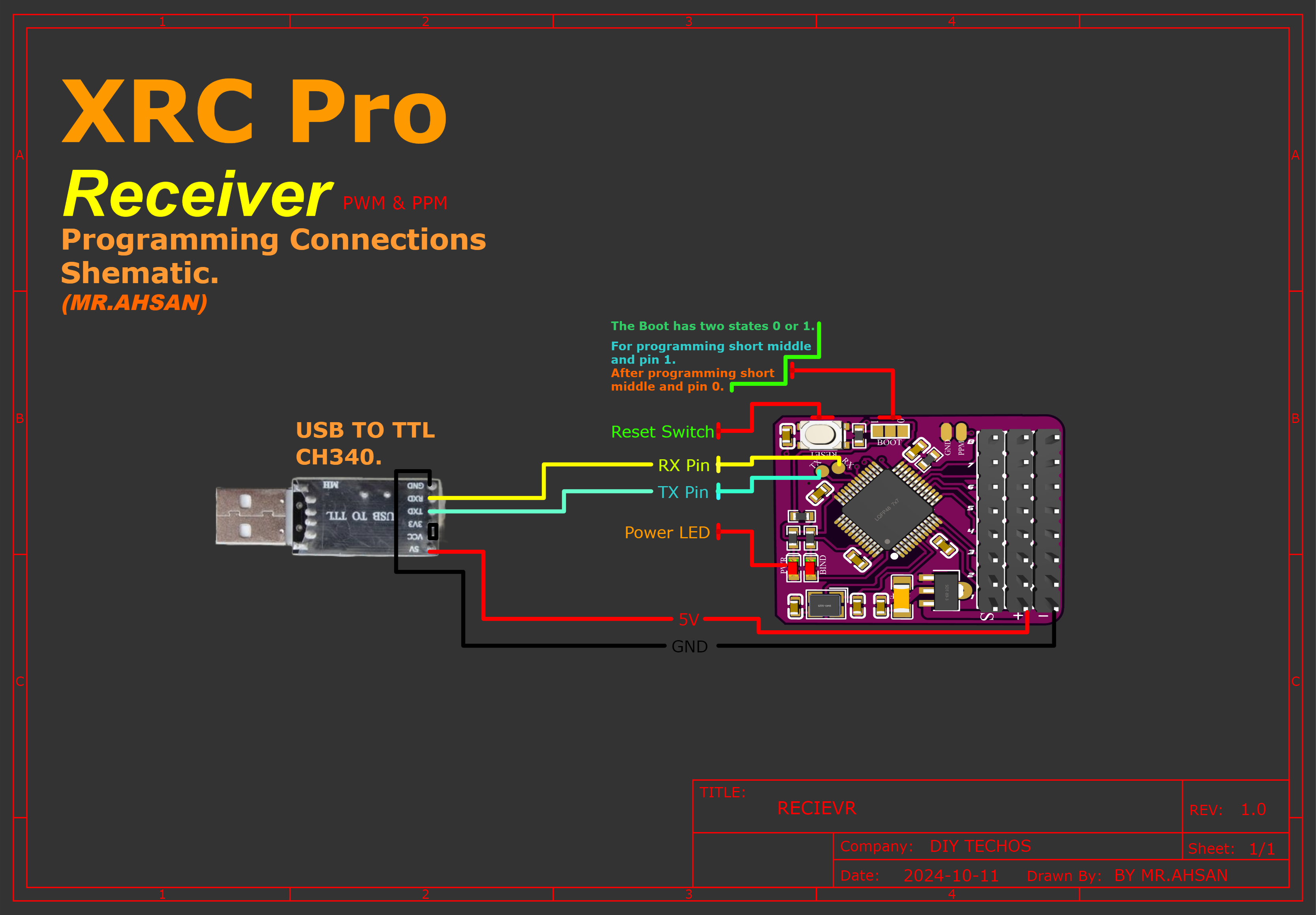
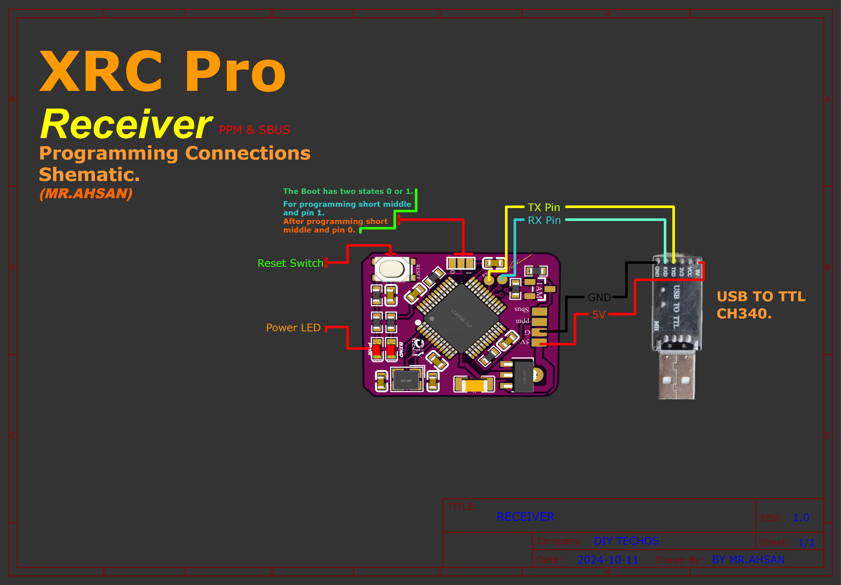
To upload the firmware to the transmitter and receivers, follow the connection diagram below. It shows how I connected the CH340 USB-to-TTL adapter to both the transmitter and receivers.
Connections
Transmitter
There are two methods of uploading code into transmitter.First,you can directly upload the code via USB TYPE-C Interface. Second,you can upload the code with the help of USB to TTL (ch340 driver).

Rceiver(PWM+PPM)
Receiver(PPM+SBUS)
Software
Download and install the STMicroelectronics Flash Loader Demonstrator software: Click to download
Steps
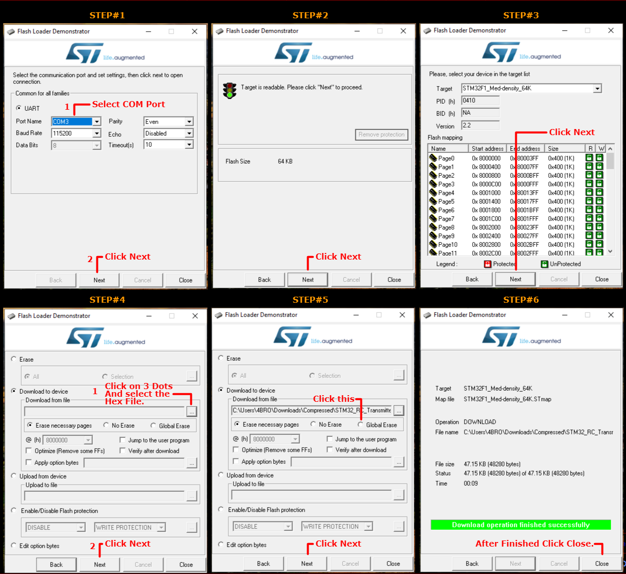
Follow:
- Plug the USB serial converter into the PC.
- Press the reset button on the STM32 board.
- Select the COM port in the software.
- Click 'Next,Next and Next.
- Select Download to device.Click on 3 dots and select the hex file.
- Select Global Erase.After that Click on Next
- Within 15 seconds, the code will be uploaded to the device.
- After finsihed.Click Close.
XRC PRO: Open-Source RC Transmitter and Receiver System
*PCBWay community is a sharing platform. We are not responsible for any design issues and parameter issues (board thickness, surface finish, etc.) you choose.

Raspberry Pi 5 7 Inch Touch Screen IPS 1024x600 HD LCD HDMI-compatible Display for RPI 4B 3B+ OPI 5 AIDA64 PC Secondary Screen(Without Speaker)
BUY NOW- Comments(6)
- Likes(7)
-
 Engineer
Nov 26,2025
-
 Engineer
Sep 04,2025
-
 Thomson Dalton
Apr 26,2025
-
 Engineer
Apr 03,2025
-
 Engineer
Dec 12,2024
-
 Engineer
Nov 10,2024
-
 DIY TECHOS MR AHSAN BILAL
Nov 08,2024
- 0 USER VOTES
- YOUR VOTE 0.00 0.00
- 1
- 2
- 3
- 4
- 5
- 6
- 7
- 8
- 9
- 10
- 1
- 2
- 3
- 4
- 5
- 6
- 7
- 8
- 9
- 10
- 1
- 2
- 3
- 4
- 5
- 6
- 7
- 8
- 9
- 10
- 1
- 2
- 3
- 4
- 5
- 6
- 7
- 8
- 9
- 10
 More by DIY TECHOS MR AHSAN BILAL
-
 XRC PRO: Open-Source RC Transmitter and Receiver System
OverviewThe XRC PRO is an advanced, open-source RC transmitter and receiver system designed to offer...
-
 LED strip PWM/RGB cascadable controller
OverviewThis project presents a versatile LED strip controller, which is based on the STC8G1K08A mic...
-
 STM32F722 flight control
Project Overview:This flight controller board is designed with innovation and user-friendliness in m...
-
 Portable Mini Weather Station: Real-Time Weather Updates with Web Configuration
OverviewThe Portable Mini Weather Station is a compact and versatile device designed to provide real...
-
 USB3.0 Gigabit LAN-RTL8153B
OverviewThis project is a high-performance Gigabit USB 3.0 network card designed around the RTL8153B...
-
 STM32F103C8T6 minimum system board
OverviewThis project is a minimalistic system board designed around the STM32F103C8T6 microcontrolle...
-
 WCH-LinkE-R0-1v3 Debugger
Overview The WCH-LinkE-R0-1v3 Debugger is a versatile and powerful tool designed for online debuggin...
-
 MAKE 8CH RC TRANSMITTER AND RECEIVER WITH STM32&NRF24L01
OverviewThe 8-channel RC transmitter and receiver system crafted for the PCBWay 6th Contest is a hig...
-
 MAKE 8CH RC TRANSMITTER AND RECEIVER WITH STM32&NRF24L01
OverviewThe 8-channel RC transmitter and receiver system crafted for the PCBWay 6th Contest is a hig...
-
 AMAZING DIY DIGITAL OSCILLOSCOPE
Working PrincipleThis mini oscilloscope project aims to create a compact and user-friendly device fo...
-
 AMAZING DIY DESKTOP CHARGING STATION
Four-way Desktop Smart Charging StationThis is a practical intelligent multi-channel desktop charger...
-
 AMAZING DIY DESKTOP CHARGING STATION
Four-way Desktop Smart Charging StationThis is a practical intelligent multi-channel desktop charger...
-
 Advanced 8-CH RC Transmitter and Receiver using stm32f103 and Nrf24l01
OverviewThe 8-channel RC transmitter and receiver system crafted for the PCBWay 6th Contest is a hig...
-
 Testing SBUS & PPM Signals on DIY STM32 RC Transmitter & Receiver! 🎮📡 | Advanced Control Verification | DIY TECH DEEPLY
IntroductionWelcome to DIY TECH DEEPLY! In this comprehensive guide, we'll delve into the intricacie...
-
 DIY RC Transmitter & Receiver with stm32 🎮🚁 | 8 channels pwm,ppm,sbus | DIY TECH DEEPLY
OverviewThe 8-channel RC transmitter and receiver system crafted for the PCBWay 6th Contest is a hig...
-
 UNLOCKING THE SECRET OF UNI-T 203+ TO MAKE RECHARGEABLE.
OverviewEmbark on a thrilling DIY journey as we delve into the Uni-T 203+ from Cell to Battery Conve...
-
 Advanced 8-Channel RC Transmitter and Receiver using stm32f103c8t6,nrf2l01.(Totally Diy)
OverviewThe 8-channel RC transmitter and receiver system crafted for the PCBWay 6th Contest is a hig...
-
 2-Axis Servo-Based CNC Pen Plotter (Fully Hand Crafted).
IntroductionHey there! I'm excited to share my cool project with you - it's a 2-axis servo-based CNC...
-
A Compact Charging Breakout Board For Waveshare ESP32-C3
477 3 4 -
AI-driven LoRa & LLM-enabled Kiosk & Food Delivery System
487 2 0 -
-
-
-
ESP32-C3 BLE Keyboard - Battery Powered with USB-C Charging
683 0 1 -
-
mammoth-3D SLM Voron Toolhead – Manual Drill & Tap Edition
671 0 1 -
-
AEL-2011 Power Supply Module
1342 0 2 -
AEL-2011 50W Power Amplifier
1224 0 2


