


Leningrad_gerber
When Sinclair released the original ZX Spectrum in 1982, it was designed with a chip called the ULA, short for 'uncommitted logic array'. This chip combined a large amount of logic functions into a single custom-made package, significantly lowering the component count and cost.
In modern times, when it costs about as much to buy an old Spectrum as it does to build your own, building a Spectrum based on the original circuit is severely hindered by the fact that these chips were only made for the Spectrum and different versions were used on each PCB revision, making them extremely rare today.
The ULA also generates a lot of heat, so due to being installed without a heatsink and placed into a case with no ventilation (as was done in the original Spectrum), overheating is a common failure point. As a result, most new old stock ULAs have already been used to repair existing machines.
Therefore, it has become something of an art form in electronics to design a Spectrum clone that only uses parts that are still readily available. The most well known example of this is probably the Superfo Harlequin 128, a 100% compatible Spectrum 128K clone built entirely with off-the-shelf parts. The only downside of this design is its high chip count. (61 ICs)
The art of cloning the ZX Spectrum is not a modern concept, however - in fact, it's almost as old as the Spectrum itself! Countries where original Sinclair hardware was difficult to obtain (due to economic tariffs, sanctions, etc.) often had very lenient copyright laws, allowing the existence of domestic industries dedicated to replicating the Spectrum's hardware with the parts available to them. This resulted in computers with a large software base immediately upon release, since only one copy of a program needed to be smuggled into the country for it to be copied and distributed en masse.
The most notable example of this is probably the Soviet Union and surrounding Eastern Bloc. Development of clones in this part of the world began around 1985, with early models consisting of around 50-60 ICs. However, the complexity of these early homemade clones made them expensive and difficult to build and troubleshoot, so they weren't very popular.
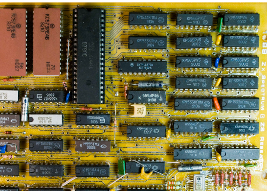
In 1988, an electronics engineer from the city of Leningrad named Sergey Zonov developed a Spectrum clone using only 41 ICs, resulting in a clone that was decently affordable, even on the humble average salary of the USSR. This was an immediate success, and computers based on the "Leningrad variant" (later renamed Leningrad-1 to differentiate from the subsequent Leningrad-2) were mass produced for almost a decade, becoming the most popular ZX Spectrum variant in the former USSR.
The USSR used its own naming scheme for ICs, but all the Soviet ICs this computer was designed for have exact Western equivalents. As far as I know, this is still the simplest ZX Spectrum clone to date that doesn't use a programmable logic array in place of off-the-shelf logic.
Technical Description
The relative simplicity of the Leningrad-1's design comes at the cost of 100% compatibility. The majority of software works just fine, but certain programming tricks that rely on specific hardware timing may not look or sound like they're supposed to.
Having tested my Leningrad-1 with a decent amount of programs, I'd say 90-95% work with no problems whatsoever, while 97-98% are usable/playable (e.g., no game-breaking glitches).
The composite video output is monochrome, with color video available from a SCART connector (currently not working as of Revision 0) and a DIN-8 connector intended for connection to a custom external video adapter (e.g., VGA).
The commands that are used to play Yamaha AY audio on more advanced Spectrum models appear to conflict with the border drawing circuitry. This results in the border flickering when programs attempt to play AY music.
I have made an effort to make this computer as easy to build as possible. The value of almost every component (excluding pin headers and two connectors) is printed on the silkscreen, so it's possible to assemble the whole thing without having to check the bill of materials.
To aid in ease of construction (and cost reduction), the top and bottom of the static-sensitive system PCB can be protected without having to fabricate a case. The keyboard PCB is designed to mount on top of the system PCB with standard nylon M3 screws and standoffs. Since most PCB fabricators require that you order a minimum of 5 boards per design, you can use one of the spare keyboard PCBs to cover the bottom side of the system PCB.
The keyboard and system PCBs are mounted together with 6 standoffs. The keyboard has an extra 4 holes for standoffs that go through the keyboard and sit on top of the system PCB. These are intended to add structural stability - perfect for fast-paced action games!
Leningrad_gerber
Project images are for reference only. Actual production is based on the manufacturing files on the project page.
Please review the designer's notes (e.g., PCB thickness) and select the appropriate options.
PCBWay is not responsible
for issues caused by unsuitable parameter selections.
For more important ordering information, please refer to
Read More


Raspberry Pi 5 7 Inch Touch Screen IPS 1024x600 HD LCD HDMI-compatible Display for RPI 4B 3B+ OPI 5 AIDA64 PC Secondary Screen(Without Speaker)
BUY NOW

- Comments(1)
- Likes(3)
More by Garri Lopurko
-
Programmable Mist Maker - XIAO / QT PY Extension
1061 2 1 -
RadioHAT - Raspberry Pi radio development platform
867 0 2 -
-
-
-
-
ARPS-2 – Arduino-Compatible Robot Project Shield for Arduino UNO
3323 0 6 -
A Compact Charging Breakout Board For Waveshare ESP32-C3
3933 3 8 -
AI-driven LoRa & LLM-enabled Kiosk & Food Delivery System
4320 2 2


