


 Top
Top
Chasers light up to 65 leds (0 to 64)
### DESCRIPTION
Chasers light up to 65 leds (0 to 64)
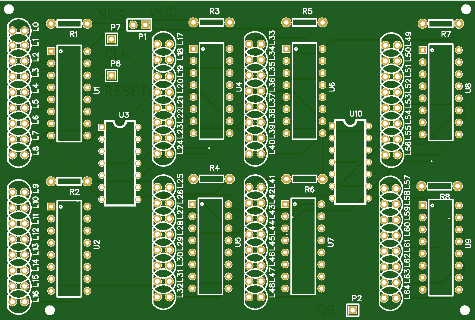
### TECHNICAL DETAILS / COMPONENTS
The symbols for the LEDs simply indicate the connection direction, the flat side for the cathode.
U1,2,4,5,6,7,8 and 9 are 4017 (decimal counter)
U3 and U10 are 7408 (quad 2-input AND gate)
R1,2,3,4,5,6,7,8 resistances whose value depends on the LEDs used
P1 is used to supply 5 volts (the square VCC for the positive)
P2 is the Q9 output of the last 4017 it must be connected to P8 (RESET)
P7 receives the clock signal (CLK), this signal is generated not another circuit (not on this PCB).
### LEARN / TOPIC / BUILD INSTRUCTIONS
You can limit the number of LEDs in the cycle, just connect the anode connection of the LED following the last LED lit with P8 (RESET).
Example: to light the LEDs L0 to L59 sequentially, then start the cycle again, connect the connection for the anode (rounded side of the symbol) from L60 to P8.
If you use all the same leds you can connect all the cathodes together and use only one R1 resistor
I use 3 of them to create a clock (see video)
Chasers light up to 65 leds (0 to 64)
*PCBWay community is a sharing platform. We are not responsible for any design issues and parameter issues (board thickness, surface finish, etc.) you choose.


Raspberry Pi 5 7 Inch Touch Screen IPS 1024x600 HD LCD HDMI-compatible Display for RPI 4B 3B+ OPI 5 AIDA64 PC Secondary Screen(Without Speaker)
BUY NOW


- Comments(0)
- Likes(4)
More by Baras Patrick
-
Programmable Mist Maker - XIAO / QT PY Extension
561 1 0 -
RadioHAT - Raspberry Pi radio development platform
440 0 1 -
-
-
-
-
ARPS-2 – Arduino-Compatible Robot Project Shield for Arduino UNO
2951 0 6 -
A Compact Charging Breakout Board For Waveshare ESP32-C3
3466 3 8 -
AI-driven LoRa & LLM-enabled Kiosk & Food Delivery System
3810 2 2


