|
KiCADKicad
|
The RP2040 Mini Board
Introduction
The electronic world is evolving to a complex and fascinating level. Manufacturers in these areas are coming up with more suitable and flexible components that are triggering advanced improvements in this area. The area of microcontrollers has not been left behind with more chips being pumped into the market. The RP2040 chip that has triggered more learning lessons in the area of automated home systems is already in the market. It is a product built by Raspberry Pi and it is in the long run fueling the microcontroller revolution triggering the rise of new platforms such as Arduino Nano RP2040 Connect, Raspberry Pi Pico, Wio RP2040 and so many others. Am going to document all you need to know about RP2040 where I will introduce it and list some projects, accessories, and products that can be built using the same microcontroller.

RP2040 chip
In February 2021, there was the introduction of the RP2040 into the market. The chip is built on dual-core Arm cortex-M0+ processors that are clocked at about 133MHz with an internal SRAM and an internal flash memory of 2MB and it can be coded in both C and C++ programming. It can also be programmed using the beginner’s MicroPython language. The chip has powerful hardware that can run machine learning frameworks such as the TensorFlow Lite.

Features of the RP2040
RP2040 caries around a noticeable signature of unique features such as ease of use, high performance, and relatively low cost. Besides very impressive technical values such as on-chip memory, rich peripherals, and a dual-core processor, the RP2040 chip can be coded with professionally preferred C++ and the beginner’s MicroPython programming languages.

With the chip, you are guaranteed high performance that is accompanied by low power consumption and extremely low leakage. You will note that it also has low power modes that help in extending its battery life. The feature makes the RP2040 suitable for applications that require a robust and longer use such as hobbyists and industrial use.
Another feature of the RP2040 is the programmable I/O subsystems which will provide more computing power to the users.
Below is the list of all the specifications of RP2040;
· Dual ARM Cortex-M0+ @ 133MHz
· Support up to 16MB off-chip Flash memory through a dedicated QSPI bus
· 264kByte on-chip SRAM located in independent banks
· Peripherals: 2SPI, 2 UARTs, 2 I2C Controllers, USB 1.1 Controller, 8 PIO State Machines, 16PWM
· DMA controller & Fully-connected AHB crossbar
· On-chip programmable LDO for generating a core voltage
· 2 on-chip PLLs for generating USB and core clocks
· Interpolator and integer divider peripherals
· 30 GPIO pins, where 4 are used for analog inputs
Using RP2040 to design Mini Board
The next step is how to design the RP2040 MINI board and this design I did it perfectly on KiCAD EDA. The requirements for the projects are listed in the image below;

Drawing the Schematic In KiCAD
Open KiCAD and lay down all the components listed above and do the interconnection as shown below. Check of the electrical rules compliant is done. The addition of footprints is done at this level too then the schematic is annotated to give the components a unique identity for example if you have two capacitors one is labeled as C1 and the other C2. After annotation, the netlists are generated and the schematic pushed to the PCB layout stage.

PCB Layout
After drawing the schematic, the next step is the PCB layout where the routing and even design of the 3D board are done. Here the size of the tracks on the board is calculated and determined. The 3D symbols and the footprints are confirmed to be in order. The edge cut is built up to define the size of the board. The board thickness is also confirmed at this level.

3D Output
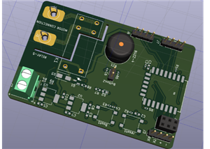
After a successful layout process, the generation of the 3D view is done, and below is the outcome of the process.

The design is complete and what you need to do is to generate the fabrication files such as the Gerber files and upload them to your favorite manufacturer for the final manufacturing. You can generate the files from KICAD by hitting FILE then FABRICATION OUTPUT and generate all the files under this category from BOM, to DRILL files and others. Also, hit on FILE and then PLOT to generate the Gerber file which is also crucial in the design process.
How is Fabrication ordered?
Search PCBway then click on the Instant Quote page to get to the window shown below.

At this point, you need to start feeding in the necessary information so that you can have your design ready for an approximate quote.
Select the board type input the size of your board, select the quantity that you need, and the type of the material for the final board eg F4R, and finally the thickness a shown below.

Hit calculate to be fed with your approximate price for the board as shown below;

Hit submit to cart then you will end up with the pop-up window where you need to submit your Gerber files. Just submit the GERBER files then wait for the engineers to give you the final quote for the job and after you make the payment, you will get the finished product within seven days.


The RP2040 Mini Board
*PCBWay community is a sharing platform. We are not responsible for any design issues and parameter issues (board thickness, surface finish, etc.) you choose.

Raspberry Pi 5 7 Inch Touch Screen IPS 1024x600 HD LCD HDMI-compatible Display for RPI 4B 3B+ OPI 5 AIDA64 PC Secondary Screen(Without Speaker)
BUY NOW- Comments(2)
- Likes(3)
-
 Engineer
Dec 23,2023
-
 Simon Mugo
Sep 21,2022
-
 Engineer
Sep 20,2022
- 0 USER VOTES
- YOUR VOTE 0.00 0.00
- 1
- 2
- 3
- 4
- 5
- 6
- 7
- 8
- 9
- 10
- 1
- 2
- 3
- 4
- 5
- 6
- 7
- 8
- 9
- 10
- 1
- 2
- 3
- 4
- 5
- 6
- 7
- 8
- 9
- 10
- 1
- 2
- 3
- 4
- 5
- 6
- 7
- 8
- 9
- 10
 More by Simon Mugo
-
 High Power Three Channel LED Driver
IntroductionI have been thinking about how to drive RGB LED patterns most simply. In my day-to-day r...
-
 433 MHz Radio Frequency Transmitter Module
IntroductionTwo devices can communicate with each other using radio frequencies and using an RF tran...
-
 Customized Servo Motor Driver Board
IntroductionServo motors, also called rotary or linear actuators, are designed for minimal control o...
-
 Arduino Customized L298M Dual Motor Driver Module
IntroductionThe Arduino Customized L298M Dual Motor Driver Module is designed to handle high-power D...
-
 Overvoltage Protection Board
PrecautionBefore making use of the circuit in this design project, ensure that you first set the var...
-
 Automatic Residential Lighting System Board Based on AT89C51
In our day-to-day activities, we often don't remember to switch off or on the lights in our rooms. T...
-
 The Energy Saving Bulb Board
The traditional incandescent bulb is an energy waster and it should be removed off shelves. My new t...
-
 ESP8266 MINI TEST BOARD
Design Of The SchematicThe schematic design is done in KiCAD. The process starts with finding the da...
-
 POWER SUPPLY FOR THE ESP8266
ESP8266 is a microchip of low cost that is produced by a company by the name of ESPPRESSIF stems. It...
-
 1N4148 INCOPORATING 741 IC TEMEPERATURE SENSOR
Creating a simple temperature sensor using a diode (1N4148) and an operational amplifier (741 IC) is...
-
 TSL25911 Light Sensor
IntroductionWe interact with different intensities and strengths of light in our daily activities. T...
-
 SIM800 GPS module
ElevatorThis project demonstrates how you can develop various GPS/ GPRS and SMS capability developme...
-
 nRF51822 Mini Evaluation Board
IntroductionDemand for development and evaluation boards the world over has increased. Due to such d...
-
 Customized LM393D Soil Moisture Sensor Board
ElevatorThe project is good at converting analog signals from the soil to digital signals for soil m...
-
 PAM8403 Amplifier Module
IntroductionThis is a simple project for improving your musical or audio entertainment by powering y...
-
 741 IC Bass Booster
IntroductionIn this project, we are going to design a bass booster circuit using the 741 IC. This is...
-
 LM317 AND LM337 ADJUSTABLE POWER SUPPLY CIRCUIT BOARD
IntroductionThe LM317/LM337 symmetrical power supply circuit is an electronic setup for meeting the ...
-
 230V AC to 1.5V DC PCB for Your Application
IntroductionA power management integrated circuit (PMIC) is utilized to supply the necessary power t...
-
ARPS-2 – Arduino-Compatible Robot Project Shield for Arduino UNO
540 0 0 -
A Compact Charging Breakout Board For Waveshare ESP32-C3
994 3 6 -
AI-driven LoRa & LLM-enabled Kiosk & Food Delivery System
875 2 0 -
-
-
-
ESP32-C3 BLE Keyboard - Battery Powered with USB-C Charging
1148 0 1 -
-
mammoth-3D SLM Voron Toolhead – Manual Drill & Tap Edition
978 0 1 -
-
AEL-2011 Power Supply Module
1741 0 2


