PCBWay Community
Search title or content
Search
PCBWay
PCB Instant Quote
CNC | 3D Printing
Login
Sign Up
More Notifications
No notifications.
My Profile
My projects
My Likes
My Deals
My Goods for Bazaar
Settings
Sign Out
Projects
Categories
DIY Electronics
Arduino
Hardware
Audio
Computers & USB
Breakout Board Projects
Home Automation
LED Displays & Matrices
IoT
Robotics
View all categories
By Source Files
Onju Voice - AI assistant replacement to Google Nest Mini by @justLV
DIY 1kW Open Source MPPT Solar Charge Controller
LogicAnalyzer V6.0
kv4p HT v1.7b
Tad Boy Color
QuinLED-Dig-Uno
Bike Fingerprint - PCB
SummerCart64 - a fully open source N64 flashcart
Solar Powered WiFi Weather Station V2.0
Arduino RC engine sound & light controller with inertia simulation for ESP32
Frog Boy Color
iSpndel_4.0
View all source files projects
Featured Projects
Onju Voice - AI assistant replacement to Google Nest Mini by @justLV
DIY 1kW Open Source MPPT Solar Charge Controller
LogicAnalyzer V6.0
Featured
Source Files
Video
View all projects
Questions
Sponsorships
Feedback
Videos
Blog
Store
PCB Design
Contest
- 8th Project Design Contest
- 7th Project Design Contest
- KiCad Design Contest
- 6th Project Design Contest
- 5th PCB Design Contest
- 4th PCB Design Contest
- Raspberry Pi Pico Contest
- PCB Design Tutorial
- 3rd PCB Design Contest
- I CAN SOLDER Kit Contest
- 2nd PCB Design Contest
- 1st PCB Design Contest
Add questions
Create a project
Please verify your email address so that you can enjoy our more comprehensive services.
Wearables
Weather
All categories
DIY Electronics
Arduino
Hardware
Audio
Computers & USB
Breakout Board Projects
Home Automation
LED Displays & Matrices
IoT
Robotics
3D Printing
Blinkenlights
Calculator
Camera
Clocks
CNC
Educational
Automotive
Electronic Games
ESP32
Fabrication Tools
Flight
Guitar
Keyboards
Misc
Music
Nixie Tube
Oscilloscope
Particle
Power Supply
Programmable Logic Projects
Raspberry Pi
Radio
Retro Stuffs
Space & Satellite
Sensors
Software
Synthesizer
Ultrasonic
Virtual Reality
Wearables
Weather
Project by top creative fields
All categories
3D Printing
Arduino
Audio
Automotive
Blinkenlights
Breakout Board Projects
Calculator
Camera
Clocks
CNC
Computers & USB
DIY Electronics
Educational
Electronic Games
ESP32
Fabrication Tools
Flight
Guitar
Hardware
Home Automation
IoT
Keyboards
LED Displays & Matrices
Misc
Music
Nixie Tube
Oscilloscope
Particle
Power Supply
Programmable Logic Projects
Radio
Raspberry Pi
Retro Stuffs
Robotics
Sensors
Software
Space & Satellite
Synthesizer
Ultrasonic
Virtual Reality
Wearables
Weather
View all categories
Share & Discover
All tags
Audio
Arduino
3D printing
Board
LED
Calculator
Create a project
Sort by : Trending
Trending
Score
Likes
Views
Discuss
Newest
Featured
Source Files
3D Design
Video
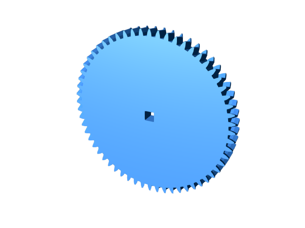
This gear is made to be compatible with Vex V5 Robotics. It is a helical gear with a .15" square hole in the middle for a shaft.
Helical Gear
38
0
0
James Dawson
James Dawson
UNITED STATES OF AMERICA
0
0
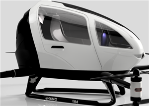
Project Overview This EHANG 184 drone model, inspired by EHANG, a leader in autonomous aerial vehicles, is a highly detailed, modular, and fully customizable 3D CAD project. I designed this drone enti...
EHANG 184 Fully Customizable 3D Drone Project – For Intermediate & Advanced CAD Users
52
0
2
Engineer
Engineer
GHANA
1
3
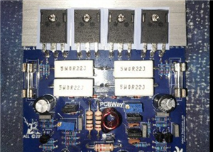
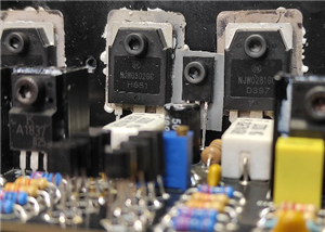
NOTE 1: This project is not intended for beginners. It is intended for someone with a medium understanding of electronics and electronic components and soldering skills. Do NOT attempt this as your fi...
150W Lateral MOSFET Power Amplifier
93
0
0
Astro's Electronics Lab
Astro's Electronics Lab
AUSTRALIA
31
67
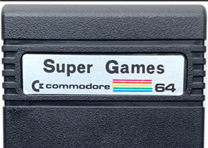
COMMODORE 64 SUPER GAMES CARTRIDGEHello,This is a tested and working PCB.This PCB is a reproduction of Commodore 64 Super Games Cartridge PCB.Commodore 64 Super Games Cartridge is an easy DIY project,...
COMMODORE 64 SUPER GAMES CARTRIDGE 1988
136
0
1
(DIY) C64iSTANBUL
(DIY) C64iSTANBUL
TURKEY
705
763
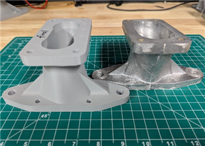
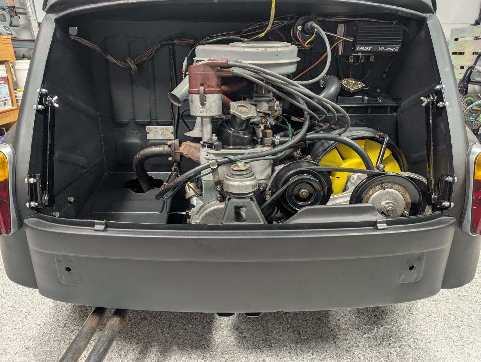
The engines in the Fiat 850 family of cars were slightly canted. In order to keep the carburetor level, they canted the intake manifold in the opposite direction. The engines in the Fiat 600s were l...
Performance intake manifold for the Fiat 850 engines in a Fiat 600-based car
62
0
0
MyFiat 600D
MyFiat 600D
UNITED STATES OF AMERICA
0
0
Build a 1kW 80V 30A WiFi MPPT Solar Charge Controller, equipped with a phone app datalogging telemetry! (available on Android & IoS) The design has been intensively tested for months and has been ...
DIY 1kW Open Source MPPT Solar Charge Controller
106671
83
156
Angelo Casimiro
Angelo Casimiro
JAPAN
465
0
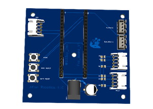
I use it for a FNAF Foxy head it has 2 sockets for LED Common(-) RGB LED's which are tied to operate together and 2 sockets for 2 Servo motors and its compatible with the raspberry pi pico board and i...
FNAF Head control board for raspberry pi pico WH
53
0
0
Sl33py Dev
Sl33py Dev
UNITED STATES OF AMERICA
0
0
UPDATE Jan 25, 2025:This design is now obsolete. Please use v1.8 instead which has far better transmit power and receive sensitivity, and fits more ESP32 dev boards! Find it here:kv4p HT v1.8a (1" wid...
kv4p HT v1.7b
27202
30
46
Vance Vagell
Vance Vagell
UNITED STATES OF AMERICA
47
0
This project is about a Commodore PLA replacement.PLA replacements for the Commodore 64 are available for quite a number of years and have grown increasingly sophisticated. Therefore you may ask why t...
Commodore 64 PLA replacement
27933
11
103
Daniël Mantione
Daniël Mantione
NETHERLANDS, THE
104
5
The QuinLED-Dig-Uno is a single channel ESP32 (v3 not suited for ESP8266) based addressable LED controller! Perfectly runs WLED or ESPixelstick firmware and easily integrates with MQTT and Home Assist...
QuinLED-Dig-Uno
52639
6
117
Quindor
Quindor
NETHERLANDS, THE
300
0
You've probably heard of FreeTocuhDeck. You haven't? Go check it out: https://www.youtube.com/watch?v=soIGV6BszcMWhen I was designing FreeTouchDeck, I quickly ran in to issues when using a breadboard....
ESP32 TFT Combiner V1
25875
14
29
Dustin Watts
Dustin Watts
NETHERLANDS, THE
50
4
The QuinLED-Dig-Quad is a Quad channel ESP32 (ESP8266 dropped since v3!) based addressable LED controller! Perfectly runs WLED or ESPixelstick firmware and easily integrates with MQTT and Home Assista...
QuinLED-Dig-Quad
29864
17
65
Quindor
Quindor
NETHERLANDS, THE
300
0
Amplificador de 200W RMS con transistores 2SC5200/2SA1943 (También admite las variables NJW0302G/NJW0281G)Se alimenta con una fuente simétrica de hasta +/-60VDC y trabaja con cargas entre 4 y 8 Ohms.C...
Amplificador 200W con 2SC5200 y 2SA1943
55
1
1
Cristian Castro
Cristian Castro
ARGENTINA
27
0
A Real Time Clock (RTC) that is hidden "under" the Boot ROM of the Model II(until access is enabled by special software) No need to sacrifice a slot of the TRS-80 Model II. Software to set and read th...
Real Time Clock for TRS-80 Model II using DS1215/DS1315
29
3
0
Ruud Broers
Ruud Broers
NETHERLANDS, THE
0
1
The Jeffrey 2.1 PCB for the iSpindel. Please head over to www.OpenSourceDistilling.com/iSpindel for an in depth description, parts list, instructions, and video tutorials. Minor improvements are compl...
iSpindel The Jeffrey 2.1 - Open Source Distilling
27091
0
39
Open Source Distilling
Open Source Distilling
CANADA
105
4
### DESCRIPTIONPCB for PETlng 122mm / d33mm for iSpindel project (electronic Hydrometer)https://github.com/universam1/iSpindel/blob/master/docs/README_en.md### TECHNICAL DETAILS / COMPONENTS- 1 Plasti...
iSpndel_4.0
51637
50
43
Filippo Ceraulo
Filippo Ceraulo
ITALY
88
1
1
2
3
4
5
6
7
8
9
10
11
...