


|
KiCad 9.0 |
|
|
|
FreeCADFree Software Foundation, Inc.
|
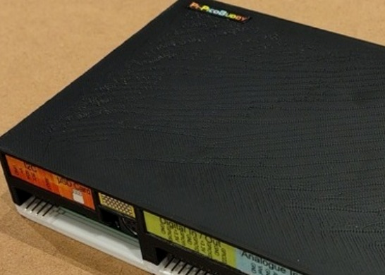
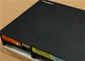
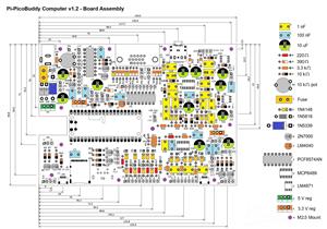
Pi-PicoBuddy Computer v1.2
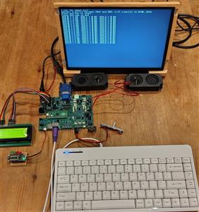
The Pi-PicoBuddy Computer project is a Boot-To-Basic computer in the same vein as the machines from the late 70’s/early 80’s, supporting the excellent PicoMite BASIC firmware for the Raspberry Pi Pico (https://geoffg.net/picomite.html).
The Pi-PicoBuddy Computer hardware project set out with the following design aims:
- Low-cost to build. The target was to be able to build a computer from a kit for the same price or less as the original ZX81 kit, £49.99. This meant using readily available components without relying on specialised or short life-expectancy parts. It also meant choosing as few different parts as possible, so that instead of buying twenty different values of resistor, the builder only needa to buy multiples of the same component to benefit from price breaks where possible.
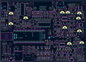
- Simple to build. The target was for a beginner to be able to build the Pi-PicoBuddy with only basic soldering tools and skills. It is as uncomplicated as I could make it (e.g. the design uses through-hole components wherever practical). The components are easily distinguishable (e.g. resistors avoid similar colour codes) and the orientation of polarised components is strictly controlled on the PCB to aid visual inspection.
- Multiple applications. The computer should support as many options for expansion as could be managed within the limits of the price constraint. It is partly inspired by the BBC Micro, which was designed to maximise its “usefulness” in real-world and educational settings by having a huge number (for the time) of interfaces pre-built-in.
- Flexible power options. The Pi-PicoBuddy is able to run from a variety of power sources. It also provides configurable internal supplies e.g. separate linear analogue power rails to minimise noise and EMI and to remove supply “hiss” when generating audio.
- The on-board additional hardware options either run from the stock PicoMite Basic firmware out-of-the-box, or through the use of simple BASIC routines that can be included in user’s programs (examples provided in the documentation)
The documentation .ZIP file contains schematic, BOM, assembly details, some simple code samples, enclosure CAD and label image files, and build drawings showing component positions and PSU jumper configurations.
PicoBuddy Computer specifications
- Based on the Raspberry Pi Pico 2040 microcontoller board running PicoMiteVGA Basic. Official Raspberry Pi Pico 2350 boards have also been tested and provide greater memory, speed and display modes.
- Powered supply options:
- +5 V connected to the Pico USB connector
- +5 V connected to the 2.1 mm barrel jack (reverse and over-voltage protection).
- >5V connected to the 2.1 mm barrel jack (reverse and over-voltage protection) using onboard regulator.
- Selection of onboard SMPS or linear regulators to optimise efficiency/noise
- 2 x I2C busses with STEMMA QT connectors and/or 4-pin headers. Each bus can be independently set to 5 V or 3.3 V operation
- PS/2 keyboard input (USB available with the USB-enabled versions of the PicoMite Basic firmware)
- Micro--SD card slot
- 5 x digital I/O
- 3 x buffered analogue-to-digital inputs, plus buffered 3.0 V reference supply
- Stereo PWM output to headphones, or to 8 Ohm speakers via class A/B amplifiers
- VGA output, two colour palettes
- Onboard HD4487-compatible LCD interface
- Onboard 8 x digital I/O
Have fun!
V1.2 Updates from V1.1
- JP7 idents corrected
- Edge connector pin idents moved so they are not obscured by right-angle headers
- Audio filter and analogue input buffer filter bypass points updated
- Q1-9 pad spacing increased to simplify soldering
Pi-PicoBuddy Computer v1.2
Project images are for reference only. Actual production is based on the manufacturing files on the project page.
Please review the designer's notes (e.g., PCB thickness) and select the appropriate options.
PCBWay is not responsible
for issues caused by unsuitable parameter selections.
For more important ordering information, please refer to
Read More


Raspberry Pi 5 7 Inch Touch Screen IPS 1024x600 HD LCD HDMI-compatible Display for RPI 4B 3B+ OPI 5 AIDA64 PC Secondary Screen(Without Speaker)
BUY NOW


- Comments(0)
- Likes(0)
 More by Dave C
-
Programmable Mist Maker - XIAO / QT PY Extension
1066 2 1 -
RadioHAT - Raspberry Pi radio development platform
878 0 2 -
-
-
-
-
ARPS-2 – Arduino-Compatible Robot Project Shield for Arduino UNO
3331 0 6 -
A Compact Charging Breakout Board For Waveshare ESP32-C3
3940 3 8 -
AI-driven LoRa & LLM-enabled Kiosk & Food Delivery System
4326 2 2


