


|
Hot PlateGeneric
|
|
|
DT71 Mini Digital TweezersAdafruit
|
|
|
|
PCBWAY |
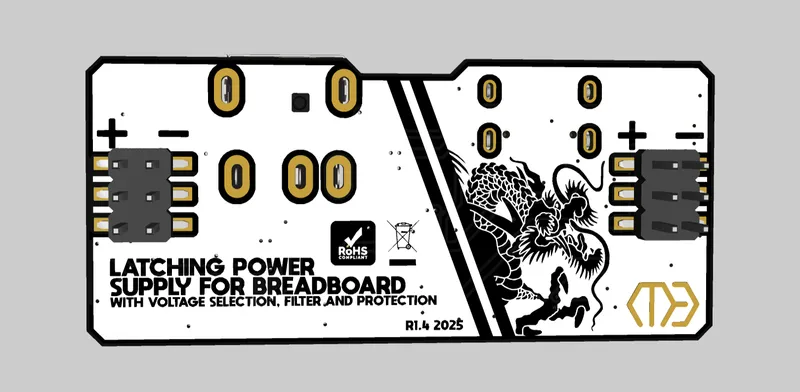
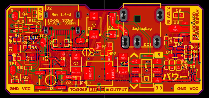
Over-Engineered Breadboard Power Supply Module
Video Overview:
Overview:
Thanks to PCBWay for sponsoring this project. (More about them later)
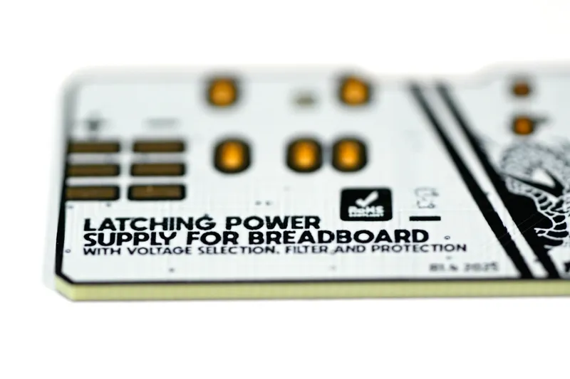
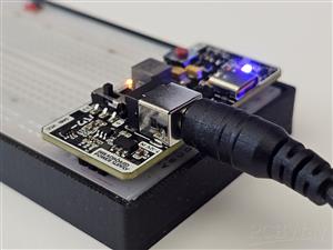
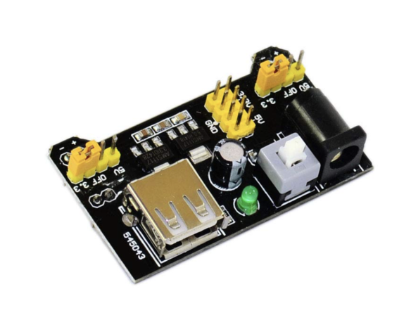
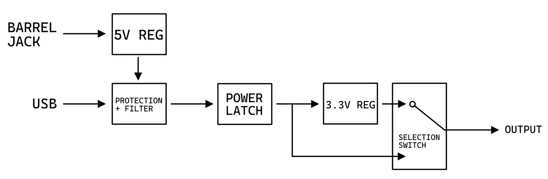
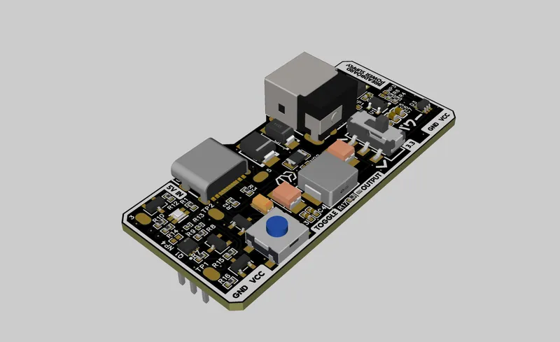
This project is a module that attaches to a standard breadboard and provides power. Unlike other commercial power modules, the one I have designed has lots of useful (and over-engineered) features.
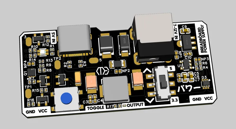
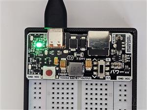
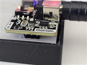
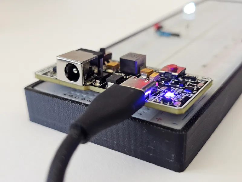
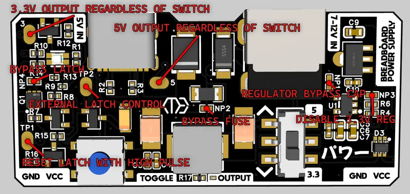
First of all, the power supply supports USBC input (without PD capabilities yet, maybe an idea for a V2.) which is important due to the popularity of USBC, and the phasing out of barrel jacks as power supply inputs. The board does still have a barrel jack as many users and education facilities still rely on barrel jacks rather than USBC.
The board also provides a low impedence output with minimal heat loss (except for voltage regulators due to the nature of their architecture) The resistance calculated from the USB port to the output was approximately 0.05-0.1 ohms† depending on current (about 1/8th of the resistance of a male-to-male jumper wire)
†as measured between the “5” test pad on the input and output pads on the bottom side. Fixed 5v input with variable load between 10mA to 1A. Resistance value may be different based on your fuse, pcb copper weight, pmos quality etc
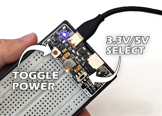
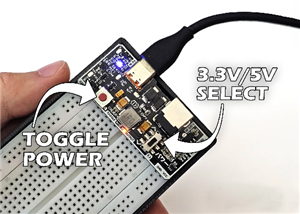
With regards to electronic features, there is a power latch which is achieved with a button and transistors instead of a mechanical latch, meaning this design will last a lot longer at the expense of higher cost. This latch is stable and does not oscilate, even when the button is held.
There is also a PTC fuse for limiting current, TVS diodes for ESD protection (and to prevent failed circuits from feeding back power in to the input).
There are two large SMA and SMB diodes on the PCB. One of which is in series with the barrel jack for polarity protection and for feedback protection, and the smaller diode is a crowbar diode. If power is reversed to the board, it is a failsafe in case everything else fails.
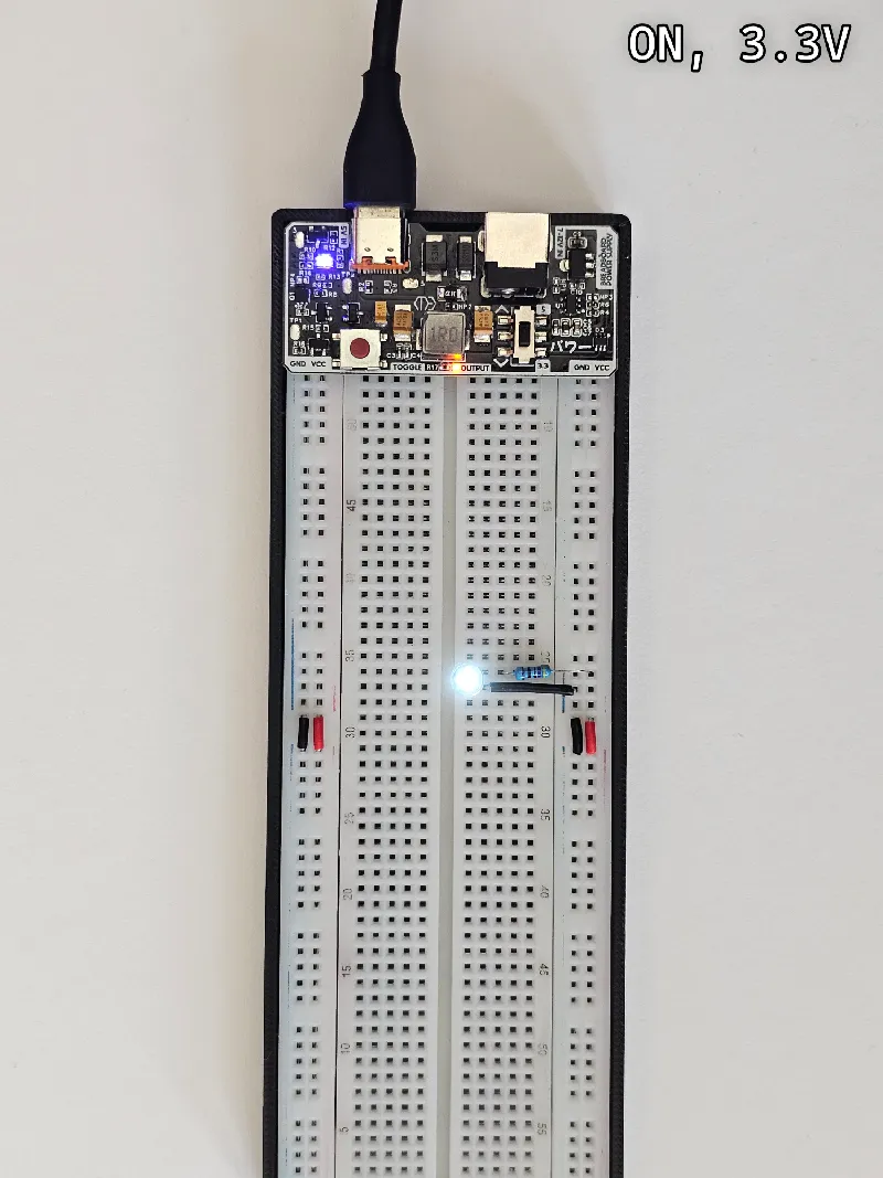
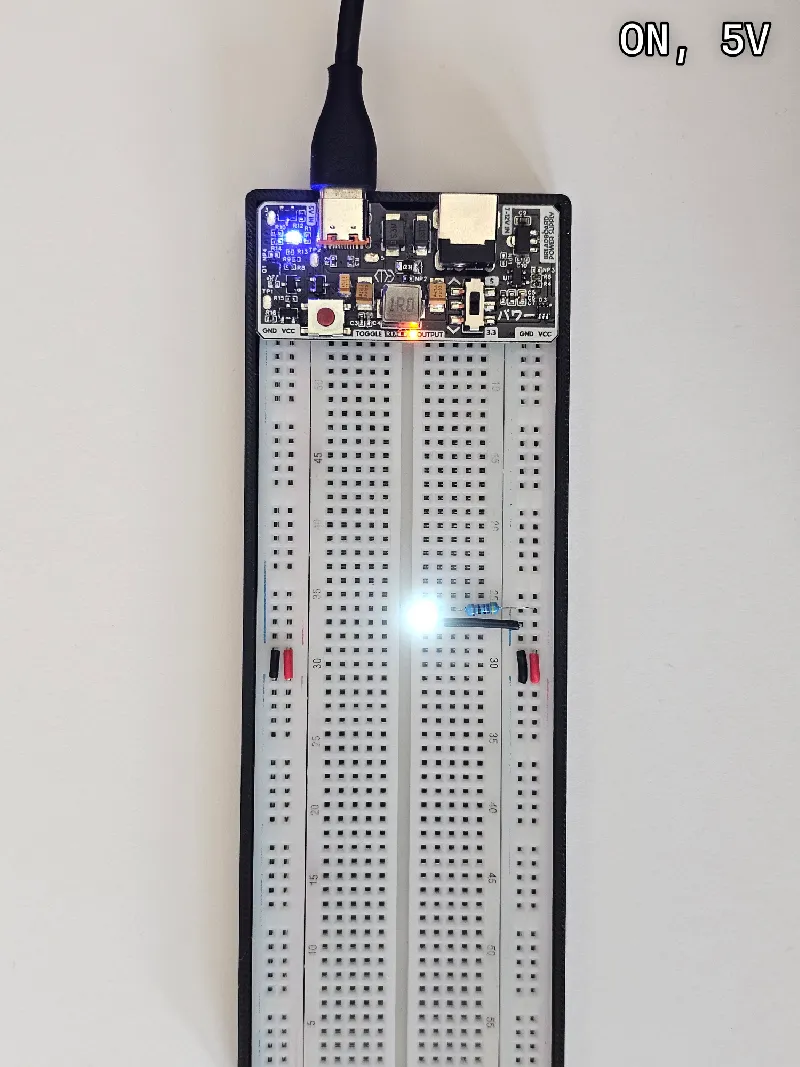
There is also an SMD slide switch on the board to easily change input power from 5v to 3.3v from an on-board regulator. (There is one 3.3v regulator, and another 5v regulator for the barrel jack)
The large inductor and capacitors on the front of the board act together to make a CLC filter to remove as much input noise as possible without increasing impedance a significant amount
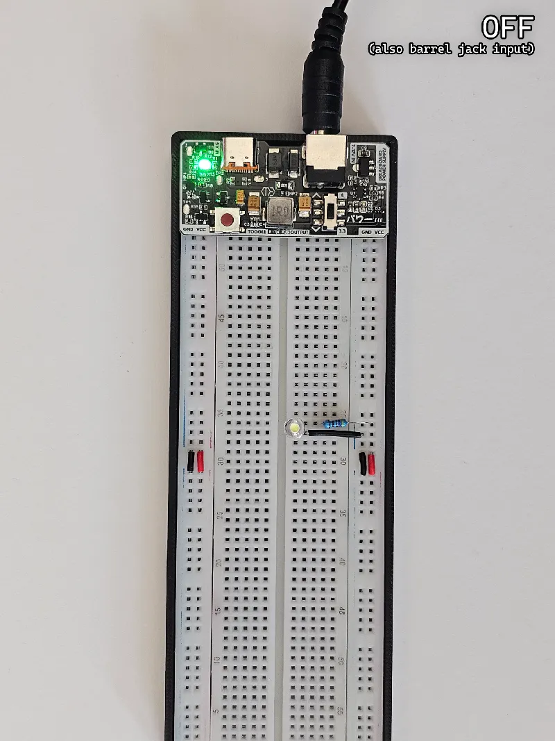
Finally, there is an RGB led that indicates:
- Power present from USB but none is being outputted
- Power present from USB and is being outputted
- Power present from barrel jack but none is being outputted*
- Power present from barrel jack and is being outputted*
*not present in my images because R14 should be 2.4k and not 10k like ive used.
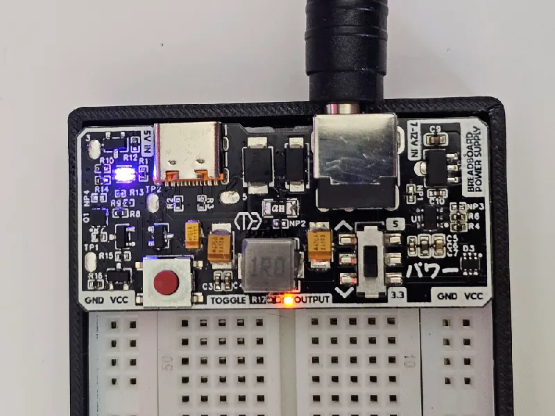
Another 0201 led is present at the base of the inductor which directly connects to the output to check for power. It changes brightness when the mode is being switched from 5v to 3.3v, and can be used for double checking power output in troubleshooting scenarios.
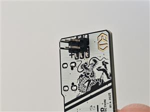
Finally, the headers at the base are SMD and not TH, which makes them able to slide in and out slightly before soldering. This makes adjustability makes this more compatible with breadboards that have different manufacturing tolerances.
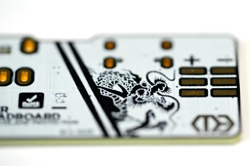
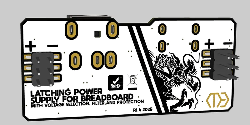
There is also a nice silkscreen design which I don't see many people doing
Caution: This project involves soldering mostly 0402 components with some 0201s. A hotplate (or reflow oven) is required. The overall difficulty of assembly is 4/5.

Basic Diagram
Solder Bridges and Pads:
Maximum Currents:
3.3V regulator: 350mA (unless your chosen regulator is different. check datasheets)
5V regulator: 300mA (unless your chosen regulator is different. check datasheets)
Fuse: Up to you to decide. If you are planning to use the regulators a lot, pick a 300mA one. If you will primarily be using 5v through the USB, Pick 1A.
The latch and other protection features do not have a noteworthy current limit. I'd say 10A+ is fine
Assembly:
BOM is listed later in the guide. Order Gerber files from PCBWay. Stencil not mandatory, but it would help with assembly ($10 extra for stencil). Also order components according to BOM
Useful files for this step: Gerber_BreadboardPSU.zip
Apply solder paste to the top side and place components. “NP” components and test pads do not need solder. Check polarity of diodes and tantalum capacitors. D3 can be placed in both directions but the RGB and Q1 will only work in one orientation.
Useful files for this step: Labelled assembly helper image.zip
Use a hotplate or reflow oven to solder the components on to the board. Check if components are in the correct position and make sure there aren't any shorts. The components most susceptible to shorts are Q1, the USB port, and any 0201 components. If there are, use flux and solder wick to remove excess solder. If a component is misaligned, use tweezers and a hot air gun to reposition it.
Do one final check for shorts and move on to the bottom side. These SMD pins can be soldered with a soldering iron and solder wire.
Clean PCB with an ultrasonic cleaner (use distilled water and let FULLY dry), or isopropyl alcohol and a toothbrush/1cm^3 cleaning sponges.
Test the board and enjoy!
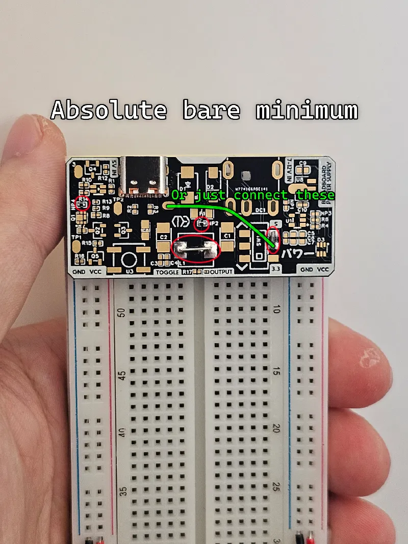
Note: you do not need to install all components for use. You can use the "NP" jumpers to bypass certain elements of the PCB which you may not want (or have). Q5 and R16 can both be removed if you aren't planning of using the pad on the bottom left - “reset latch with high pulse”. R13 is also not very important, as its only used for stability.
Useful files: BreadboardPSU Schematic.pdf
 (this works… but i wouldnt recommend it)
More EDA images:
BOM:
Simplified BOM:
47uF Case-B Tantalum Capacitor x2 C1,C2
100nF 0402 Ceramic Capacitor x4 C3,C4,C5,C10
1uF 0603 Ceramic Capacitor x3 C6,C7,C9
22uF Case-A Tantalum Capacitor x1 C8
S3MB Diode, SMB Package x1 D1
SS110 Diode, SMA Package x1 D2
SMF05CT1G, SOT-363 Package x1 D3
DC-044A Barrel Jack x1 DC1
PTC Fuse 1206 (choose 300mA to 1A) x1 F1
1uH 0650 Inductor (L7-W6.6) x1 L1
RGB Led 0606, common cathode x1 LED1
Led, orange 0201 x1 LED2
0402 Ceramic capacitor (not populated) x1 NP1
0402 Resistor (not populated) x3 NP2,NP3,NP4
0 Ohm resistor (shunt) 0402 x3 R4,R6,R15
CSD25310Q2 P-channel MOSFET x1 Q1
BC817 NPN (SOT-23-3) x4 Q,Q3,Q4,Q5
1K Ohm Resistor 0402 x5 R1,R10,R12,R16,R17
5.1K Ohm Resistor 0402 x2 R2,R3
10K Ohm Resistor 0402 x1 R14
100K Ohm Resistor 0402 x2 R7,R8
680K Ohm Resistor 0402 x2 R9,R13
MST22D18G2 Slide switch x1 SW1
MIC5205-3.3YM5 3.3V LDO SOT-23-5 x1 U1
16 Pin USBC Port x1 U2
~6*6mm SMD Button x1 U3
2.54mm Pitch, 2x3 SMD Headers, Male x2 U6,U7
78S05M 5V LDO SOT-89-3. 350mA!!! x1 U8
Extra Notes:
The red light was incredibly dim on the RGB led after assembly. Please change R14 to 2.4k ohms.
I am actually using two different PCBs in this project, “Rev-1.4c” and Rev "1.4d". I mesed up the connection to R9 in the c version but it was too late, and the manufacturing had already started. I ordered a revision d but only in the HASL surface finish. The gerber files and schematic are all of the functional board.
This project is not possible with hand soldering. You must have a hot plate, or a reflow oven.
Some components are “missing” designators (like U8) as the label is located underneath the component.
If you use a higher value for C8, you may need to press the toggle button for a slighly longer period of time to get the latch to activate
Thanks to PCBWay for partially funding another project by providing the PCBs for free. PCBWay is a company that I genuinely use even outside of sponsorships as I can guarantee quality. Feel free to check out their prototyping or even advanced PCB manufacturing here: https://www.pcbway.com They also offer other manufacturing services that I have used in the past such as CNC machining, 3D Printing, sheet metal and injection moulding.
My experience with PCBWay has always been great, including their product quality and responsive customer service. What makes PCBWay stand out over their competitors (and makes it my go-to) is that you recieve a price quote before payment. This is invaluable as you actually know what you're going to pay, and wont experience post-order price spikes.
Ordering this PCB would cost about $40 with the gold (ENIG) finish, and approx $5 with the default HASL.
Sponsorships like this help fund more ambitious projects like this - make sure to check out their services :)
Please consider supporting this project by purchasing through Printables: https://www.printables.com/model/1379084-breadboard-power-supply-module
Over-Engineered Breadboard Power Supply Module
Project images are for reference only. Actual production is based on the manufacturing files on the project page.
Please review the designer's notes (e.g., PCB thickness) and select the appropriate options.
PCBWay is not responsible
for issues caused by unsuitable parameter selections.
For more important ordering information, please refer to
Read More


Raspberry Pi 5 7 Inch Touch Screen IPS 1024x600 HD LCD HDMI-compatible Display for RPI 4B 3B+ OPI 5 AIDA64 PC Secondary Screen(Without Speaker)
BUY NOW

- Comments(3)
- Likes(7)
 More by Magma bow

-
Programmable Mist Maker - XIAO / QT PY Extension
1067 2 1 -
RadioHAT - Raspberry Pi radio development platform
882 0 2 -
-
-
-
-
ARPS-2 – Arduino-Compatible Robot Project Shield for Arduino UNO
3332 0 6 -
A Compact Charging Breakout Board For Waveshare ESP32-C3
3941 3 8 -
AI-driven LoRa & LLM-enabled Kiosk & Food Delivery System
4326 2 2


