



|
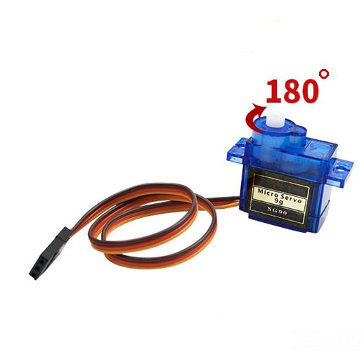
SG90 Micro Servo motors |
x 4 | |
|
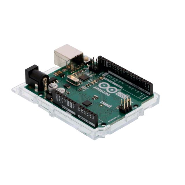
A000073Arduino
|
x 1 | |
|
|
motor shield |
x 1 | |
|
|
mearm printable parts |
x 1 |
MeArm PickPlace
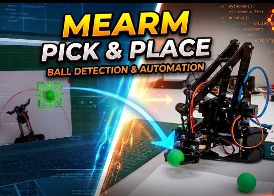
The project involves the development of an autonomous robotic system based on a 4DOF arm with a parallelogram structure (MeArm). The system is capable of identifying objects (colored balls) on a workspace using a webcam, calculating their real coordinates in millimeters, and commanding the robotic arm to grab and deposit them into a predefined 'drop zone'. The software is written in Python and communicates with a microcontroller (Arduino R3) via Serial or Bluetooth Low Energy BT-24 module.
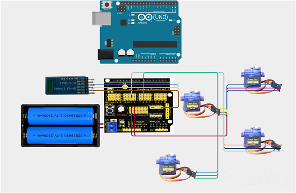
Wiring (-> motorshield pins)
| Servo | Funzione | Pin |
| 1 | Base | A1 |
| 2 | Shoulder | A0 |
| 3 | Elbow | 6 |
| 4 | Gripper | 9 |
| 5 | BT Module | v,g,rx,tx |
SOFTWARE
CALIBRATE_COLOR.PY
Opens the webcam with trackbars to find the correct min/max HSV values for your ball's color, under your lighting conditions. Move the trackbars until only the ball appears white in the "Mask" window (everything else black), then copy the values printed in the console into config.COLOR_RANGES. The values will be printed in the console after pressing 'q'.
CALIBRATE.PY
Camera -> table calibration via 4-point homography.
INSTRUCTIONS:
Fix the camera above the table, framing the arm's entire workspace (top-down view; it is fine if it is not perfectly perpendicular, the software will adjust it automatically). Place 4 markers at 4 points where you know the REAL coordinates in mm relative to the arm's base (measure them with a ruler: x = left/right of the base, y = forward from the base).Run this script, click the 4 points on the image IN THE SAME ORDER you defined them below in REAL_POINTS_MM, then press 's' to save (for example, I defined them clockwise: top-left -> top-right -> bottom-right -> bottom-left).
SCAN_BLE.PY
Diagnostic script to understand how to communicate with the BT-24 module via BLE.
INSTRUCTIONS:
Run python scan_ble.py. It will show all BLE devices found nearby (name + address). Identify the one for the arm (it is probably named "DX-BT24" or "BT24").It will show all BLE devices found nearby (name + address).
Identify the one for the arm (it is probably named "DX-BT24" or "BT24").
Run the script again, passing the address as an argument:
- python scan_ble.py AA:BB:CC:DD:EE:FF (Windows/Linux)
- python scan_ble.py 44BAD4C8-18F8-FAE0-ED97-FFFC3A69A296 (macOS uses UUID instead of MAC)
It will connect and print ALL services and characteristics, along with their respective properties (read/write/notify).
What to look for in the result of this step:
- A characteristic with "write" or "write-without-response" properties -> this is the one the PC writes to in order to SEND data to the arm (equivalent to PC TX / module RX).
- A characteristic with the "notify" property -> this is the one the module uses to NOTIFY data to the PC (equivalent to module TX / PC RX), useful for reading "OK"/"ERR" ACKs.
Note down the UUIDs of these two characteristics: you will need them for config.py (BLE_WRITE_CHAR_UUID and BLE_NOTIFY_CHAR_UUID) and to create ble_link.py.
Many inexpensive modules of this type use a SINGLE characteristic for both writing and notifying (e.g., a UUID ending in "FFE1"): if you see a single characteristic with BOTH write+notify properties, use it for both directions.
MAIN
Multithreading + Semicircular Trajectory. The main thread handles smooth 30fps video. The secondary thread moves the arm using predetermined safe angles (you need to upload arduino sketch on the board and decide if communicate via serial or bluetooth in Config.PY).
Problem Solving
Mechanical limitations of Inverse Kinematics
The `kinematics.py` file contains the mathematical implementation of inverse kinematics used to calculate shoulder and elbow angles based on X, Y, and Z coordinates. However, testing (via the interactive `test_kinematics.py` script) revealed limitations inherent to the arm's parallelogram structure:
Irregular workspace: Extending the Y-axis too far forward (beyond 110 mm) drastically reduced the maximum height (Z) the arm could reach, causing the motors to stall.
Gripper orientation: Due to the lack of a dedicated wrist motor, excessive extension caused the gripper to tilt at an angle, making it impossible to grasp objects.
Solution: Fixed semi-circular operating radius. By bypassing the mathematical constraints through a geometric approach, it became possible to define an optimal, fixed operating radius around the robot, within which the gripper descends in a perfectly perpendicular orientation. In the main program, only the base angle is calculated using the arctangent of the coordinates (`math.atan2(x_mm, y_mm)`). The shoulder and elbow angles are no longer calculated dynamically; instead, they are set to pre-calibrated, safe values:
- Travel height: Shoulder 90°, Elbow 90°.
- Pick height: Shoulder 93°, Elbow 60°. In this configuration, the robot rotates toward the target and arrives at the designated semi-circular operating path. Multithreading
Initially, using commands like `time.)` to allow the servomotors the physical time required to reach their positions caused the OpenCV video stream to freeze, effectively rendering the camera "blind" during movements.
Solution: Message Queue. The `main.py` file implements the `threading` module.
The Main Thread handles the OpenCV video loop at a constant 30 FPS, processes homography, and tracks colors.
The Worker Thread remains in a waiting state. When the main thread identifies a target, it places the (X, Y) coordinates into a `queue.Queue`. The worker thread retrieves these coordinates, sets a flag (`is_busy.set()`) to prevent further inputs from the camera, and then executes the mechanical movement.
Conclusion
The project demonstrates the integration of an advanced computer vision system with low-cost hardware control. The inherent limitations of the budget-friendly mechanical components have been fully compensated for through rigorous software design and a practical approach to the system's geometry, resulting in a reliable, autonomous, and smooth-moving robot.
MeArm PickPlace


Raspberry Pi 5 7 Inch Touch Screen IPS 1024x600 HD LCD HDMI-compatible Display for RPI 4B 3B+ OPI 5 AIDA64 PC Secondary Screen(Without Speaker)
BUY NOW


- Comments(0)
- Likes(1)
More by Luca Fagioli
-
 MeArm Connect4 Simulation
The project consists of the development of an end-to-end physics simulator of a robotic arm (MeArm) ...
-
 MeArm Hand Gesture Control
A webcam watches your hands. Python (using mediapipe) tracks the landmarks of both hands in real-tim...
-
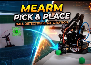 MeArm PickPlace
The project involves the development of an autonomous robotic system based on a 4DOF arm with a para...
-
 MeArm-ML-PyBullet
A 4DOF trained in simulation using reinforcement learning to reach a target, and transferred via ser...
-
 TrisVision MeArm
The project consists of the development of an interactive robotic system based on a 4DOF arm with a ...
-
 4WD SLAM Radar 2D Robot Car
An autonomous 4-wheel drive explorer robot based on Arduino UNO R4 WiFi , designed to navigate throu...
-
-
-
AudioLink – USB & Bluetooth LE Audio / Auracast Receiver with Balanced Line Outputs (nRF5340)
278 0 1 -
-
-
-
Émetteur Récepteur Optique Expérimental (communication UART ATtiny + fibre optique)
357 0 1 -
SmallOLED - Live PC Stats, Animated Clocks & Audio Visualizer
1428 0 3 -
"Talking Multimeter": Arduino-Based Speech Add-on for Multimeters with SCPI Protocol
797 0 1