





|
arduino IDEArduino
|
|

|
VS Code |
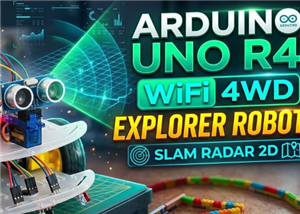
4WD SLAM Radar 2D Robot Car
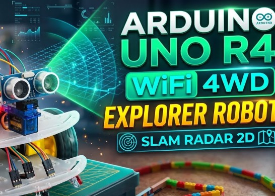
An autonomous 4-wheel drive explorer robot based on Arduino UNO R4 WiFi , designed to navigate through paths and mazes while detecting surrounding obstacles. The robot performs 180° radar scans via an ultrasonic sensor mounted on a servo motor and transmits real-time telemetry via Wi-Fi ( Simultaneous Localization and Mapping) to an interactive Web dashboard, which reconstructs the 2D vector map of the surrounding walls.
3D MODEL --> view
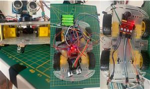
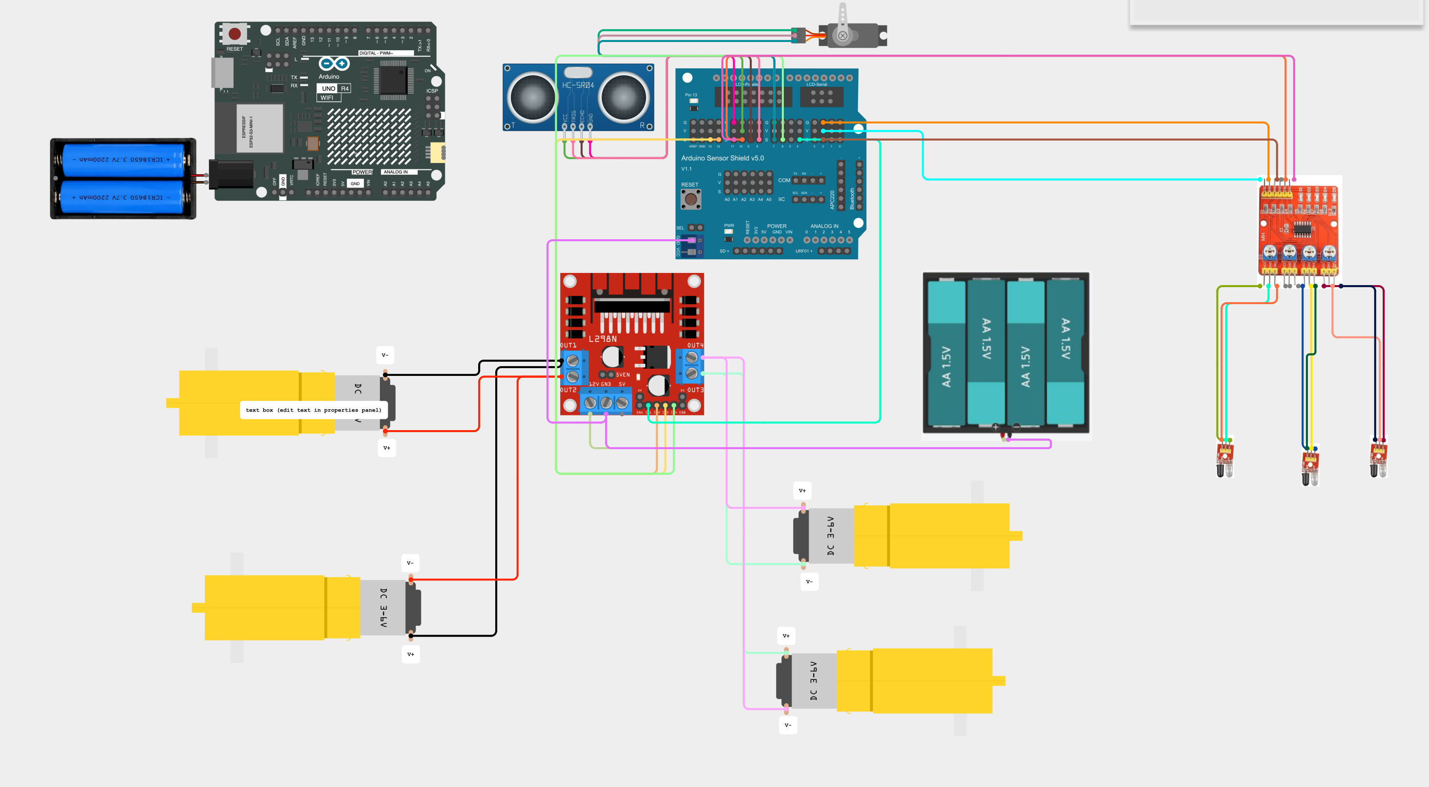
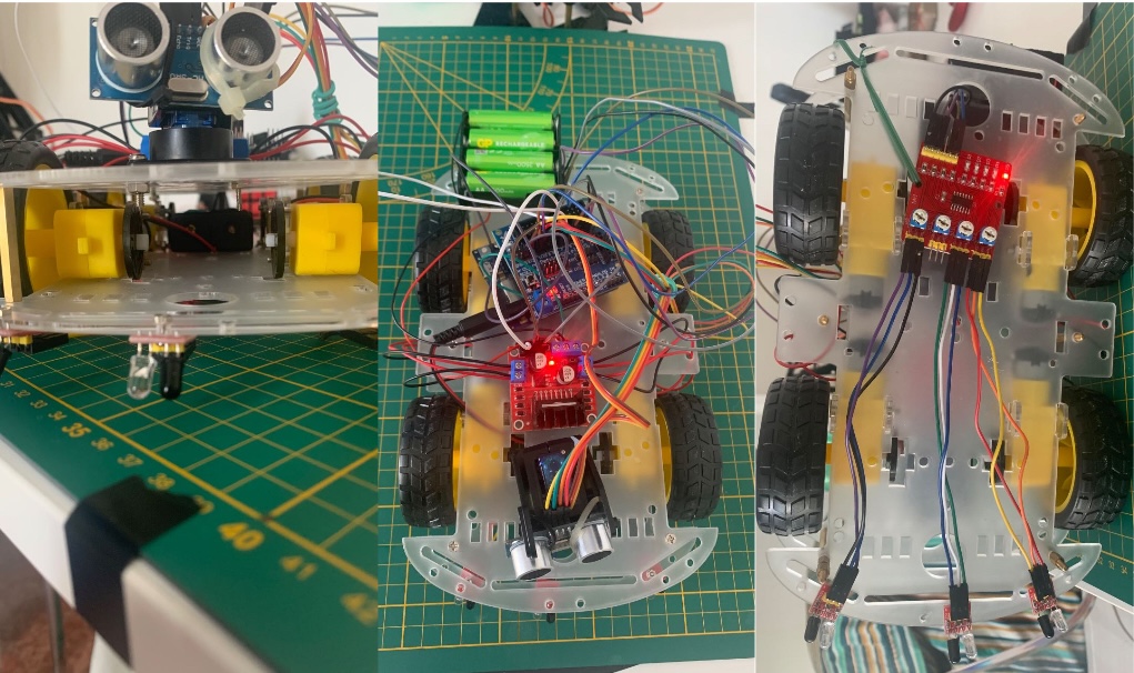
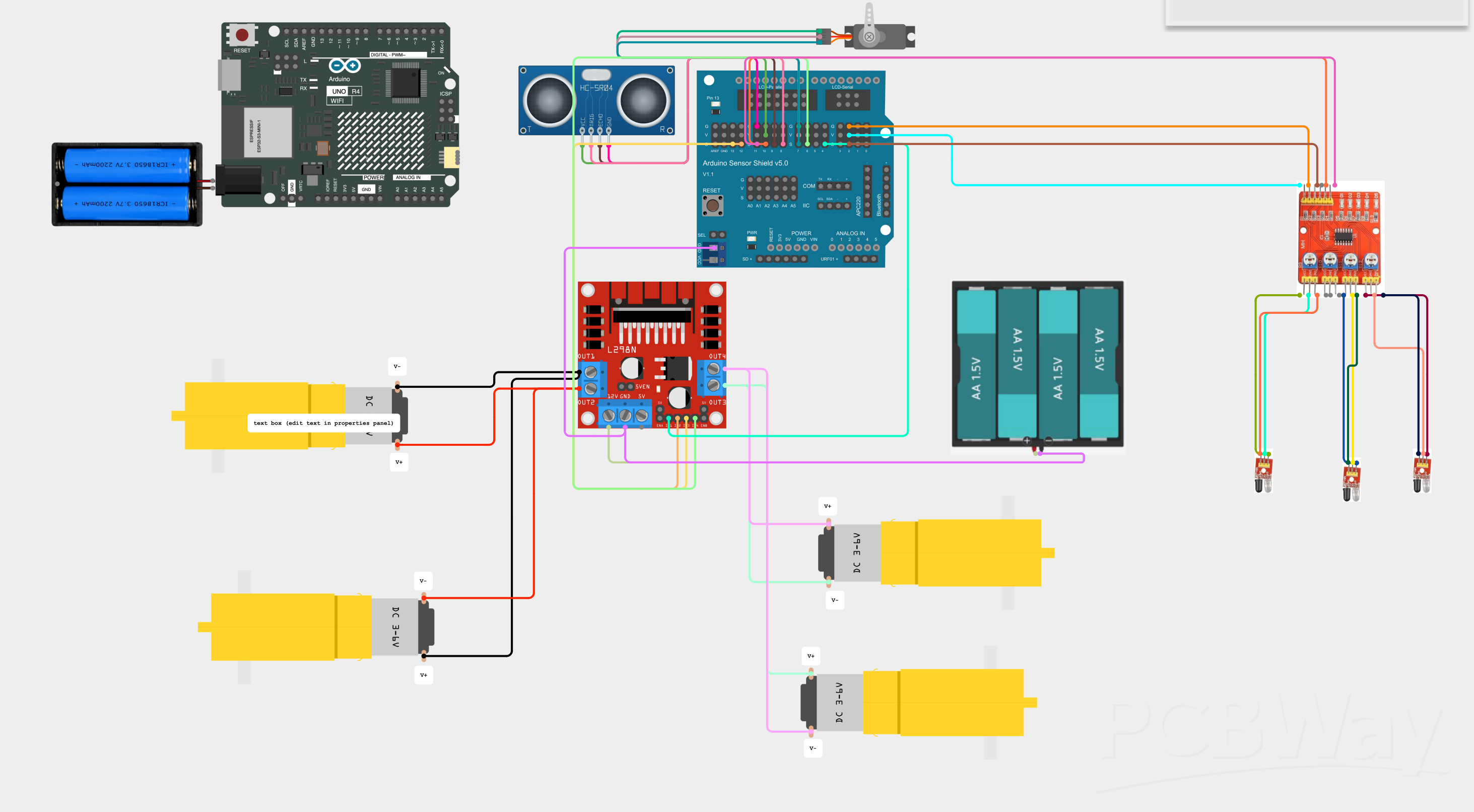
Wiring and Hardware
Microcontroller : Arduino UNO R4 WiFi + Sensor Shield V5.0
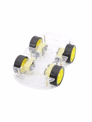
Chassis & Motors: 4WD Chassis with 4 DC TT gear motors (yellow)
Motor Driver: H-Bridge module L298N (with jumpers inserted on `ENA` and `ENB` to deliver 100% power)
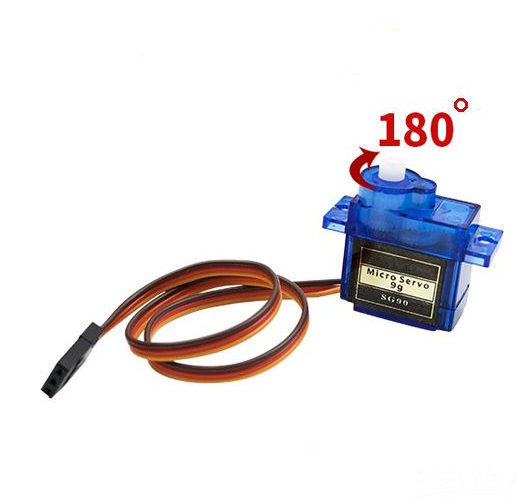
Radar Turret: HC-SR04 ultrasonic sensor mounted on an SG90 micro-servo motor
Waypoint Odometry: Module with 3 Infrared (IR) Sensors positioned under the chassis for detecting configurable checkpoints (black tape at fixed intervals on the floor)
Separate Dual Power Supply:
Logic (Arduino, Wi-Fi, Sensors, Servo): Battery pack with 2 Li-Ion 18650 cells (7.4V – 8.4V) connected to the Arduino R4 Barrel Jack.
Power (4 DC Motors): 4x AA battery holder connected to the 12V/VMS and GND terminals of the L298N driver (with shared `GND` reference with the Sensor Shield and the `+5V` line disconnected to isolate the two circuits).
Pin Map on Sensor Shield
| Component | Module Pin | Arduino Pin (Sensor Shield) | Function |
| L298N Driver | `IN1` | Pin 4 | Left Motor Direction 1 |
| L298N Driver | `IN2` | Pin 12 | Left Motor Direction 2 |
| L298N Driver | `IN3` | Pin 13 | Right Motor Direction 1 |
| L298N Driver| `IN4` | Pin 6 | Right Motor Direction 2 |
| L298N Driver | `ENA` / `ENB` | *Black Jumpers* | Permanent 100% power enable |
| SG90 Servo | VCC/GND/Signal | Column 7 | Radar turret rotation (`5°` – `175°`) |
| HC-SR04 | `TRIG` | Pin 8 | Ultrasonic trigger pulse |
| HC-SR04 | `ECHO` | Pin 9 | Ultrasonic echo return reading |
| IR Sensors | `IR_SX` (`IN1`) | Pin 2 | Left IR Sensor (black tape reading) |
| IR Sensors | `IR_CENTRO` (`IN3`) | Pin 10 | Center IR Sensor (black tape reading) |
| IR Sensors | `IR_DX` (`IN4`) | Pin 11 | Right IR Sensor (black tape reading) |
Instructions for Use
Uploading the Arduino Sketch
1 - Open the `4wd.ino` file in the Arduino IDE.
2 - Enter your Wi-Fi network name (`ssid`) and password (`password`) in the first lines of the code.
3 - Connect the Arduino R4 WiFi to your computer via USB-C cable and upload the sketch to the board.
Obtaining the IP Address from the Serial Monitor
1 - Once the upload is complete, open the Arduino IDE Serial Monitor and set the baud rate to `115200 baud`.
2 - Wait a few seconds until the Arduino connects to the Wi-Fi router.
3 - Copy the local IP address printed on the screen in the monitor.
4 - Disconnect the USB cable and turn on the batteries (18650 pack on Arduino + 4xAA pack on motors).
Opening the HTML Web Interface
1 - Open the `map.html` file directly in your PC/Mac browser.
*(Note for Safari users on Mac: from the top menu `Develop`, enable "Disable Local File Restrictions" to allow the local page to communicate via HTTP with the robot's IP, or use Google Chrome).*
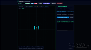
2 - In the top-left bar of the web page, paste the robot's IP address into the text box and click "Connect Wi-Fi".
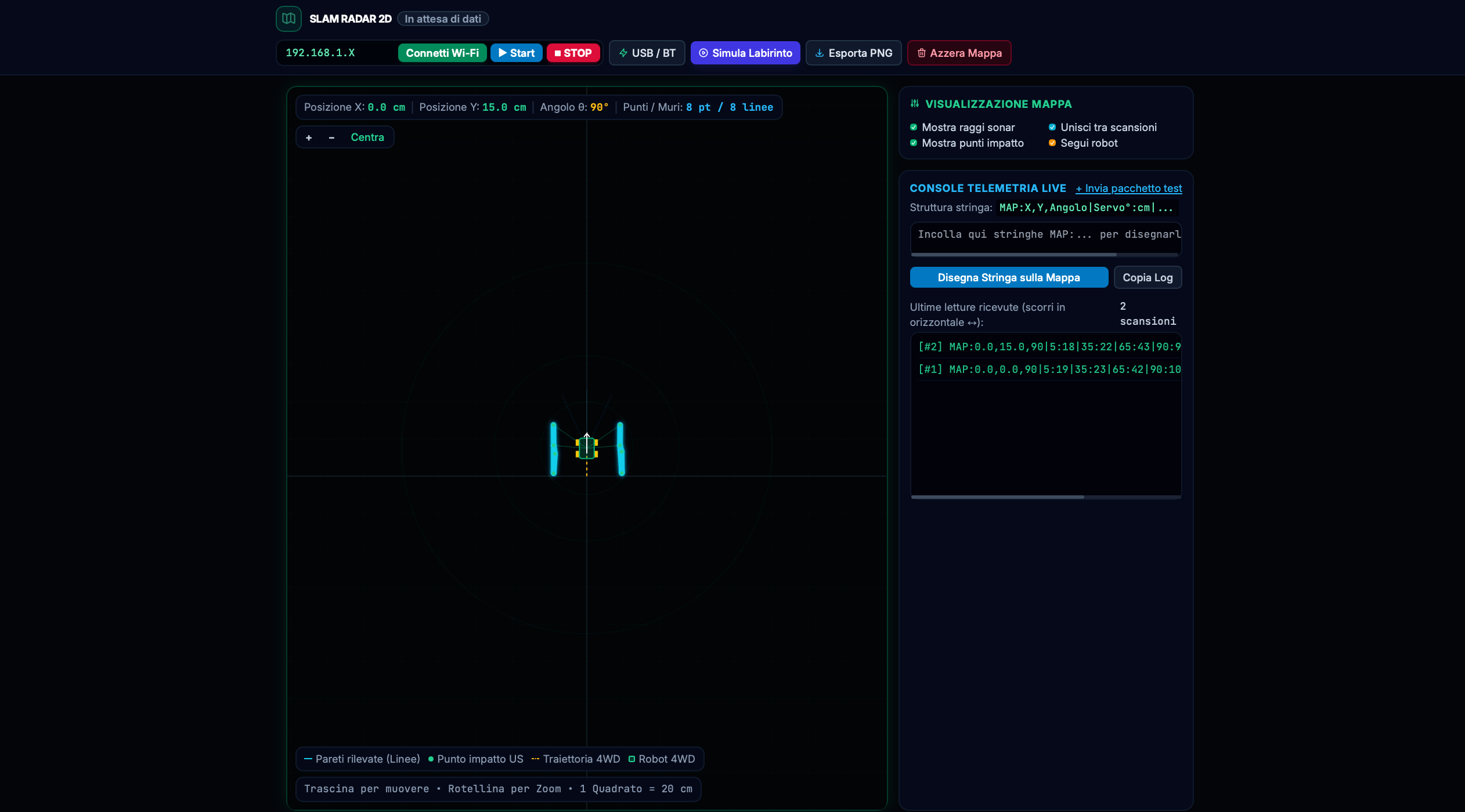
Starting and Stopping Exploration
* Click the light blue `▶ Start` button in the top bar to command the robot to begin scanning and autonomous path exploration.
* Click the red `⏹ STOP` button to instantly interrupt motor movement and pause the robot.
Operating Cycle
Navigation and Mapping Logic
The robot's operating cycle consists of 4 synchronized phases:
1 - 7-Angle Radar Scan:
While stationary, the robot rotates the SG90 servo motor across 7 angles distributed along the entire front arc (`5°`, `35°`, `65°`, `90°`, `115°`, `145°`, `175°`). At each step, it measures the distance in centimeters using the ultrasonic sensor.
2 - Free Navigation with Ultrasonic Emergency Brake
The robot moves using short timed bursts in free space. During travel, ultra-fast monitoring continuously queries the HC-SR04: if a wall drops below 13 cm, the robot brakes instantly to avoid collisions.
3 - Anti-Double-Scan Disengagement Maneuver:
If a close front obstacle is detected, the robot reverses by `4.5 cm` (subtracting the displacement from odometry coordinates), inspects the two extremes (`5°` far right and `175°` far left), and rotates toward the freer side. To avoid redrawing the same wall twice by overlapping lines, the software inhibits sending new scans until the robot has completed a new effective forward step.
4 - Final Target Detection
The IR sensors passively monitor the floor. As soon as they intercept the single end-of-course black tape, the robot stops the motors, notifies completion, and transmits the target signal to the dashboard.
Automatic Trajectory Cleaning (In-browser Ray Casting):
The web dashboard tracks the robot's trail and automatically removes all impact points recorded within a 9 cm radius of the passage, ensuring a central space perfectly clear of phantom points or spurious artifacts, cleanly and continuously highlighting only the outer perimeter walls of the route.
`MAP` Packet Format
The web dashboard cyclically queries the HTTP endpoint `http://<ROBOT_IP>/map` (equipped with CORS header `Access-Control-Allow-Origin: *`). The robot responds with a formatted string:
counter#MAP:posX,posY,thetaAngle|ang1:dist1|ang2:dist2|ang3:dist3|ang4:dist4|ang5:dist5|ang6:dist6|ang7:dist7
Example: 1#MAP:0.0,15.0,90.0|5:14|35:20|65:44|90:57|115:37|145:17|175:160.0, 15.0, 90.0:
The robot is located at X = 0.0 cm, Y = 15.0 cm and heading 90°.5:14... 90:57... 175:16: At various servo angles (from right to left), the sonar detected side walls at 14 cm and 16 cm and the free corridor ahead at 57 cm.
The HTML interface converts each (servoAngle, distance) pair into global Cartesian coordinates using trigonometry (cos and sin), drawing green impact points and connecting them with cyan vector segments.
Issues Encountered
1 - Voltage Drop on Motor Startup (Brownout Reset) : Powering the Arduino R4 WiFi (via the L298N driver's internal 5V regulator) and the 4 DC motors with a 4x 1.5V battery pack caused the current peak required by the simultaneous start of all 4 wheels to drop the voltage below the critical threshold, causing sudden Arduino reboots and loss of Wi-Fi connection right after the first servo scan.
Solution : Physical separation of power supplies using 2 Li-Ion 18650 batteries on the Arduino jack for logic/Wi-Fi only, and 4 AA batteries dedicated exclusively to the L298N board (maintaining only a shared GND reference).
2 - Hardware Conflict Between <Servo.h> Library and PWM (analogWrite) : Using the <Servo.h> library occupies the microcontroller's internal timers, interfering with PWM signal generation on Pin 3 (ENA) and leaving the left-side wheels without traction.
Solution : Re-inserting the physical jumpers on ENA and ENB directly on the L298N board, ensuring maximum motor torque via hardware to move the extra weight of the 18650 batteries and freeing up two digital pins.
3 - Wi-Fi STOP Command Latency: Using the blocking delay() function during motor advancement made the Arduino temporarily "deaf" to HTTP stop requests sent by the user.
Solution : Replacing all delay() calls with a custom asynchronous function (attendiConWiFi()) based on millis(), which queries the Wi-Fi server every 5 milliseconds even while the wheels are spinning, guaranteeing instant motor braking upon pressing the STOP button.
4 - Prevention of -360° Phase Shift and HC-SR04 False Echo Filtering: In very narrow corridors, the ultrasonic sensor occasionally returned instant false echoes below 4 cm (sound bounces off the floor or vibrations), trapping the robot in a continuous loop of reversals and rotations without sending data to the web page, accumulating incorrect phase shifts of the theta angle.
Solution: Implementation in the sketch of a double-filtered HC-SR04 data verification (which discards false zeros and requires consecutive confirmation before confirming an obstacle) and continuous normalization of the heading angle between 0° and 360°.
5 - Elimination of "Ghost Walls" in the Middle of the Road (Anti-Crossing Algorithm): Sequentially connecting all scan points (from right to left) caused the HTML interface to draw "V" shaped lines or cross segments cutting through the corridor traversed by the robot.
Solution :
Trajectory Cleaning (Free Space Mapping): The dashboard tracks the robot's trail and automatically removes all scan points recorded in the immediate vicinity of the passage (9 cm radius), since the space the robot passed through is free by definition.
Rigorous Right/Left Separation: The segment merging algorithm (computeWallSegments) prohibits connecting points belonging to opposite sides relative to the 90° central axis. Right points merge only with right points, and left points only with left points, preventing center crossover. If a scan temporarily loses contact with the side wall, the software automatically stitches the wall back by connecting to the first valid point in subsequent scans,geometrically verifying that the generated segment never intersects the yellow robot-traversed trajectory.
6 - Coordinate Freezing in Case of Jamming (Anti-Drift): If the robot got stuck in a corner spinning back and forth,open-loop odometry continued accumulating positive coordinates on the map, making the robot appear moving on the monitor while actually stationary.
Solution : Introduction of a minimum safety threshold on steps: if the robot makes a forward burst but is stopped by the emergency brake before traveling at least 6 actual centimeters, the software freezes the update of (X, Y)coordinates, preventing map drift.
7 - Directional Memory in Curves (Anti-U-Turn): When navigating tight hairpin turns requiring multiple consecutive rotation steps, the robot re-evaluated right/left midway through the maneuver. Being partially rotated, the sensor at the extremes (5° or 175°) ended up framing the free corridor just traversed behind it, tricking the driving logic and causing the robot to reverse direction back toward the start.
Solution: Introduction of a state variable with directional memory (direzioneInCorso). Upon detecting a front obstacle,the robot performs a single reversal, evaluates opening by combining the extremes (5° and 175°) with the diagonals (35° and 145°), and locks the chosen choice in memory. In subsequent steps, until the front view (90°, 65° and 115°) is completely clear again, the robot is constrained to continue rotating in place exclusively in the predetermined direction without further reversals or second thoughts, resetting memory only once entering a clear lane.
Conclusions
The project demonstrates how, even without LiDAR sensors or optical wheel encoders, it is possible to build a 2D SLAM system to successfully map close-range paths and control the robot safely from any web browser.
4WD SLAM Radar 2D Robot Car


Raspberry Pi 5 7 Inch Touch Screen IPS 1024x600 HD LCD HDMI-compatible Display for RPI 4B 3B+ OPI 5 AIDA64 PC Secondary Screen(Without Speaker)
BUY NOW


- Comments(0)
- Likes(0)
More by Luca Fagioli
-
AudioLink – USB & Bluetooth LE Audio / Auracast Receiver with Balanced Line Outputs (nRF5340)
40 0 0 -
-
-
-
Émetteur Récepteur Optique Expérimental (communication UART ATtiny + fibre optique)
269 0 1 -
SmallOLED - Live PC Stats, Animated Clocks & Audio Visualizer
1204 0 3 -
"Talking Multimeter": Arduino-Based Speech Add-on for Multimeters with SCPI Protocol
699 0 1 -
Programmable Mist Maker - XIAO / QT PY Extension
3204 2 4 -
RadioHAT - Raspberry Pi radio development platform
2717 0 4