


|
arduino IDEArduino
|
|

|
KiCad 9.0 |
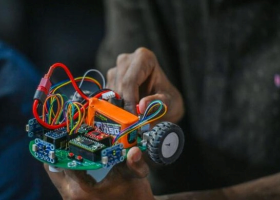
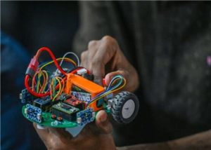
AI Enabled Real Time Maze Solving Robot
Project Overview:
This project presents an AI-enabled real-time autonomous maze-solving robot developed using a custom-designed PCB and embedded firmware.
The robot applies AI-based decision-making logic to interpret real-time sensor data, evaluate multiple movement possibilities, and select navigation paths on its own without human intervention.
By combining embedded intelligence, sensor fusion, and autonomous control, the system demonstrates a practical AIoT-based robotic platform suitable for competitions, learning, and experimentation.
Project Focus:
The primary focus of this project includes:
AI-driven real-time decision making
Autonomous path selection using sensor data
Compact and reliable custom PCB design
Robust motor and sensor interfacing under competition constraints
System Description:
The robot continuously collects distance data from sensors and processes it using an AI-inspired navigation algorithm running on the microcontroller.
Based on this data, the system analyzes possible paths, predicts safe movement directions, and autonomously decides whether to move forward, turn, or adjust speed at junctions.
This enables the robot to dynamically adapt its behavior as it explores the maze and progresses toward the goal.
Key Characteristics:
AI-enabled autonomous operation
Real-time sensor data processing
On-board decision making without external control
Optimized for structured maze environments
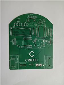
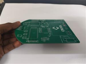
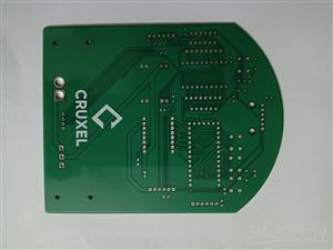
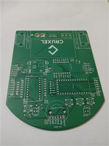
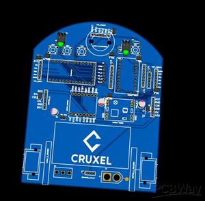
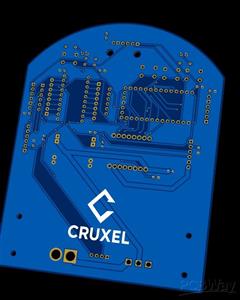
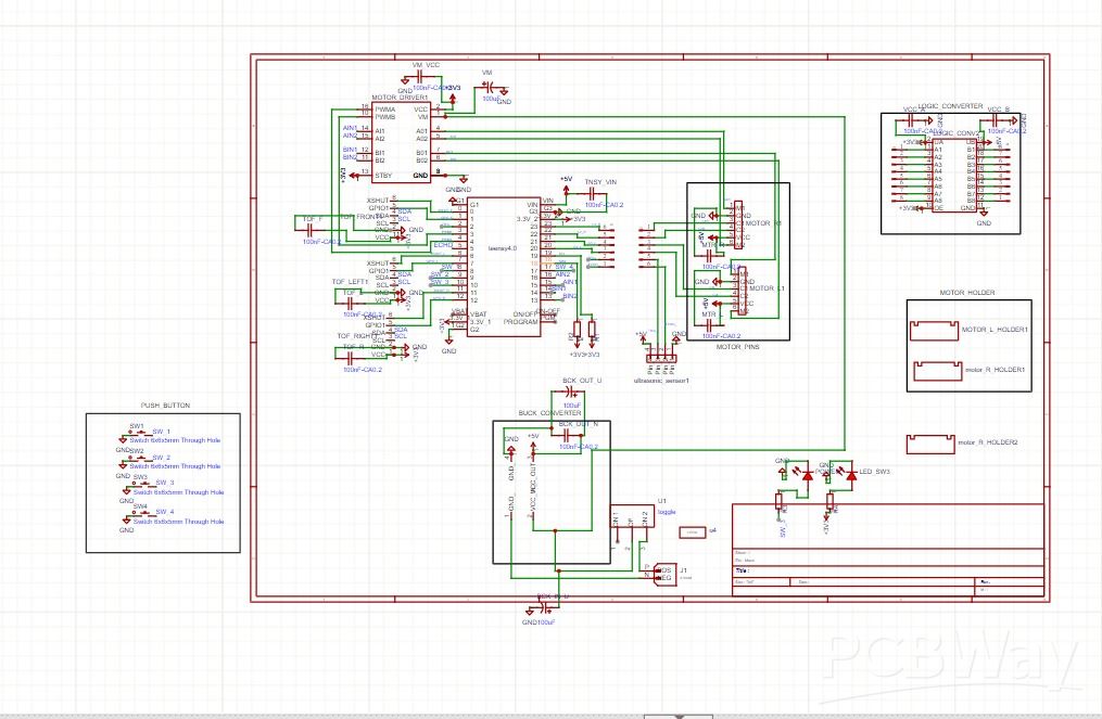
Hardware & PCB Design:
The robot is built on a custom PCB specifically designed for AI-enabled robotic applications.
The PCB integrates:
Microcontroller for real-time AI decision processing
Motor driver interface for precise motion control
Distance sensor connectors for environment perception
Buck converter for efficient power management
Push buttons for configuration and control
Status LEDs for debugging and system feedback
This compact hardware design improves reliability and reduces wiring complexity during competitive operation.
Software Architecture:
The firmware is structured to support AI-based autonomous behavior and rapid testing. Major software components include:
System initialization and pin configuration
Real-time sensor data acquisition
Motor control and PWM signal generation
PID-based motion stabilization
AI-based maze-solving and path decision logic
Main control loop for continuous operation
This modular structure enables fast tuning, debugging, and consistent performance.
AI Navigation & Control Logic:
The robot employs an AI-based rule and state-driven navigation algorithm that evaluates sensor inputs to make intelligent movement decisions.
Core AI features include:
Wall detection and distance evaluation
Path scoring and selection logic
PID-assisted motion correction
Intelligent decision making at maze junctions
Cell-based or wall-following maze-solving strategy
Through this approach, the robot learns the maze structure during traversal and determines the optimal path in real time.
Power System:
External battery supply
On-board buck converter for regulated logic voltage
Separate motor and logic power routing for noise reduction
/*******************************************************
 * AI Enabled Real-Time Maze Solving Robot
 * Uses sensor data, PID control, and AI-based
 * decision logic to autonomously find a path
 *******************************************************/

#include <Arduino.h>
#include <Wire.h>
#include <Encoder.h>
#include <VL53L1X.h>

// =====================================================
// AI DECISION ENGINE
// =====================================================
enum Action {
  MOVE_FORWARD,
  TURN_LEFT,
  TURN_RIGHT,
  TURN_BACK
};

Action decideNextMove(int frontDist, int leftDist, int rightDist) {
  int f = frontDist > 150;
  int l = leftDist  > 150;
  int r = rightDist > 150;

  if (f) return MOVE_FORWARD;
  if (l && !r) return TURN_LEFT;
  if (r && !l) return TURN_RIGHT;
  return TURN_BACK;
}


// -------------------- Pins --------------------
#define LED_PIN 10

// Motor Driver
#define AIN1 15
#define AIN2 16
#define BIN1 13
#define BIN2 14
#define PWMA 4
#define PWMB 3

// XSHUT Pins
#define XSHUT_FRONT 0
#define XSHUT_RIGHT 11
#define XSHUT_LEFT  6

// -------------------- Speed Config --------------------
#define FORWARD_SPEED 50
#define MAX_SPEED 60

// -------------------- Sensors --------------------
VL53L1X sensorFront;
VL53L1X sensorLeft;
VL53L1X sensorRight;

// -------------------- Encoders --------------------
Encoder leftEncoder(21, 20);
Encoder rightEncoder(23, 22);

// -------------------- Distance Readings --------------------
int df = 500, dl = 500, dr = 500;

// -------------------- PID --------------------
float Kp_wall = 0.5;
float Kd_wall = 2.0;

// -------------------- Conversion --------------------
long mmToTicks(int mm) { return mm * 10.13; }
long angleToTicks(int deg) { return deg * 11.048; }


// =====================================================
// MOTOR CONTROL
// =====================================================
void setMotor(int in1, int in2, int pwm, int speed) {
  digitalWrite(in1, speed > 0);
  digitalWrite(in2, speed < 0);
  analogWrite(pwm, abs(speed));
}

void stopMotors() {
  analogWrite(PWMA, 0);
  analogWrite(PWMB, 0);
}

void resetEncoders() {
  leftEncoder.write(0);
  rightEncoder.write(0);
}

// =====================================================
// FORWARD WITH PID
// =====================================================
void moveForwardPID(int mm) {
  resetEncoders();
  int prevError = 0;

  while (true) {
    df = sensorFront.read();
    dl = sensorLeft.read();
    dr = sensorRight.read();

    int error = dl - dr;
    int correction = Kp_wall * error + Kd_wall * (error - prevError);
    prevError = error;

    int lSpeed = constrain(FORWARD_SPEED + correction, 0, MAX_SPEED);
    int rSpeed = constrain(FORWARD_SPEED - correction, 0, MAX_SPEED);

    setMotor(AIN1, AIN2, PWMA, lSpeed);
    setMotor(BIN1, BIN2, PWMB, rSpeed);

    long traveled = (abs(leftEncoder.read()) + abs(rightEncoder.read())) / 2;
    if (traveled >= mmToTicks(mm)) break;
  }

  stopMotors();
}

// =====================================================
// ROTATION
// =====================================================
void rotate(int dir, int angle) {
  resetEncoders();
  long ticks = angleToTicks(angle);

  while (abs(leftEncoder.read()) < ticks) {
    setMotor(AIN1, AIN2, PWMA, dir * MAX_SPEED);
    setMotor(BIN1, BIN2, PWMB, -dir * MAX_SPEED);
  }

  stopMotors();
}

// =====================================================
// SETUP
// =====================================================
void setup() {
  Serial.begin(115200);

  pinMode(AIN1, OUTPUT); pinMode(AIN2, OUTPUT);
  pinMode(BIN1, OUTPUT); pinMode(BIN2, OUTPUT);
  pinMode(PWMA, OUTPUT); pinMode(PWMB, OUTPUT);
  pinMode(LED_PIN, OUTPUT);

  Wire.begin();
  Wire.setClock(400000);

  pinMode(XSHUT_FRONT, OUTPUT);
  pinMode(XSHUT_LEFT, OUTPUT);
  pinMode(XSHUT_RIGHT, OUTPUT);

  digitalWrite(XSHUT_FRONT, HIGH);
  digitalWrite(XSHUT_LEFT, HIGH);
  digitalWrite(XSHUT_RIGHT, HIGH);

  sensorFront.init(); sensorFront.setAddress(0x2A);
  sensorLeft.init();  sensorLeft.setAddress(0x2B);
  sensorRight.init(); sensorRight.setAddress(0x2C);

  sensorFront.startContinuous(20);
  sensorLeft.startContinuous(20);
  sensorRight.startContinuous(20);
}

// =====================================================
// MAIN LOOP
// =====================================================
void loop() {

  df = sensorFront.read();
  dl = sensorLeft.read();
  dr = sensorRight.read();

  Action action = decideNextMove(df, dl, dr);

  switch (action) {
    case MOVE_FORWARD:
      moveForwardPID(250);
      break;

    case TURN_LEFT:
      rotate(1, 90);
      break;

    case TURN_RIGHT:
      rotate(-1, 90);
      break;

    case TURN_BACK:
      rotate(1, 180);
      break;
  }

  delay(100);
}
AI Enabled Real Time Maze Solving Robot
Project images are for reference only. Actual production is based on the manufacturing files on the project page.
Please review the designer's notes (e.g., PCB thickness) and select the appropriate options.
PCBWay is not responsible
for issues caused by unsuitable parameter selections.
For more important ordering information, please refer to
Read More


Raspberry Pi 5 7 Inch Touch Screen IPS 1024x600 HD LCD HDMI-compatible Display for RPI 4B 3B+ OPI 5 AIDA64 PC Secondary Screen(Without Speaker)
BUY NOW


- Comments(0)
- Likes(38)
 More by Kailash s
-
Programmable Mist Maker - XIAO / QT PY Extension
1061 2 1 -
RadioHAT - Raspberry Pi radio development platform
867 0 2 -
-
-
-
-
ARPS-2 – Arduino-Compatible Robot Project Shield for Arduino UNO
3323 0 6 -
A Compact Charging Breakout Board For Waveshare ESP32-C3
3933 3 8 -
AI-driven LoRa & LLM-enabled Kiosk & Food Delivery System
4320 2 2


