


|
|
EasyEda |
Encoder Decoder PCBs
My project include two boards. One board is encoder board and another one is decoder board.
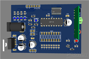
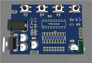
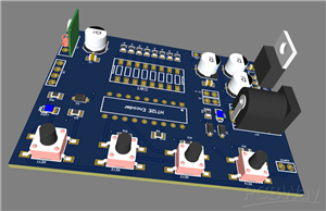
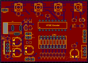
ENCODER
I will start with encoder board. The function of this board is to transmit the data wirelessly to decoder board. The main chip used in this board is HT12E encoder chip. To power the board, i have two options, one is the DC power jack with voltage regulator. Other one is the direct 5V pin-out. I have also added power LED there to indicate whether the board is powered or not. Now to set the address of chip, i have used DIP switch. After setting the address, we have to transmit the data. For that i have added four push-buttons. Setting them high or low. If we need to give the data externally, not using push-buttons, we can use digital dataIN pins. We can connect them with our Micro-controller to set them high or low. Make sure that if we are using the push-buttons, we have to attach the jumper on jumper pin header. Else if giving data externally, i need to remove the jumper. I have added the LED there(LED2). If it glows, it means it is manual mode. If not it means we are giving data externally. At last, there comes a transmitter to transmit the data. There is another pin named as dataOUT. if we do not have RF modules and we want to connect the encoder and decoder boards using wire, we can connect the dataOUT pin with dataIN pin on decoder board.
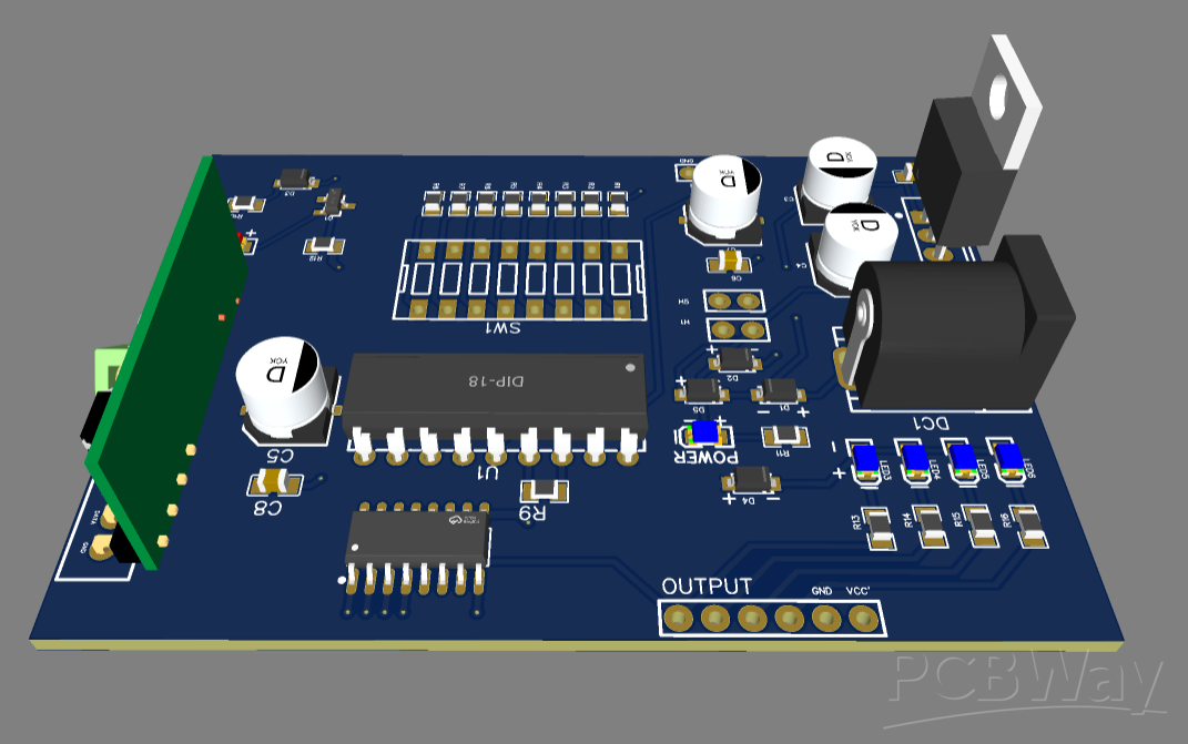
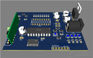
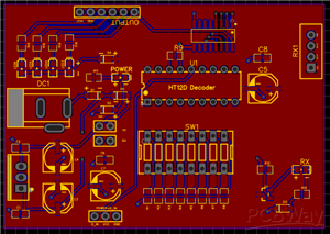
DECODER
Now there comes the decoder board. The function of this board is to receive the data wirelessly from encoder board. The main chip used in this board is HT12D decoder chip. To power the board, i have two options, one is the DC power jack with voltage regulator. Other one is the direct 5V pin-out. I have also added power LED there to indicate whether the board is powered or not. Now to set the address of chip, i have used DIP switch. Now it's time to receive data. First lets talk about the indicator circuit. I have created a simple LED circuit. when the receiver receives the data, this LED lights up. It confirms that out communication is working properly. I have added the circuits containing four LEDs. They indicate the data received. It means they tell us which pin is high and which is low on receiver side. I have used ULN2003 transistor array. This IC allows us to control the external circuit using decoder data being received. Using this IC, we can operate any voltage circuit using the 5V signals. To operate the motors, I have added a header pin VCC’ with which we can prevent the back EMF. I have added dataIN pin also. I can connect it with encoder board to receive data using wire.
Encoder Decoder PCBs
*PCBWay community is a sharing platform. We are not responsible for any design issues and parameter issues (board thickness, surface finish, etc.) you choose.


Raspberry Pi 5 7 Inch Touch Screen IPS 1024x600 HD LCD HDMI-compatible Display for RPI 4B 3B+ OPI 5 AIDA64 PC Secondary Screen(Without Speaker)
BUY NOW


- Comments(0)
- Likes(0)
 More by Engineer
-
Programmable Mist Maker - XIAO / QT PY Extension
447 0 0 -
RadioHAT - Raspberry Pi radio development platform
348 0 1 -
-
-
-
-
ARPS-2 – Arduino-Compatible Robot Project Shield for Arduino UNO
2896 0 6 -
A Compact Charging Breakout Board For Waveshare ESP32-C3
3397 3 8 -
AI-driven LoRa & LLM-enabled Kiosk & Food Delivery System
3723 2 2


